Table of Contents

Related Manuals for NXP Semiconductors LPCXpresso824-MAX Board


Summary of Contents for NXP Semiconductors LPCXpresso824-MAX Board
- Page 1 UM10830 User Manual for LPCXpresso824-MAX Board User Manual for Rev. 1.2 — 20 June 2019 LPCXpresso824-MAX Board Document information Info Content Keywords LPCXpresso824-MAX, OM13071, LPC824 Abstract LPCXpresso824-MAX User Manual...
- Page 2 LPCXpresso824-MAX NXP Semiconductors User Manual Revision history Date Description 20180209 First release 20190613 Document update Contact information For more information, please visit: http://www.nxp.com For sales office addresses, please send an email to: salesaddresses@nxp.com UM10830 All information provided in this document is subject to legal disclaimers.
-
Page 3: Introduction
The LPCXpresso family of boards provides a powerful and flexible development system for NXP's Cortex-M MCUs. They can be used with a range of development tools. The LPCXpresso824-MAX board is developed by NXP to enable evaluation of and prototyping with the LPC82x family of MCUs. -
Page 4: Board Layout
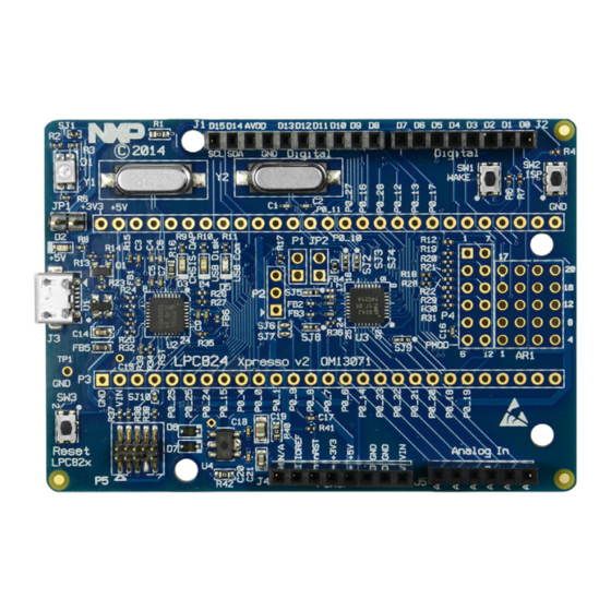
LPCXpresso824-MAX NXP Semiconductors User Manual 2. Board Layout Figure 2 and 3 below shows the layout of the LPCXpresso824-MAX board, indicating location of jumpers, buttons and connectors/expansion options. Fig 2. Board layout Fig 3. Default jumpers Table 1 below shows the layout of the LPCXpresso824-MAX board, indicating location of jumpers, buttons, connectors/expansion options and MCU devices. - Page 5 LPCXpresso824-MAX NXP Semiconductors User Manual Table 1. Default jumpers, button and expansion connectors Circuit reference Description Reference section On-chip debug probe disable. Insert a jumper on this header to disable 5.1.1 the on-board debug probe when using an external probe.
-
Page 6: Getting Started
LPCXpresso824-MAX NXP Semiconductors User Manual 3. Getting Started This section describes the operation of the factory programmed demo program, and how to set up your board for code development with MCUXpresso IDE and/or third party tools. 3.1 Installing drivers and updating firmware The virtual com (VCOM) port provided by the debug probe on the board requires drivers to be installed when using Windows host computers. -
Page 7: Running Example/Demos
MCUXpresso SDK is intended for developers who prefer a more abstracted interface. The LPCXpresso824-MAX board may also be used with the mbed development environment, but is currently limited to mbed 2.0. Please refer to the mbed developer site for more information https://os.mbed.com/platforms/LPCXpresso824-MAX/. - Page 8 10. Connect the LPCXpresso824-MAX board the host computer, click Debug in the Quickstart panel. The IDE will search for available debug probes. Select the debug probe that appears for your board, then click OK.
- Page 9 Quickstart panel. You will see the build processing in the Console window to the right of the Quickstart panel. 14. Connect the LPCXpresso824-MAX board the host computer. 15. Click Debug in the Quickstart panel. The IDE will search for available debug probes.
-
Page 10: Using Lpcxpresso824-Max With 3Rd Party Ides
An external debug probe that supports ARM’s SWD interface, such as a SEGGER J-Link, LPC Link2 or PE Micro probe, can be used with the LPCXpresso824-MAX board. The external probe must be connected to header P5. When an external debug probe is used, a jumper shunt on JP1 must be installed before powering up the board in order to prevent the on-board debug contending with the external debug probe. -
Page 11: Buttons
LPCXpresso824-MAX NXP Semiconductors User Manual When JP1 is closed (jumper fitted), the on-board debug probe is held in reset, and an external debug probe can be connected using the P5 connector. 5.1.2 JP2 and P1: Target power consumption The JP2 jumper is provided to enable by placing an ammeter in line with JP2 pins. By default, the solder jumper (SJ2) bypasses the JP2 jumper. -
Page 12: Expansion Connectors/Headers
• USB Comm (blue): illuminates when the mbed serial port device is active. 6. Expansion connectors/headers The LPCXpresso824-MAX board provides an Arduino shield to add additional peripherals, sensors or other circuitry, including off-the-shelf expansion boards; this section describes these options. For further details please refer to the board schematics. - Page 13 LPCXpresso824-MAX NXP Semiconductors User Manual Table 2. Arduino expansion connector pin mappings (J4) Arduino signal LPC824 +3.3V IOREF Reset RESET +3V3 +5V0 Table 3. Arduino expansion analog connector pin mappings (J5) Arduino signal LPC824 pin P0_6 P0_14 P0_23 P0_22 P0_21 P0_20 Table 4.
-
Page 14: Pmod™ Headers
LPCXpresso824-MAX NXP Semiconductors User Manual 6.2.1 Pmod™ headers Pmod support is available on the LPCXpresso824-MAX:. • Pins 1 – 6 (left side) will support Pmod™ Type 2 (SPI) or Type 1 (GPIO). • Pins 7 – 12 (right side) design to support I2C. Will Pmod™ Type 1 (GPIO) interface. -
Page 15: Legal Information
Suitability for use — NXP Semiconductors products are not designed, authorized or warranted to be suitable for use in life support, life-critical or safety-critical systems or equipment, nor in applications where failure or malfunction of an NXP Semiconductors product can reasonably be expected to result in personal injury, death or severe property or environmental damage. -
Page 16: Table Of Contents
LPCXpresso824-MAX NXP Semiconductors User Manual 9. Contents Introduction ......3 Board Layout ......4 Getting Started .
Need help?
Do you have a question about the LPCXpresso824-MAX Board and is the answer not in the manual?
Questions and answers