Table of Contents
Advertisement
Quick Links
Chipsmall Limited consists of a professional team with an average of over 10 year of expertise in the distribution
of electronic components. Based in Hongkong, we have already established firm and mutual-benefit business
relationships with customers from,Europe,America and south Asia,supplying obsolete and hard-to-find components
to meet their specific needs.
With the principle of "Quality Parts,Customers Priority,Honest Operation,and Considerate Service",our business
mainly focus on the distribution of electronic components. Line cards we deal with include
Microchip,ALPS,ROHM,Xilinx,Pulse,ON,Everlight and Freescale. Main products comprise
IC,Modules,Potentiometer,IC Socket,Relay,Connector.Our parts cover such applications as commercial,industrial,
and automotives areas.
We are looking forward to setting up business relationship with you and hope to provide you with the best service
and solution. Let us make a better world for our industry!
Contact us
Tel: +86-755-8981 8866 Fax: +86-755-8427 6832
Email & Skype: info@chipsmall.com Web: www.chipsmall.com
Address: A1208, Overseas Decoration Building, #122 Zhenhua RD., Futian, Shenzhen, China
Advertisement
Table of Contents

Subscribe to Our Youtube Channel
Related Manuals for NXP Semiconductors OM13330


Summary of Contents for NXP Semiconductors OM13330
- Page 1 Chipsmall Limited consists of a professional team with an average of over 10 year of expertise in the distribution of electronic components. Based in Hongkong, we have already established firm and mutual-benefit business relationships with customers from,Europe,America and south Asia,supplying obsolete and hard-to-find components to meet their specific needs.
- Page 2 Keywords Fm+ I2C-bus, PCA9955, RGB and white LEDs, 16-channel × 8-bit PWMs Abstract The OM13330 is an add-on to 9-pin connector of the NXP I2C demo board 2005-1 or Fm+ I C-bus development board. This daughter board makes it easy to test and design with the PCA9955, a 16-channel Fast-mode Plus (Fm+) 57 mA constant current and outputs allow up to 40 V for LED supply.
- Page 3 UM10572 NXP Semiconductors PCA9955 demonstration board OM13330 Revision history Date Description 20120607 user manual; initial release Contact information For more information, please visit: http://www.nxp.com For sales office addresses, please send an email to: salesaddresses@nxp.com UM10572 All information provided in this document is subject to legal disclaimers.
-
Page 4: Introduction
I2C demonstration board 2005-1 (OM6275) or WIN-I2CUSB board (from www.nxp.com/redirect/demoboard.com) 3.4 Power requirements The NXP demonstration board I2C 2005-1 and OM13330 hardware obtain power from the PC USB port. Take care to not exceed the USB port current capabilities. UM10572 All information provided in this document is subject to legal disclaimers. -
Page 5: Installation
4. Installation 4.1 I2C demo board 2005-1 and WIN-I2CUSB Lite software The OM13330 is a daughter card to the OM6275 I2C demo board 2005-1. You can download the WIN-I2CUSB Lite Software, the OM6275 user manual UM10206, and find ordering information at the NXP web site ics.nxp.com/support/boards/i2c20051/. -
Page 6: Om13330 Connection To Win-I2Cusb Hardware Adapter Board
The Win-I2CUSB board should be disconnected from your PC before connecting the OM13330 board on to it. The OM13330 board has a 14-pin male connector (J2) that connects to the 14-pin male connector (J1) on the Win-I2CUSB board as shown in Figure Connect the OM13330 board to the Win-I2CUSB board before connecting the USB cable. -
Page 7: Hardware Description
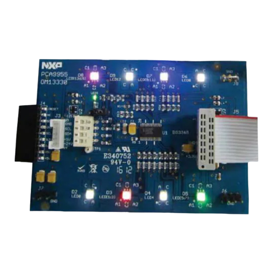
UM10572 NXP Semiconductors PCA9955 demonstration board OM13330 5. Hardware description Fig 3. PCA9955 demo board (OM13330) Figure 3 shows the following items on the hardware: • J4 (9-pin) is for connection to JP1 on I2C demo board 2005-1. • J3 and J5 (5-pin) are for connection to PCA9665/PCU9669 mini boards and cascade the second PCA9955 demo board. -
Page 8: Schematic
xxxx xxxxxxxxxxxxxxxxxxxxxxxxxxxxxx x xxxxxxxxxxxxxx xxxxxxxxxx xxx xxxxxx xxxxxxxxxxxxxxxxxxxxxxx xxxxxxxxxxxxxxxxxxxxxx xxxxx xxxxxx xx xxxxxxxxxxxxxxxxxxxxxxxxxxxxx xxxxxxxxxxxxxxxxxxxxxx xxxxxxxxxxx xxxxxxx xxxxxxxxxxxxxxxxxxx xxxxxxxxxxxxxxxx xxxxxxxxxxxxxx xxxxxx xx xxxxxxxxxxxxxxxxxxxxxxxxxxxxxxxx xxxxxxxxxxxxxxxxxxxxxxxx xxxxxxx xxxxxxxxxxxxxxxxxxxxxxxxxxxxxxxxxxxxxxxxxxxxxx xxxxxxxxxxx xxxxx x x 5-pin connector to/from PCU9669 UFm I2C master board to drive PCU9955 or +3.3 V +5 V to/from another I2C slave PCA/PCU9955... -
Page 9: Om13330 Demonstration Board Main
UM10572 NXP Semiconductors PCA9955 demonstration board OM13330 7. OM13330 demonstration board main components Table 1. OM13330 demo board main components Device Description Address/LED output Location PCA9955TW 16-channel Fm+ I2C-bus 57 mA 0xC0 for I2C demo board 2005-1 constant current LED driver... - Page 10 UM10572 NXP Semiconductors PCA9955 demonstration board OM13330 – ‘Other’ GRPPWM is group PWM for global brightness control, GRPFREQ is group frequency for global blinking control when group control = blinking in Mode 2 register, PWMALL is brightness control for all LED outputs, OFFSET is control LED...
- Page 11 UM10572 NXP Semiconductors PCA9955 demonstration board OM13330 Fig 6. Device configuration screen for PWM[0:7] Fig 7. Device configuration screen for PWM[8:15] UM10572 All information provided in this document is subject to legal disclaimers. © NXP B.V. 2012. All rights reserved.
- Page 12 UM10572 NXP Semiconductors PCA9955 demonstration board OM13330 Fig 8. Device configuration screen for LEDOUT Fig 9. Device configuration screen for LED output current setting UM10572 All information provided in this document is subject to legal disclaimers. © NXP B.V. 2012. All rights reserved.
- Page 13 UM10572 NXP Semiconductors PCA9955 demonstration board OM13330 Fig 10. Device configuration screen for ‘Other’ (Group and All registers) UM10572 All information provided in this document is subject to legal disclaimers. © NXP B.V. 2012. All rights reserved. User manual Rev. 1 — 7 June 2012...
-
Page 14: Color Mixing And Blinking Leds
UM10572 NXP Semiconductors PCA9955 demonstration board OM13330 8.2 Color mixing and blinking LEDs To set up a blinking demo, repeat step 1 through step 7 as in Section 8.1, then do the following: 1. In the Mode 2 (= 0x25) selection window (middle left), check the ‘Group control = dimming’... -
Page 15: Abbreviations
UM10572 NXP Semiconductors PCA9955 demonstration board OM13330 10. Abbreviations Table 2. Abbreviations Acronym Description ElectroStatic Discharge Graphical User Interface C-bus Inter-Integrated Circuit bus Integrated Circuit Light-Emitting Diode Personal Computer Pulse Width Modulator Random Access Memory Red/Green/Blue RGBA Red/Green/Blue/Amber SMBus System Management Bus Universal Serial Bus 11. -
Page 16: Legal Information
In no event shall NXP Semiconductors, its affiliates or their suppliers be liable Notwithstanding any damages that customer might incur for any reason to customer for any special, indirect, consequential, punitive or incidental whatsoever, NXP Semiconductors’... -
Page 17: Table Of Contents
UM10572 NXP Semiconductors PCA9955 demonstration board OM13330 13. Contents Introduction ......3 Features ....... 3 Getting started .
Need help?
Do you have a question about the OM13330 and is the answer not in the manual?
Questions and answers