
Related Manuals for WPI EVOM


Summary of Contents for WPI EVOM
- Page 1 EVOM & EVOMX Epithelial Voltohmmeters INSTRUCTION MANUAL Serial No._____________________ 021308 World Precision Instruments...
-
Page 3: Table Of Contents
3. Placement of the electrode in the sample cup ...............7 4. Measuring Resistance ......................9 5. Measuring Voltage ....................... 10 INSTRUMENT MAINTENANCE ......................10 Electrodes ............................ 10 EVOM Meter ..........................12 ACCESSORIES............................13 TROUBLESHOOTING ........................... 15 SPECIFICATIONS ........................... 19 APPENDIX A: SUMMARY OF OPERATING INSTRUCTIONS ............20 APPENDIX B: IMPORTANT APPLICATION NOTES................ -
Page 5: Introduction
EVOM and STX2 electrode (included with the instrument). The EVOM qualitatively measures cell monolayer health and quantitatively measures cell confluence. When combined with WPI’s EndOhm chamber, the EVOM can also be used to perform trans endothelial electrical resistance measurement. -
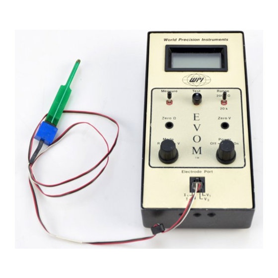
Page 6: Instrument Description
Required but not provided: small flat-head screwdriver to fit zero-adjustment screws. Meter • The EVOM / EVOMX meter is shipped with batteries installed. It is ready for use. Electrode • For resistance measurements only, the STX2 electrode can be used directly from dry storage without preconditioning. -
Page 7: Features And Controls
The toggle switch must be in the off position when this test is performed. (5) Measure R Pushbutton (EVOM): When the meter is in the R mode, pressing this button causes the resistance across the two electrode probes to be measured. The resistance measuring circuit will function only when this switch is depressed;... - Page 8 (5) Measure R Toggle Switch (EVOMX): In model EVOMX, the Measure R pushbutton has been replaced by a toggle switch and the alarm deactivated. The toggle switch must be in the off position (down) when performing the test above. In the up position, the switch is on for continuous resistance measurement.
-
Page 9: Instrument Self-Tests
Instrument Self-tests It is recommended that EVOM be put through the three self-tests described below before using it for the first time and then periodically thereafter. When there is a concern that the meter or the electrode is not functioning properly, the following three testing protocols may be used to confirm EVOM’s operating status. - Page 10 pressed, the meter should display zero or very close to zero. If not, adjust the “Zero Ω” screw with a small flat-head screwdriver until the meter shows a reading of 0. NOTE: Do not press either the Test R switch or the Measure R switch while adjusting the zero.
-
Page 11: Operating Instructions
(e.g., 0.1 – 0.15 M KCl) with the electrodes connected to the EVOM (power off) to allow the probes to equilibrate. With the voltage electrode connector pins thus short-circuited for several hours, the asymmetrical potential difference across the two voltage electrodes is reduced. - Page 12 it touches the bottom Fig. 1 of the dish each time, the reproducibility of the measurements is significantly improved. Even small differences in the apparent fluid resistance may occur if the depth to which the electrode tips are immersed varies. Place the electrode into the well so the tips just touch the bottom of the...
-
Page 13: Measuring Resistance
This value is independent of the area of the membrane used. NOTE: Resistance readings for 24 mm or larger diameter inserts obtained using the EVOM with the STX2 electrode should not be converted to unit area resistance. See additional discussion of this point in APPENDIX B “Special Note: 24 mm diameter (6-well) inserts and the STX electrodes”. -
Page 14: Measuring Voltage
Conversely, if the meter is reading negative, it means that the basal side is negative with respect to the apical side. See Appendix A for a summary of the operating instructions. INSTRUMENT MAINTENANCE Replacement Parts WPI Part # Description STX2 Replacement Electrode Set 2101... - Page 15 3. For resistance measurements, the electrode is now ready to use. 4. For voltage measurements, allow the electrode to equilibrate in the sterile electrolyte for 15 minutes. Then, adjust the “voltage zero” on the EVOM to balance any residual offset between the two probes.
-
Page 16: Evom Meter
Observe the polarity markings and replace battery cells accordingly. Reinsert the instrument into case and secure it. Check the R Zero and adjust, if necessary, with the EVOM in the R Mode. To conserve battery life, turn off the instrument when not in use. -
Page 17: Accessories
. The electrode incorporates a fixed pair of probes, 4 mm wide and 1 mm in thickness. Each probe has an outer (voltage) and an inner (current) electrode STX3 is an alternative electrode to the STX2 that can be used with both the EVOM and WORLD PRECISION INSTRUMENTS... - Page 18 STX100C and STX100F are optional electrodes specifically for use with the EVOMX, but may also be used with the EVOM. Specialized for high throughput screening (HTS) plates, they combine the advantages of the STX2 and Endohm, measuring TEER directly in the culture plate with good reproducibility.
-
Page 19: Troubleshooting
However, two qualitative methods may assist the user in determining that the electrode is working and will respond to an increase in resistance: 1. Use WPI’s CaliCell to test the electrode. CaliCell is a cell culture insert with a synthetic membrane that mimics a confluent epithelial membrane’s resistance in fluid. - Page 20 The electrode is dirty or not preconditioned. Clean the electrode as suggested above. Soak the electrode in electrolyte over night with cable connected to EVOM. Make sure the meter is turned off. After overnight soaking, adjust the Voltage zero to eliminate any residual offset voltage.
- Page 21 However, this drift is normal within 1% accuracy at 1000 ohm. If the error is more than 1% (>10Ω), then, the accuracy of your measurement will have a error that is larger than 1%. In that case, it is recommended that WPI recalibrate the instrument.
- Page 22 8. Resistance reading is higher than expected If the resistance readings (including the blank and cell culture) are much greater than expected, perform the Instrument Self-Test to confirm that the meter is functioning appropriately. If the problem persists, the likely cause is the electrode. Try cleaning the electrode (see the section on Cleaning the Electrode).
-
Page 23: Specifications
EVOM SPECIFICATIONS Membrane Voltage Range ±199.0 mV 0 to 1999 Ω & 0 to 20 KΩ Resistance Range AC Square Wave Current 2k Range: ±20 µA @ 12.5 Hz 20k Range: ±2 µA @ 12.5 Hz Power One 9-V alkaline battery, six 1.5-V alkaline AA cells. -
Page 24: Appendix A: Summary Of Operating Instructions
APPENDIX A: SUMMARY OF OPERATING INSTRUCTIONS For Voltage Measurements: For Resistance Measurements: • Connect the electrodes to the EVOM • Turn on EVOM • In the R mode, adjust the “Zero Ω” screw • Equilibrate the electrodes with the power with a small flat-head screwdriver until the meter shows a reading of 0. -
Page 25: Appendix B: Important Application Notes
IMPORTANT APPLICATION NOTES Resistance value of the “blank” insert When using an EVOM with an STX2 to measure a blank insert, the resistance value is typically between 120 to 180 Ω, depending on the specific brand of the insert. Many users mistakenly think this background resistance is due to the resistance of the blank filter. -
Page 26: Improving The Accuracy And Repeatability Of The System
1-2 Ω as compared to 5-10% of the total reading using the STX2 electrodes. The Endohm, together with the EVOM, offer the most accurate, convenient and economical solution for trans membrane electrical resistance measurement. -
Page 27: Appendix C: Resistance Calculations
NOTE: Resistance readings for 24 mm or larger diameter inserts obtained by using the EVOM with the STX2 electrode should not be converted to unit area resistance. The Endohm is recommended for these larger inserts. See additional discussion of this point in the section in APPENDIX B entitled “Special Note:... - Page 28 Resistance of a unit area = Resistance (Ω) x Effective Membrane Area* (cm * See manufacturing specifications for the particular insert Unit Area = 1 cm The unit area resistance is independent of the area of the membrane used and may be used to compare data obtained from inserts of different sizes.
-
Page 29: Warranty
WPI shall not be liable for any damage to data or property that may be caused directly or indirectly by use of this product. - Page 31 EVOM...
- Page 32 International Trade Center, 175 Sarasota Center Boulevard, Sarasota FL 34240-9258 Tel: 941-371-1003 • Fax: 941-377-5428 • E-mail: sales@wpiinc.com Astonbury Farm Business Centre • Aston, Stevenage, Hertfordshire SG2 7EG Tel: 01438-880025 • Fax: 01438-880026 • E-mail: wpiuk@wpi-europe.com Germany Liegnitzer Str. 15, D-10999 Berlin Tel: 030-6188845 •...
Need help?
Do you have a question about the EVOM and is the answer not in the manual?
Questions and answers