
Subscribe to Our Youtube Channel
Related Manuals for WPI SI-BF-100


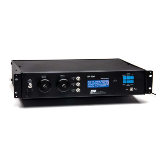
Summary of Contents for WPI SI-BF-100
- Page 1 SI-BF-100 Biofl uorometer for Fluorescence Imaging INSTRUCTION MANUAL Serial No._____________________ 061413 World Precision Instruments...
-
Page 2: Table Of Contents
SI-BF-100 CONTENTS ABOUT THIS MANUAL ........................1 INTRODUCTION ..........................1 Warnings ............................3 Parts List ............................3 Unpacking ............................3 INSTRUMENT DESCRIPTION ......................4 Front Panel ............................4 Back Panel ............................6 Setting Up the System ......................... 6 Changing the PMT Filters ......................7 Adding an LED Module ....................... - Page 3 World Precision Instruments...
-
Page 4: About This Manual
fi ring sequence of each LED can be programmed through controls on the front panel of the SI-BF-100. Additionally, you can set the intensity of the LED output, the sensitivity and fi lter frequency of the photomultiplier (PMT), the gain of the amplifi er, and the sampling average to optimize the emission signals that can be recorded. - Page 5 The Biofl uorometer can be used for many applications, limited only by your imagination. Some example applications are provided in the appendices: • Specifi c information on calcium measurement with several examples is located in. “Appendix A: Examples of Calcium Measurement” on page 19. •...
-
Page 6: Warnings
To avoid damage to the photomultiplier, it is imperative that the probe be attached to the optical input or that the input be capped when the SI-BF-100 is powered on. PHOTOMULTIPLIERS ARE EXPENSIVE TO REPLACE. -
Page 7: Instrument Description
INSTRUMENT DESCRIPTION The SI-BF-100 works with the SI-H muscle tester systems like the SI-MKB. Calcium Probe SI-BF-100 Biofluorometer SI-MKB Platform (sold separately) Fig. 2—The probe is mounted in a micromanipulator and positioned in the muscle tester cuvette in close proximity to the tissue sample. - Page 8 SI-BF-100 measurement) only require one photomultiplier. Others (like the ATPase measurement) require both photomultipliers. BNC Outputs: The analog outputs can be connected to a data acquisition system. They provide a normalized (relative) output based on the LED intensity and the PMT ( photomultiplier) gain factor.
-
Page 9: Back Panel
fi ring. It uses a 5.0V TTL pulse with high indicating that the LED is fi ring and low indicating that the LED is off. The unit can hold up to seven LED modules. Three modules are included with the SI-BF-100 that is confi gured for calcium measurement. -
Page 10: Changing The Pmt Filters
PHOTOMULTIPLIERS ARE EXPENSIVE TO REPLACE. Changing the PMT Filters Each photomultiplier has a fi lter on the front of the SI-BF-100 unit. The fi lter limits the emission light that gets sent to the photomultiplier to a single bandwidth of the spectrum. - Page 11 Fig. 9—The fi lters are located inside the fi lter holders. Use a Hex key to remove the two mounting screws that secure the fi lter holder to the face of the SI-BF-100 (Fig. 10). Fig. 10— (Left) Remove the two mounting screws.
-
Page 12: Adding An Led Module
You can add additional LED modules, if required. Turn off the power to the SI-BF-100 and unplug the instrument. Then, use a Phillips screw driver to remove the four screws on the top of the Biofl uorometer box. - Page 13 SI-BF100 Circuit Board PMT 2 PMT 1 LED 0 LED 2 LED 4 LED 6 LED 1 LED 3 LED 5 Remove Screws SI-BF100 Front Fig. 16— (Left) The circuit board inside the Biofl uorometer holds up to seven LED modules and has two photomultipliers.
-
Page 14: Changing The Sample Averages Of The Display
SI-BF-100 Changing the Sample Averages of the Display The sample average is shown on the display with the actual emissions ratio. The sample average (AVG SAMPLE) represents the number of samples that are averaged to arrive at the ratio measurement displayed. The system displays a running average of the measurements. -
Page 15: Confi Guring The System
Fig. 25—Dual display on the bottom line of the Parameter Display screen when the unit is operating in Dual Emission mode. Press the Display button to return to the main display. Confi guring the System Press the Setup button to enter the system confi guration menu. This menu toggles between the options that allow you to adjust the sampling frequency, gain adjust, photomultiplier gain voltage and fi... -
Page 16: Modifying The Photomultiplier Gain Voltage
SI-BF-100 Press the Setup button until the Gain Factor parameter displays. The current gain factor is shown on the display. Fig. 28—The gain adjust can be set from 1.00–4.10. Press the Up or Down button to change the gain adjust. -
Page 17: Setting Up Led Modules
Setting up LED Modules Each LED module can be individually confi gured. It can be enabled/disabled. You can set the output current, determine when (in a period) the LED illuminates and how much of the period that the LED remains lit. You can also see the combined output of the all enabled LEDs. -
Page 18: Operating Instructions
SI-BF-100 Calcium Measurement ATPase Measurement Module 0 On Modules 0, 1, and 2 On Dark Module 2 On Dark Module 1 On Sampling Frequency Sampling Frequency 1000Hz 1000Hz Fig. 32— Two example confi gurations are shown here. The default setup for a calcium (Fura-2) measurement unit has modules 0 and 1 (340nm) delay for 1% of the period and illuminate for 33%. -
Page 19: Ratio/Sample Averages Display
Fig. 36— The LED modules inside the Biofl uorometer are arranged as shown here. PMT Voltage–The photomultiplier voltage can be set between 0.5 and 1.0V. By default it is set to 0.7V. (See “Modifying the Photomultiplier Gain Voltage” on page 13.) Filter Cutoff–The output of the photomultiplier tends to be noisy, so it has a fi... -
Page 20: Confi Guration Parameters For Various Fluorophores
SI-BF-100 Confi guration Parameters for Various Fluorophores Fluorophores Parameters Fluo-4/Fura Red Indo-1 Fura-2 NADH/TAMRA Primary LED Wavelength Number of Primary LEDs Enabled Modules Primary LEDs Current of Primary LEDs 25ma 25ma 25ma 25ma %Delay of Primary LED % Width of Primary LEDs... -
Page 21: Accessories
M330l Micromanipulator Magnetic Base 94689 ATP Probe 94642 Calcium Probe 801513 Power Supply SW Ext 12V 45W for SI-BF-100 802232 12.5mm Optical Filter 632nm BP 802233 12.5mm Optical Filter 694nm BP 802234 12.5mm Optical Filter 510nm 84nm BP 802235 12.5mm Optical Filter 486nm BP 802236 12.5mm Optical Filter 405nm BP... -
Page 22: Appendix A: Examples Of Calcium Measurement
When the dye binds to calcium, the dye fl uoresces. Since the dye is no longer lipid-soluble, it is trapped inside the fi ber. Therefore, any fl uorescence, which is measured by the SI-BF-100, is indicative of the amount of calcium inside the fi bers. - Page 23 700nmFilter Wavelength [nm] Fig. 38— The excitation, emission and fi ltering of Fluo-4 and Fura Red using the SI-BF-100 Biofl uorometer. In Fig. 38, Fluo-4 is identifi ed in red and Fura Red is identifi ed in blue. The intrinsic absorbencies of the fl...
-
Page 24: Calcium Measurements With Indo-1
As indicated in Fig. 39, the 360nm LED excites Indo-1 when it is either bound or free of calcium. The emission fi lters are installed in the SI-BF-100 so that the emissions from calcium-bound Indo-1 are collected by PMT1, and the emissions from calcium- free Indo-1 are collected by PMT2. -
Page 25: Calcium Measurements With Fura-2
340nm Wavelength [nm] Fig. 40— Excitation, emission and fi ltering of Indo-1 with the SI-BF-100 Biofl uorometer. In Fig. 40, calcium-bound Fura-2 is identifi ed in red and calcium-free Fura-2 is identifi ed in blue. The intrinsic absorbance of Fura-2 is represented by dashed lines. -
Page 26: Appendix B: Example Of Atpase Activity Measurement
SI-BF-100 calcium concentrations. This is because less calcium is bound to the dye, and calcium-free dye is excited more effectively by longer wavelengths of light. The ratio between the fl uorescence intensities caused by 340nm and 380nm of light is an accurate indicator of the concentration of calcium in the fi... - Page 27 that have had their membranes removed or made permeable. The removal of membranes from the muscle fi bers permits the free movement of molecules between the cells and their incubation solutions. During the course of the experiment, the skinned muscle fi ber preparation is incubated in solutions that contain the enzymes and substrates needed for the reactions of the muscle contraction.
- Page 28 fi bers can be measured at the same time that ATPase activity is determined. In the WPI ATPase activity system, the skinned muscle fi ber preparation is incubated in a series of cuvettes containing solutions with the enzymes and substrates needed for the reactions of muscle contraction.
-
Page 29: Index
INDEX actin 19, 23 Module Confi g 14 action potential 19 modules 5 analog outputs 5 Module State 15 ATP 23, 24, 25 muscle tester 4 ATPase 1 myosin 19, 23 Avg Samples 16 NADH 2, 23, 24, 25 circuit board 10 neurotransmitters 19 confi... -
Page 30: Warranty
WPI shall not be liable for any damage to data or property that may be caused directly or indirectly by use of this product. - Page 31 International Trade Center, 175 Sarasota Center Blvd., Sarasota FL 34240-9258 Tel: 941-371-1003 • Fax: 941-377-5428 • E-mail: sales@wpiinc.com 1 Hunting Gate, Hitchin, Hertfordshire SG4 0TJ Tel: 44 (0)1462 424700 • Fax: 44 (0)1462 424701 • E-mail: wpiuk@wpi-europe.com Germany Zossener Str. 55, 10961 Berlin Tel: 030-6188845 •...
Need help?
Do you have a question about the SI-BF-100 and is the answer not in the manual?
Questions and answers