
Related Manuals for WPI EVOM EVA-MT-02-01


Summary of Contents for WPI EVOM EVA-MT-02-01
- Page 1 WORLD PRECISION INSTRUMENTS INSTALL GUIDE EVA-MT-02-01 EVOM™ Auto Automated TEER Measurement System Serial No._____________________ www.wpiinc.com 030923...
-
Page 3: Table Of Contents
EVA-MT-02-01 CONTENTS ABOUT THIS MANUAL ........................1 INTRODUCTION ..........................2 Features............................2 Notes and Warnings: ........................ 3 Parts List ............................3 Unpacking ........................... 3 INSTRUMENT DESCRIPTION ......................4 EVOM™ Auto System ........................ 4 Autosampler ..........................5 Interface Unit ..........................6 SYSTEM SETUP .......................... - Page 4 World Precision Instruments...
-
Page 5: About This Manual
EVA-MT-02-01 ABOUT THIS MANUAL The following symbols are used in this guide: This symbol indicates a CAUTION. Cautions warn against actions that can cause damage to equipment. Please read these carefully. This symbol indicates a WARNING. Warnings alert you to actions that can cause personal injury or pose a physical threat. -
Page 6: Introduction
INTRODUCTION The EVOM™ Auto automates TEER measurements. The instrument is controlled through a web browser, and the measurements are stored in the instrument and downloaded to your computer through the web browser. At present, the instrument supports MatTek, Corning, and Millipore 96 well plates. EVOM™ Auto is controlled wirelessly via Wi-Fi connectivity using an iPad (included with the system) or any other device with Wi-Fi connectivity. -
Page 7: Notes And Warnings
(1) Instruction Manual is available online at www.wpiinc.com/manuals. * The autosampler is adjusted for MatTek, Corning or Millipore plate by WPI, as requested by the end user. The system may be adjusted to use with other plate types in the Expert mode by users. (Refer to the Install Guide for instructions.) -
Page 8: Instrument Description
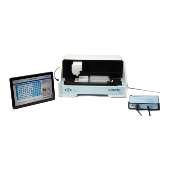
INSTRUMENT DESCRIPTION EVOM™ Auto System Fig. 2—The EVOM™ Auto System, includes the Control Tablet, the autosampler, the interface unit and the power supply (not shown). The EVOM™ Auto consists of these major components: • Autosampler – The robot contains the electrodes, a 3-compartment rinse stations, and a well plate. -
Page 9: Autosampler
EVA-MT-02-01 Autosampler Fig. 3—The autosampler takes the TEER measurements of the HTS well plate. Here are the primary components of the autosampler. Electrode Array Head – The electrode array rests in the Home position (shown in Fig. 3), just to the left of the rinse stations. The LED on the electrode array will: •... -
Page 10: Interface Unit
Looking at the autosampler measurement plate from the top, you can see the: • 4 Base Positioning Knobs used when you need to reposition the well plate when you are changing plate manufacturers • Rinse Station Pocket where the rinse station slides into place •... -
Page 11: System Setup
EVA-MT-02-01 SYSTEM SETUP The autosampler is packed with the lid taped in place. Remove all the components from the packing materials, and remove the protective tape. Setting up the System Remove the safety tape from the lid, and remove the lid from the autosampler. Connect the interface unit to the autosampler using the interface cable. - Page 12 Connect the power supply wall adapter to the wall outlet, and insert the barrel connector into the interface unit power supply port on the interface unit. Fig. 9—Connect the power cable to the interface unit. Install the provided Wi-Fi adapter into any one of the four USB ports on the side of the interface unit.
- Page 13 EVA-MT-02-01 Fig. 11—The autosampler ships with a red lock to prevent the electrode array connection port from moving during transit. Fig. 12—Remove the thumbscrew that secures the lock. Fig. 13—When the lock is removed, you have access to the electrode array connection port. World Precision Instruments...
-
Page 14: Installing The Electrode Array Head
Make sure that there are no well plates installed on the autosampler and make sure that the rinse station block is not installed on the autosampler plate. Electrode Array Connection Port Rinse Station Pocket Well Plate Area Fig. 14—This autosampler has no well plate and no rinse station installed. CAUTION: Never set anything (especially liquids) on top of the autosampler. - Page 15 EVA-MT-02-01 Remove the red electrode protection shield by releasing the Velcro strap. Fig. 16—Remove the protective sleeve. Make sure that the autosampler is in the home position on the left side of the unit. Locate the electrode array connection port on the back wall of the autosampler. Fig.
- Page 16 NOTE: The electrode array needs to be installed before trying to power up the unit, otherwise the software will not recognize the device and will not connect. Fig. 18—Hold the top of the autosampler with one hand, line up the electrode array with the connection port and press the electrode array into the connection port until it clicks.
-
Page 17: Starting The System
EVA-MT-02-01 Starting the System NOTE: Before you begin using the iPad, your IT department should register the device so that it is properly licensed to the organization. An iCloud account should be established to upload files. When you receive it, the iPad will be configured to begin using the autosampler, but it is recommended that you register it to your organization for optimal use of the device. - Page 18 Fig. 21—The blue ring illuminates around the power button, when the unit is powered on. Allow the system to boot up. On the iPad, navigate to the Setting area and select Wi-Fi. Select your EVOM system when it appears as an available network on the list of Wi-Fi networks.
- Page 19 EVA-MT-02-01 Fig. 23—Initialization screen. Fig. 24—Machine ready message displays briefly. Fig. 25—Main screen. World Precision Instruments...
-
Page 20: Installing The Rinse Stations
Installing the Rinse Stations Ensure that the electrode array is in the home position. Navigate to the Experiment window on the tablet and press the Go Home button. 2.` Slide the rinse station into the pocket on the left side of the measurement plate. Fig. -
Page 21: Installing The Well Plates
EVA-MT-02-01 Installing the Well Plates Ensure that the electrode array is in the home position. Your well plate needs to be positioned in between the alignment pins on the measurement plate with the notched corner and the A1 well in the back left corner. -
Page 22: Verifying Alignment
Verifying Alignment To ensure that the electrode array alignment was preserved during the shipping process, verify the alignment. Place the appropriate plate alignment tool (MatTek, Corning or Millipore) in the well plate location as described in “Installing the Well Plates” on page 17. Fig. - Page 23 EVA-MT-02-01 Select the Experiment menu to open the Experiment window, and press the Go Home button to send the electrode array to its home position. Fig. 33—The controls for the experiment are in the panel on the right side of the window. Remove the plate alignment tool and install the selected well plate.
-
Page 24: Appendix A: Using Expert Mode To Position Well Plate
APPENDIX A: USING EXPERT MODE TO POSITION WELL PLATE In Expert mode, you can adjust the positions of the first column in the X direction and the depth of measurement (Z direction). If the position of the electrodes needs to be adjusted, select the Expert Mode menu. -
Page 25: Well Plate Adjustments
EVA-MT-02-01 Fig. 36—The Expert window has two sections: well plate adjustments and rinse station adjustments. Well Plate Adjustments The well plate adjustments set the position parameters related to the measurements performed on the well plate. Travel Position Button – This button places the electrode array on column 1 above the well plate at the travel position. -
Page 26: Adjusting The Electrode Array Position
Fig. 37—The Left and Right buttons allow you to move the electrode array on the X-axis. Up and Down Buttons – These buttons move up or down in the Z direction. Use this adjustment to set the measuring height to make sure it does not puncture the membrane on the well plate. - Page 27 EVA-MT-02-01 Fig. 39—In the Rinse Station Adjustment area, press the Travel Position button to move the Array over rinse station 2. Press the Rinse Position button in the Rinse Station Adjustments area. This moves the electrode array to the rinsing position inside rinse station 2. Observe the depth and use the Down and Up buttons to lower or raise the electrode array, as needed.
- Page 28 Fig. 41—The electrode tips should be positioned above the plate, but should not touch it. Use the Up and Down buttons to change the measuring height as needed. Make sure that no electrodes are touching the alignment plate tool and that there is clearance for the electrodes.
- Page 29 EVA-MT-02-01 14. Visually verify that the electrodes are directly above the well plate openings. If necessary, use the Left and Right adjustment buttons to place the electrode array in the target area (X-axis adjustment). Fig. 43—Make sure the electrodes align with the holes in the well plate. 15.
- Page 30 Fig. 45—The electrodes are properly placed in the well plate. 17. Press the Go Home button. 18. When you are satisfied with the position, click the Save button. This saves the settings, and they become the new operational set of parameters. Or, press the Back button to cancel the action.
-
Page 31: Appendix B: Restore Factory Defaults
EVA-MT-02-01 APPENDIX B: RESTORE FACTORY DEFAULTS If you need to restore the factory default parameters, press the Restore icon the bottom of the Expert window. World Precision Instruments... -
Page 32: Appendix C: Adding Link To Ipad Home Screen
APPENDIX C: ADDING LINK TO IPAD HOME SCREEN By adding an EVOM™ Auto icon to the home screen of your iPad, you can open the program in full screen mode. To add a URL icon to the home screen, open Safari (or a web browser) and navigate to the URL (https://192.168.54.1:5000) on the tablet to load the EVOM™... - Page 33 EVA-MT-02-01 World Precision Instruments...
-
Page 34: Declaration Of Conformity
DECLARATION OF CONFORMITY World Precision Instruments... -
Page 35: Warranty
WPI shall not be liable for any damage to data or property that may be caused directly or indirectly by use of this product. - Page 36 175 Sarasota Center Blvd., Sarasota FL 34240-9258 Tel: 941-371-1003 • Fax: 941-377-5428 • E-mail: sales@wpiinc.com 1 Hunting Gate, Hitchin, Hertfordshire SG4 0TJ Tel: 44 (0)1462 424700 • Fax: 44 (0)1462 424701 • E-mail: wpiuk@wpi-europe.com Germany Pfingstweide 16, D-61169 Friedberg (Hessen), Germany Tel: +49 (0)6031 67708-0 •...
Need help?
Do you have a question about the EVOM EVA-MT-02-01 and is the answer not in the manual?
Questions and answers