gefran GTF-Xtra Installation And Connection
Power controller with overcurrent protection
Hide thumbs
Also See for GTF-Xtra:
- Configuration and programming manual (36 pages) ,
- Installation and operation manual (31 pages)
Advertisement
Quick Links
INSTALLATION AND CONNECTION
This section contains the instructions needed for correct installation of GTF controllers on the machine/host
system control panel and for correct connection of the power supply, inputs, outputs and interfaces.
CAREFULLY READ THE FOLLOWING WARNINGS BEFORE INSTALLING THE INSTRUMENT!
Disregard of such warnings could create electrical safety and electromagnetic compatibility problems, as well as
void the warranty.
ELECTRICAL POWER SUPPLY
• the controller DOES NOT have an On/Off switch: the user must install switch/isolator conforming to safety requisites
(CE mark) to cut off the power supply up-line of the controller.The switch must be installed in the immediate vicinity of the
controller in easy reach of the operator. A single switch can be used for multiple devices.
* the earth connection must be made with a specific lead
• if the product is used in applications with risk of harm to persons or damage to machines or materials, it MUST be
equipped with auxiliary alarm devices.
It is advisable to provide the ability to check for tripped alarms during regular operation.
NOTES ON ELECTRICAL SAFETY AND ELECTROMAGNETIC COMPATIBILITY
CE MARKING: EMC (electromagnetic compatibility) conformity in compliance with Directive 2014/30/EU and
following modifications.
Series GTF controllers are mainly intended for industrial use, installed on panels or control panels of production pro-
cess machines or systems. For purposes of electromagnetic compatibility, the most restrictive generic standards have
been adopted, as shown on the table.
LV (low voltage) conformity in compliance with Directive 2014/35/EU.
EMC conformity has been verified with the connections indicated on table 1 (see user's manual).
RECOMMENDATIONS FOR CORRECT INSTALLATION FOR PURPOSES OF EMC
Instrument power supply
• The power supply for the electronic instrumentation on the panels must always come directly from a cut-off device
with fuse for the instrument part.
• Electronic instrumentation and electromechanical power devices such as relays, contactors, solenoids, etc., MUST
ALWAYS be powered by separate lines.
• When the power supply line of electronic instruments is heavily disturbed by switching of thyristor power groups or by
motors, you should use an isolation transformer only for the controllers, grounding its sheathing.
• It is important for the system to be well-grounded:
- voltage between neutral and ground must not be > 1V
- Ohmic resistance must be < 6Ω;
• If the grid voltage is highly unstable, use a voltage stabilizer.
• In proximity of high-frequency generators or arc welders, use adequate grid filters.
• The power supply lines must be separate from instrument input and output lines.
• Supply from Class II or from limited energy source.
Input and output connections
Before connecting or disconnecting any connection, always check that the power and control cables are isolated from
voltage.
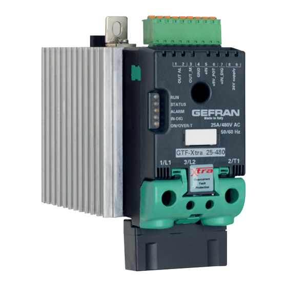
ELECTRICAL CONNECTIONS
Top view WITH OUT option Fieldbus
Top view OUT option Fieldbus
Key HB
Key HB
J3, J4
J2
RJ10 connectors
TTL port for PC configuration
RS485 serial line
Modbus
Input control signal (GND)
Input control signal (+)
Syncronous output for Master/
Potentiometer output power supply (+5Vdc)
Slave connection
Digital input (PWM input)
Alarm output
Power supply terminal 24Vac/Vdc
(solid state relay - HB option)
Key HB
J1
Power supply /control connector
Fixing screw at heatsink
Green Led (RUN)
Yellow Led (STATUS)
Identification label
Red Led (Alarm output HB)
Yellow Led (Status digital input)
Fixing screw at heatsink
Led: Green = Thyristor ON
Yellow = Temperature OVER
2/T1
1/L1
LOAD connection
LINE connection
3/L2
Reference connection of line voltage
PE EARTH
Appropriate devices must be provided: fuses or automatic switches to protect power lines.
• Connected outside circuits must be doubly isolated.
• it's necessary to:
- physically separate the input cables from those of the power supply, outputs, and power connections.
- use braided and shielded cables, with sheathing grounded at a single point.
Installation notes
Install the voltage stabilizer enclosed with the product (see Installation section).
- Moreover, the applications with solid-state units require a safety automatic switch to section the load power line.
To ensure maximum reliability, the device must be correctly installed in the panel in such a way as to obtain adequate heat
exchange between the heat sink and the surrounding air under conditions of natural convection.
Fit the device vertically (maximum angle 10° to the vertical axis)
• Vertical distance between a device and the panel wall >100mm
• Horizontal distance between a device and the panel wall at last 20mm
• Vertical distance between a device and the next one at last 300mm.
• Horizontal distance between a device and the next one at last 20mm.
Check that the cable holder runners do not reduce these distances, in this case fit the cantilever units opposite the panel
so that the air can flow vertically on the dissipator without any obstacles.
• Dissipation of device thermic power with effects on installation room temperature.
• Thermal power dissipation with limits on installation room temperature.
• Requires exchange with external air or an air conditioner to transfer dissipated power outside the panel
• maximum limits of voltage and derived power of transients on the line, for which the solid state power unit contains
protective devices (based on the model).
• presence of dispersion current in GTF in non-conducting state (current of a few mA due to RC Snubber circuit to
protect).
GEFRAN S.p.A. assumes no liability for any damage to persons or property deriving from tampering, from
incorrect or improper use, or from any use not conforming to the characteristics of the controller and to
the instructions in this User Manual.
Conformity: TC RU C-IT.
AЛ32.B.00422
GTF Standard
Address x 1
Address x 10
Switch for serial line
1.
Supply/control connnector
2.
HB key calibration
3.
TTL port for configuration
4.
LED indicators
5.
Power terminal "Line" (1/L1)
6.
Power terminal "Load" (2/T1)
Conformity
UL
CSA
C/UL/US File
Conformity C/CSA/US
no. E243386
CoFC no. 70002856
vol. 1 sez. 5
This device conforms to European Union Directive
2014/30/EU and 2014/35/EU with reference to
standard: EN 60947-4-3 (product)
GTF with RS485 option
7.
Heatsink
8.
Attachment DIN bar
9.
Switch serial line terminal
10.
RS485 serial port connector
11.
Address Rotary switch
12.
GTF-Xtra Surge protector
OVERCURRENT PROTECTION
INSTALLATION AND OPERATION MANUAL
Side 1
Installation and connection
Electrical connections
Side 2
Technical caracteristics
General caracteristics
Dimensions
Template/Installation
Derating curves
GEFRAN spa
via Sebina, 74 - 25050 Provaglio d'Iseo (BS)
Tel. 03098881 - fax 0309839063- Internet: http://www.gefran.com
RECOMMENDED WIRE GAUGES
GTF
CURRENT
TERMINAL
CABLE WIRE
WIRE TERMINAL
LEVEL
1/L1, 2/T1,
4 mm
2
Wire terminal / Eye
25A
PE
10 AWG
D. 6mm
1/L1, 2/T1,
10 mm
Wire terminal / Eye
2
40A
PE
7 AWG
D. 6mm
1/L1, 2/T1,
10 mm
Wire terminal / Eye
2
50A
PE
7 AWG
D. 6mm
1/L1, 2/T1,
16 mm
Wire terminal / Eye
2
60A
PE
5 AWG
D. 6mm
Wire stripped for
3/L2
0.25 ...2.5 mm
2
-
8 mm or with tag
(Ref. Vline)
23...14 AWG
terminal
Note: Cables must be copper "Stranded Wire" or "Compact-Stranded Wire" type with maximum operating
temperature 60/75°C
GTF-Xtra
POWER CONTROLLER WITH
code 80313C - 12/2020 - ENG
TIGHTENING TORQUE /
TOOL
2.5 Nm /
Phillips screwdriver
PH2 - PH3
2.5 Nm /
Phillips screwdriver
PH2 - PH3
2.5 Nm /
Phillips screwdriver
PH2 - PH3
2.5 Nm /
Phillips screwdriver
PH2 - PH3
0.5 ...0.6 Nm /
Flat-head screwdriver tip
0.6 x 3.5 mm
Advertisement

Subscribe to Our Youtube Channel
Related Manuals for gefran GTF-Xtra


Summary of Contents for gefran GTF-Xtra
- Page 1 • Electronic instrumentation and electromechanical power devices such as relays, contactors, solenoids, etc., MUST Electrical connections GEFRAN S.p.A. assumes no liability for any damage to persons or property deriving from tampering, from ALWAYS be powered by separate lines. incorrect or improper use, or from any use not conforming to the characteristics of the controller and to •...
- Page 2 (Table 2 EN60947-4-3) Indicates contents of sections, general instructions, notes, GTF 60 (with fan) AC 56a: single-phase transformers (not allowed , for application consult Gefran) GTF 50 (with fan and other points to which the reader’s attention needs to PA - Load management by adjusting the firing angle (only configuration single- be called.
Need help?
Do you have a question about the GTF-Xtra and is the answer not in the manual?
Questions and answers