KNX GIRA Manual
Hide thumbs
Also See for GIRA:
- Operating instructions manual (13 pages) ,
- Quick start manual (10 pages) ,
- Quick start manual (11 pages)
Advertisement
Quick Links
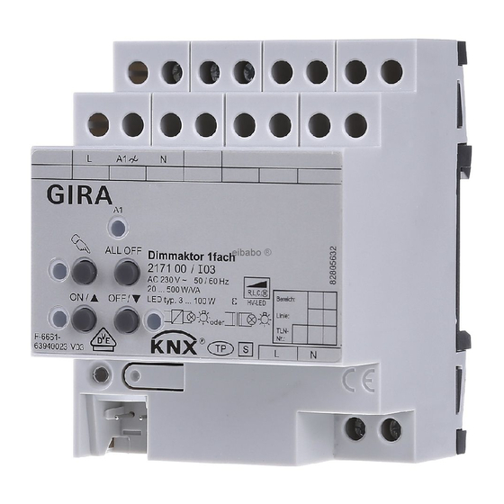
Dimming actuator
Dimming actuator, 1-gang
Order no.: 2171 00
Dimming actuator, 2-gang
Order no.: 2172 00
Dimming actuator, 4-gang
Order no.: 2174 00
Operating instructions
1
Safety instructions
Electrical devices may only be mounted and connected by electrically skilled persons.
Serious injuries, fire or property damage possible. Please read and follow manual fully.
Danger of electric shock. Always disconnect before carrying out work on the device or load.
Danger of electric shock. Device is not suitable for disconnection from supply voltage. The load
is not electrically isolated from the mains even when the output is switched off.
Risk of destruction of the dimmer and load if the set operating mode and load type do not
match. Set the correct dimming principle before connecting or exchanging the load.
Fire hazard. For operation with inductive transformers, each transformer must be fused on the
primary side in accordance with the manufacturer's instructions. Only safety transformers ac-
cording to EN 61558-2-6 may be used.
These instructions are an integral part of the product, and must remain with the end customer.
The connected load and dimmer quality on LED lamps are dependent on the type of lamp
and installation conditions. The connected load of the specified values could vary. We
cannot assume any guarantee for proper function, dimming results and dimming quality.
2
Device components
32575362
10867485
Figure 1: View of dimming actuator 2-gang
04.12.2019
1 / 16
Advertisement

Subscribe to Our Youtube Channel
Related Manuals for KNX GIRA


Summary of Contents for KNX GIRA
- Page 1 Dimming actuator Dimming actuator, 1-gang Order no.: 2171 00 Dimming actuator, 2-gang Order no.: 2172 00 Dimming actuator, 4-gang Order no.: 2174 00 Operating instructions Safety instructions Electrical devices may only be mounted and connected by electrically skilled persons. Serious injuries, fire or property damage possible. Please read and follow manual fully. Danger of electric shock.
- Page 2 Function System information This device is a product of the KNX system and complies with the KNX directives. Detailed tech- nical knowledge obtained in KNX training courses is a prerequisite to proper understanding. The function of this device depends upon the software. Detailed information on loadable soft- ware and attainable functionality as well as the software itself can be obtained from the manu- facturer´s product database.
-
Page 3: Operation
Dimming actuator Product characteristics – Automatic or manual selection of the dimming principle suitable for the load – Protected against no-load, short-circuit and overheating – Signal in the event of a short-circuit – Outputs can be operated manually – Feedback of the switching position and the dimming value –... - Page 4 Dimming actuator Status indication The status LED A1… (5) indicate the states of the outputs. – Off: Output switched off – On: Output switched on – Flashes slowly: Output in manual mode – Flashes quickly: Output disabled via continuous manual mode Operating modes –...
- Page 5 Dimming actuator ■ Operate the output with the button ON/n or the button OFF/o. Short: switch on/off. Long: dim brighter/darker. Release: Stop dimming. The LEDs ON/n and OFF/o indicate the status. Short-term manual operation: After running through all of the outputs the device exits manual mode after another brief press.
- Page 6 Dimming actuator Connecting lamp load Figure 4: Dimming actuator – Connection example Do not exceed permissible total load including transformer power dissipation. Operate inductive transformers with at least 85% nominal load. Mixed loads with inductive transformers: ohmic load max. 50%. HV-LED lamps and compact fluorescent lamps: Only connect lamps of one manufacturer and of the same type on the same output.
- Page 7 Dimming actuator Choose power boosters that are suitable for the dimmer and load. Program the operation with Universal power extensions in the device or – with devices up to version V01 – set the maximum brightness to 90 %. For more information please see instructions of the re- spective power pack.
- Page 8 Dimming actuator CAUTION! Danger of destruction. 400 V are shorted when outputs switched in parallel are con- nected to different outer phase conductors. The device will be destroyed. Always connect outputs switched in parallel to the same outer phase conductor. ■...
- Page 9 Dimming actuator Figure 7: Installing the cover ■ Route the bus line towards the rear. ■ Install cover on top of the bus terminal so that it snaps into place (Figure 7). Removing the cover Figure 8: Removing the cover ■ Press the cover to the side and pull it off (Figure 8). 5.2 Commissioning Loading the physical address and application software CAUTION!
- Page 10 Dimming actuator When deployed as a speed controller, the device must be adapted to the minimum speed of the connected motor. CAUTION! Connected motors must not stop. Risk of destruction for motor and controlling device. Set the minimum speed in such a way that the motor does not stop at a minimum setting.
- Page 11 Fitting width 72 mm / 4 module KNX medium TP256 Commissioning mode S-mode Rated voltage KNX DC 21 ... 32 V SELV Current consumption KNX 15 mA Connection mode KNX device connection terminal Dimming actuator, 2-gang, order no. 2172 00 Rated voltage AC 110 ...
- Page 12 Fitting width 72 mm / 4 module KNX medium TP256 Commissioning mode S-mode Rated voltage KNX DC 21 ... 32 V SELV Current consumption KNX 15 mA Connection mode KNX device connection terminal Dimming actuator, 4-gang, order no. 2174 00 Rated voltage AC 110 ...
-
Page 13: Troubleshooting
0.5 ... 2.5 mm² Fitting width 144 mm / 8 module KNX medium TP256 Commissioning mode S-mode Rated voltage KNX DC 21 ... 32 V SELV Current consumption KNX 15 mA Connection mode KNX device connection terminal 6.2 Troubleshooting Connected LED lamps or compact fluorescent lamps switch off in the lowest dimming position or flicker The set minimum brightness is too low. - Page 14 Dimming actuator Check manufacturer's instructions. Exchange lamps for another type. Cause 2: Dimming principle and lamps do not optimally match. For HV-LED: Check operation in another dimming principle, reduce connected load as well if necessary. For LV-LED: Check the lamp operating device and replace as necessary. With the "Universal"...
- Page 15 Dimming actuator Enable manual control. Output cannot be operated. Cause 1: Manual control has not been programmed. Reprogram device. Cause 2: Manual control via bus disabled. Enable manual control. None of the outputs can be operated. Cause 1: All of the outputs are disabled- Cancel disabling.
-
Page 16: Warranty
The warranty is provided in accordance with statutory requirements via the specialist trade. Please submit or send faulty devices postage paid together with an error description to your re- sponsible salesperson (specialist trade/installation company/electrical specialist trade). They will forward the devices to the Gira Service Center. Gira Giersiepen GmbH & Co. KG...
Need help?
Do you have a question about the GIRA and is the answer not in the manual?
Questions and answers