
Subscribe to Our Youtube Channel
Related Manuals for KNX SATION-DM0101.0210


Summary of Contents for KNX SATION-DM0101.0210
- Page 1 Technical Manual SATION Dimming Actuator 1-fold SATION-DM0101.0210 WWW.SATION.COM.CN...
-
Page 2: Table Of Contents
Overview............................. 1 Diagram Drawing......................1 Usage...........................2 Structure Specification....................2 Manual operation and protection operation............. 2 Function........................3 Overview of the dimming channel function............3 Universal Interface Channel Function Overview..........4 Communication Object....................... 4 Object Corresponding Channel...................4 Channel Object......................5 Dimming Channel Object................... 6 Online State Object.....................6 The Object of the Universal Interface Channel..........7 Logic Object......................7 ETS Parameter.......................... - Page 3 3.4.10.2 Behavior After Power off/after Reset............27 Input Channel Configuration................28 3.4.11.1 The Input Channel is Configured With the Same Parameters....28 Composite Pattern Parameter Configuration............29 3.4.12.1 Dimming Control..................29 3.4.12.2 Shutter Control..................31 3.4.12.3 Switch Control..................31 Independent Pattern Parameter Configuration..........32 3.4.13.1 Switch......................
- Page 4 6. This product is NOT a toy, please make sure it is out of children touch. 7. Only be suitable for EIB/KNX system bus. 8. Others: The below sign indicates this product can’t be dealt as ordinary family rubbish, in order to avoid the possible environment and human health harm caused by the electrical waste, this product must follow recovery processing.
-
Page 5: Overview
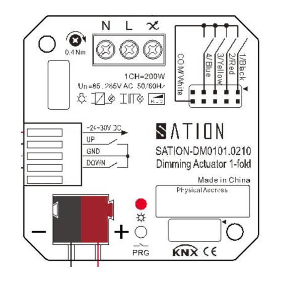
1 Overview This Use Manual refers to: ●SATION-DM0101.0210, Sation-Concealed 1 fold Dimming Actuator(200W) Diagram Drawing WWW.SATION.COM.CN... -
Page 6: Usage
Refer to figure 1. Diagram Drawing, the concealed 1-fold dimmer actuator contains a programming key, a programming indicator light, a KNX bus input, a 5 pin input terminal and a 3 pin output terminal. Five needle inputs contain two auxiliary power supply 24 v ~ 30 VDC input, two key hand input interface (UP and DOWN) and a common ground (GND), 3 needle output terminals contain zero line interface, firewire, and a light output interface. -
Page 7: Function
Function The channel has the associated parameter options that can be configured flexibly as needed. Overview of the dimming channel function Dimming Load type omic/acpacitive load / electronic transf.(trailing edge) Function: inductive loads / conventional transf.(leading edge) ESL/.LED without transformer(leading edge) ... -
Page 8: Universal Interface Channel Function Overview
Universal Interface Channel Function Overview Eliminate the jitter time 10-120ms, optional Long press the button 0.1-30s, optional Enter internal pull enable/disable Double key dimming function Dimming Double key curtain function On/Off Double key switch function On/Off Single key switch function Switch function Toggle function State function... -
Page 9: Channel Object
A dimmer actuator contains three global objects and objects corresponding to each channel. When a channel is activated, parameter configuration can be performed, and some objects are based on parameters. The configuration is shown in the object window. Each channel occupies 15 object positions. Therefore, the code range of channel A is 0-14. -
Page 10: Dimming Channel Object
Dimming Channel Object The following table is the corresponding object for a channel: Function Length Data Point Reading/Writing Type Switch Switch function 1 bit DPT 1.001 Writing Stair case light Delay turn off 1 bit DPT 1.001 Writing function Dim relatively Relative dimming 4 bit DPT 3.007... -
Page 11: The Object Of The Universal Interface Channel
The Object of the Universal Interface Channel Each channel has its corresponding five object numbers, which in turn are channel A:80-84;Channel B: 85-89;Channel C: 90-94;Channel D: 95-99. The object location will be permanently occupied and will not change due to schema changes. The following table is the corresponding object for a channel: Function Data Point Type... -
Page 12: Ets Parameter
The following table is the corresponding object for a logic function: Function Data Point Type Reading/Writing Logic input 1A Logic1 input A DPT 1.001 Writing Logic input 1B Logic 1 input B DPT 1.001 Writing Logic output 1 Logic 1 output DPT 1.001 Reading Logic output 1 Scene... -
Page 13: General Setting
General Setting Parameter Description: Parameter Name Range Remark [Default] Startup timeout 1‐60s Start the timeout parameter , after the device waits for the set [1s] time of the parameter, the application function is valid. Send“In operation” The "In operation" object is sent to the bus reporting device to ... -
Page 14: Function
Function Description Parameter Name Range Remark [默认值] Channel A inactive Inactive indicates that the channel active is disabled, and the active represents the enabled channel, when the channel parameters can be configured. If a channel is not used, choose inactive. When the active is selected, the parameters associated with the channel will appear for configuration, and some of the parameters will be selected. -
Page 15: Dim Relatively
Dim Relatively Relative dimming is performed continuous dimming operation on the basis of the current brightness. The step length is 100%, which means the dimming operation is from 0% to 100% or 100% to 0%. The dimming process can be stopped at any time. The dimming speed can be set. Name Length Dim relatively... -
Page 16: Time Functions
Name Option Remark [Default] Load type omic/capacitive load(trailing edge) omic/capacitive load(trailing edge) inductive loads/conventional transf.(leading edge) inductive loads (leading edge) ESL/LED without transformer(leading edge) ESL/LED without ESL/LED/Halogen with electronic transf.(trailing transformer(leading edge) edge) ESL/LED/Halogen with electronic ... -
Page 17: Staircase Light
15min, 20min, 30min, 45min, 60min The parameter On delay acts on the open operation, and Off delay acts on the closing operation. The following diagram shows the delay: 3.4.2.2 Staircase Light The corridor lighting mode can be configured to close the channel automatically when the delay time is used. - Page 18 名称 选项 备注 [默认] Duration staircase 0-30000s The channel opens for a duration and then closes automatically. [90s] Prewarning active Activate the warning function. If the function is not opened, the not active channel will not give warning instructions before closing. ...
-
Page 19: Absolute Values
Stair case light 1 bit Used for building function command reception. The channel function does not respond to Dim relatively and Dim absolute commands. Therefore, the channel does not automatically close after processing the light command received by these two objects, but it needs to receive external commands to close. - Page 20 Name Option Remark [Default] On-value setting Sub-function: value of start up This parameter sets the brightness 1-100% value when the channel receives the [100%] Switch object's open command. Last light value(Memory) This parameter indicates that the channel receives the last brightness value of the Switch object before the last channel is closed.
-
Page 21: Dimming Area
Dimming Area Set the dimming area by parameter "minimum light" and "maximum light". This brightness will vary only within the specified range. Name Option Remark [Default] Minimum light 1-100% Minimum allowable brightness [1%] value. Maximum light 1-100% Maximum allowable brightness [100%] value. -
Page 22: Specific Dimming Settings
brightness is 25%, then through open switch object receives a command when the channel is brightness will not 100%, but 85%, because of the limitation of maximum brightness by parameters. When the brightness is reduced by relative dimming or absolute dimming, the minimum brightness will be 25%, not 1%, or any other value. -
Page 23: Alarm Functions
Naame Range Remark [Default] Send dimming value after change(min. 2%) not active When the dimming value active changes at least 2%, the actual dimming value is sent. A state object that reflects the value of the dimming value will appear after the activation of the send dimming function, and the actual value of the dimmer will be sent when the condition is satisfied (at least 2%).The dimming object size is 1 byte. -
Page 24: Electric Load Alarm
When the overtemperature alarm function is activated, a new communication object is used to indicate the alarm status, and the communication object is 1 bit. Name Length Over temperature alarm 1 bit When alarm, send a value of 1. In order to avoid because of the high temperature lead to equipment damage, each channel is equipped with temperature detection, when the temperature more than internal threshold, the corresponding channel will generate alarm, and channel brightness will be reduced to 50%, after 30 seconds, if the temperature is still too high, the channel will be shut down. -
Page 25: Scene Function
activated the total control function is controlled by the total control object. Name Range Remark [Default] Central objects not active When you select active, the channel active responds to the total control object command. There are two total control objects: Switch (Switch object), Dim absolutely (absolute dimming object).The switch object can control the opening and closing of the channel that activates the total control function. -
Page 26: Submenu Scene
command is received through the scene object. Previously configured values, this allows you to modify the scene function of the channel flexibly. Name Length Scene 1 bit Scene call object Scenario number to call is through the scene, the scene for the range of 1-64, but the corresponding value of 0-63 to the actual scene, that is, when the number set the scene for 1, send the value of the actual object is zero, the scene number to 64, the value of the object is actually 63.This transformation is automatically converted by the device's internal program, which is only... - Page 27 Name Range Remark [Default] Save scene disabled Activate the learning enabled function. If the function is not activated, the learning command received will be ignored. Scene Nr.A-[H] 1-64,inactive The scenario number is [inactive] used to determine which of the eight scenarios is invoked.
-
Page 28: Automatic Function
0x03 0x83 0x04 0x84 0x05 0x85 0x06 0x86 0x07 0x87 0x08 0x88 0x09 0x89 0x0A 0x8A 0x0B 0x8B 0x0C 0x8C 0x0D 0x8D 0x0E 0x8E 0x0F 0x8F 0x10 0x90 0x11 0x91 0x12 0x92 0x13 0x93 0x14 0x94 0x15 0x95 0x16 0x96 0x17 0x97 0x18... -
Page 29: Additional Functions
Automatic 1 1 bit Invoke the automatic function object 1. Automatic 2 1 bit Invoke the automatic function object 2. Automatic 3 1 bit Invoke the automatic function object 3. Automatic 4 1 bit Invoke the automatic function object 4. The following figure is a screenshot of automatic object configuration: object 1 has a light value of 40%, object 2 is 50%, object 3 is closed, and object 4 is 100%. -
Page 30: Blocking Objects
3.4.10.1 Blocking Objects Name Range Remark [Default] Behavior at Block 1 = value Off,nochange,Lightvalue(10%,20%,30%,40%, Defines the dimming behavior 50%,60%,70%,80%,90%,100%) when the object is blocked. [no change] Behavior at Block 1 = value Off,nochange,Lightvalue(10%,20%,30%,40%, Defines the dimming behavior 50%,60%,70%,80%,90%,100%) when the object is returned to [no change] normal. -
Page 31: Behavior After Power Off/After Reset
be done, such as setting a luminance value, or closing the channel, and so on. Blocking object 1 has precedence over blocking object 2.When blocking object 2 received blocking command, channel perform blocking object 2 corresponding operation, then, blocking object 1 also received orders, then the channel will execute the object 1 corresponding operation, if the blocking object 2 received 0 (restoration) command, the command will not be performed because, blocking object 1 is still blocked, only when the blocking object 1, after receipt of the zero value (restoration) command object 2 operation. -
Page 32: Input Channel Configuration
Input Channel Configuration Parameter Name Range Remark [Default] Function Input Type A / B 、C / D Channels unique Channel working mode: Channels grouped Channels unique means that Channels work in independent mode; Channels are represented as channel work in combination mode;... -
Page 33: Composite Pattern Parameter Configuration
Blocking object 1bit When the value 1 is received, the blocking channel (the channel will no longer generate any action), the value 0 returns to normal. Composite Pattern Parameter Configuration Parameter Name Range Remark [Default] Input A/B Dimming Work mode selection: dimming, ... - Page 34 Name Length Dimming on/off 1 bit Switch function, short button is valid Dimming 4 byte Dimming function, long key is effective When a group of channel configured to the dimming function, there will be two objects, a corresponding short key, one object used to control and off, a long four object corresponding to the key, is used to control the dimming.
-
Page 35: Shutter Control
3.4.12.2 Shutter Control Two key curtain control. Can control curtain, shutter. The following figure shows the parameters: Name Length Shutter Down/Up 1 bit Drive the curtain up and down, long button effective Stop/Blinds Open/Close 1 bit Stop moving, the short button is valid When curtain of channel A/B is configured to control, and parameter selection Up/Down, the long press A button, the device will send A signal, the curtain will move Up, long press B button, the device will send A 1 signal, the curtain will move Down. -
Page 36: Independent Pattern Parameter Configuration
When the channel A/B is configured as A combination switch mode, and the parameter On/Off is selected, press A to send 1 signal, and press B to send 0 signal. Independent Pattern Parameter Configuration There are 7 options for channel work: ●Switch ●Switch short/long ●One button dimming... -
Page 37: Switch Falling Edge/Rising Edge/Both Edge
3.4.13.1.1 Switch Falling Edge/Rising Edge/Both Edge Edge Configuration Parameter Table: Parameter Name Range Remark [Default] Value for rising/falling edge Open/close can be pressed/released at will When the channel chooses the edge Switch rising edge or the Switch falling edge, a On or Off signal will be sent under the corresponding action. -
Page 38: Toggle Rising/Falling Edge
Name Length Switch 1 bit Press the button to send corresponding signal, long press/short press are no influence 3.4.13.1.2 Toggle Rising/Falling Edge Rising channel can be configured to delay (press), or fall (release) toggle output. Each toggle based on State feedback last time, that means will toggle the object (Value for toggle) (State) associated with the target State object to work properly. -
Page 39: Send Status
Name Length Switch 1 bit Press the button to send corresponding signal, long press/short press are no influence. Value for toggle 1 bit The connection status object, which reflects the current state of the target, is used to toggle the function. Object Value for toggle to flip the normal implementation of function, therefore, must connect it to the target channel on the state of the object, if there is no target object, you should connect the Switch to the channel object. - Page 40 Parameter Range Remark [Default] Value for rising edge Send the signal when pressed. Value for falling edge Send the signal when released. Send cycle Periodically send signals Time interval for send cyclic 1-3000s Interval time Behavior at bus power up Send nothing Whether the bus is sent or not when...
-
Page 41: Send Value Rising/Falling/Both Edges
3.4.13.1.4 Send Value Rising/Falling/Both Edges There are two values that can be sent, one byte, one two, depending on your choice. WWW.SATION.COM.CN... - Page 42 The following table is 1 byte value parameter: Parameter Range Remark [Default] Value for rising/falling edge 0-255 Sends a 1 byte value on the set edge (up, down) For a 1 byte object, it can send any value within a range of 0-255 depending on your Settings. The following is the object description: Name Length...
-
Page 43: Send Value With On/Off Delay
Two value objects: Name Length Send forced setting 2 位 Send setting value. 3.4.13.1.5 Send Value With On/Off Delay The following table shows the delay sending parameters: Parameter Name Range Remark [Default] Delay time 0-60min Send value after delay setting [1s] time To Send sub- function value with on/off delay, is Send on or off value, delay some time before we... - Page 44 Parameter: Object Description: Name Length Switch 1 bit Press the delay to send the On value, and release the delay to send Off the value. WWW.SATION.COM.CN...
-
Page 45: Scene
3.4.13.2 Scene Scene function can be used to control one or more actuators of multiple channels, in order to realize the state of a scene. In addition, in the case of active learning function, can be sent through long key learning command. Parameter Description: Parameter Range... -
Page 46: Counter
Hex. Dez. Hex. Dez. 0x00 0x80 0x01 0x81 0x02 0x82 0x03 0x83 0x04 0x84 0x05 0x85 0x06 0x86 0x07 0x87 0x08 0x88 0x09 0x89 0x0A 0x8A 0x0B 0x8B 0x0C 0x8C 0x0D 0x8D 0x0E 0x8E 0x0F 0x8F 0x10 0x90 0x11 0x91 0x12 0x92 0x13... - Page 47 Parameter Description: Parameter Name Range Remark [Default] Sub-function Count rising In setting the edge count, count down up and Count falling down by default Count rising and falling Sending difference 0-65535 The current value is sent for each increment of the set value.
-
Page 48: Switch Short/Long
3.4.13.4 Switch short/long Long press/short can be independently assigned to open/close/flip/send values and other functions. WWW.SATION.COM.CN... - Page 49 Parameter Name Range Remark [Default] Value for keystroke short object 1 Working on short key Toggle Send value Nothing Value for keystroke long object 2 Working on long key Toggle Send value ...
- Page 50 The following figure is used for long press/short press, long press open, short press off: The following table shows the parameter description for selecting function Send value: WWW.SATION.COM.CN...
-
Page 51: One Button Dimming
Parameter Name Range Remark [Default] Value for keystroke short/long Send value The sub-function is selected as the send value. Send value 1 Byte-Value[0…255] Value selection: one byte unsigned Scene number value, one for the scenario value. 1 Byte-Value[0…255] 0-255 A byte unsigned value, ranging from 0 to 255. -
Page 52: One Button Shutter
same, every button to flip. Long keys to realize relatively light, reaches the maximum/minimum brightness change, no longer release button to stop the dimming. Because it is a single bond dimmer, so every time long keys that move light change direction. Assuming that the current dimmer upwards, the direction of the next move light downward. -
Page 53: Led Output
Object Description: Name Length Shutter 1 bit The curtain moves, the long button is valid. Blinds/Stop 1 bit The curtain stops, the short button is valid Value for change of direction 1 bit Indicating current direction. The long button controls the curtain movement, changing direction each time, and assuming that the current is moving upward, the next time it moves down. -
Page 54: Logic
forbidden for large current LED drivers. The LED can normally respond to the object value (1= open,0= close), or reverse display (0= open,1= close). Also, the LED lighting mode can be configured, which is always bright/flashing. Logic The device extension input contains two logical control blocks. Various input/output methods can be configured. - Page 55 default value is 0. Function Selection: Setting per logic Dynamic range Remark [default value] [default value] Disabled Switch The logical object can be configured as And/Or Scene operation, And the optional function has three kinds of ...
-
Page 56: Logic Object Type Switch
3.4.15.1 Logic Object Type Switch Parameter Name Range Remark [Default] Send condition Not automatic Set output condition Change of input Change of output Output inverted Set the output in reverse For sending condition change of input, when any activation state is changed, it is output state. For sending condition change of input, only after all the input signal is set logical operation, and the state is not the same as before, the state is output. -
Page 57: Logic Object Type Scene
In the figure above, only when three inputs are 1, And the result of the operation is 1, the output of the reverse is 0, And the other time output is 1. 3.4.15.2 Logic Object Type Scene Logical block configured to function after the scene, when logical operation result is 1, will output scene value, and only when every time logic operation results from 0 to 1, will output a scene. -
Page 58: Logic Object Type Byte Value
[Default] Scene number 1-64 Scene No setting. 3.4.15.3 Logic Object Type Byte Value Parameter Name Range Remark [Default] Byte value[0…255] 0-255 Sending byte. As with the scenario function, output a set byte value as long as the result of the logical operation is 1.
Need help?
Do you have a question about the SATION-DM0101.0210 and is the answer not in the manual?
Questions and answers