
Related Manuals for Hydac CSI-Connect


Summary of Contents for Hydac CSI-Connect
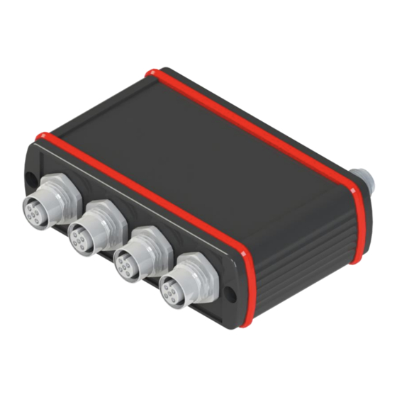
- Page 1 CSI-Connect Sensor-To-Cloud Device for seamless cloud integration of industrial sensors. Operating Instructions...
- Page 2 General CSI-Connect In this chapter, you will find helpful notes on handling these instructions. Manufacturer / publisher and responsible for the content: Address of the manufacturer Contact address HYDAC A/S HYDAC A/S Havretoften 5 Havretoften 5 5500 Langeskov 5500 Langeskov...
- Page 3 General CSI-Connect This manual was created for the following target group. Target group Tasks Owner This manual and the associated documents must be kept accessible at the installation location and for later use. Ask the employees to read and follow the manual and the associated documents, in particular the safety and warning instructions.
- Page 4 General CSI-Connect The following conditions are absolutely required for carrying out a work activity on the product. They are in bold in the text and accentuated with a check mark. An example for the representation of requirements: ✓ The product is assembled and connected.
- Page 5 General CSI-Connect All the warning / general safety information in this manual are highlighted with pictograms and signal words. The pictogram and the signal word give you an indication of the severity of the danger. Warning / general safety information, which are placed ahead of each activity, are represented as...
-
Page 6: Warning Signs Used
General CSI-Connect The following are the safety symbols / pictograms. They indicate specific dangers to persons, property or to the environment. Observe these safety symbols / pictograms and act with particular caution in such cases. Always keep all symbols / pictograms intact and legible. - Page 7 Tip for handling the product Required tools For the warranty provided by Hydac A/S, please refer to the Terms of Delivery. They are made available to you at the conclusion of the contract at the latest. You will also find these under www.hydac.com ->...
- Page 8 The following residual risks can occur through intended use: Wrong sensor Erroneous or no communication. • Connect the CSI-Connect only with Permitted HYDAC SMART sensors or the permitted analogue sensors. • Ensure correct pin-wiring of the connected analogue sensors. Connection of more than 4 permitted analogue sensors.
- Page 9 Product overview CSI-Connect The Condition Sensor Interface CSI-Connect is used to transmit analogue sensor signals to the cloud through cellular communication (i.e. LTE/4G), which can be transmitted to CMX or custom cloud databases through API’s (i.e. RestAPI or Webhooks). At the interface module – depending on the model –, four analogue sensors can be connected and supplied with power.
- Page 10 Product overview CSI-Connect Use the ConditionSensor Interface CSI-Connect only for the application described in the following. Depending on the device type, the ConditionSensor Interface CSI-Connect serves to implement digital (HYDAC SMART sensors with the timed analogue signals) and analogue sensor signals (e.g., 0…10V, 4…20mA) in cellular communication (i.e., LTE) transmitted to various cloud database and...
- Page 11 Product overview CSI-Connect The CSI-Connect has the following technical data: Analog interface Sensor interface for coupling of four analogue sensors (type selectable): • Current: ▪ 4…20 mA (load: 500 Ω ▪ 0…20 mA (load: 500 Ω • Voltage: ▪ 0…10 V ▪...
- Page 12 Date Year/week of production – hardware index Table 10: Decoding the model code label The CSI-Connect has the following model code: CSI – C – 12 – 0 – 0 – 1 – 0 /-000 Product Series CSI = ConditionSensor Interface...
- Page 13 CSI-Connect Please transport the CSI-Connect packed in the packaging supplied. Store the CSI-Connect in a clean, dry place, in the supplied packaging as far as is possible. Only remove the packaging just before installing the unit. Observe the storage conditions given in Chapter Technical Data [11].
- Page 14 GND supply vultage 2-5.5 Not allocated Table 11: Plug Pin assignment Here, you will find a connection example for the CSI-Connect. Figure 3: Connection example CSI-Connect - CS1000 - HDA48x6-A -ETS7246-B Edition 2021-14-10 - V01 R08 14 / 23 Part No.: 4576597...
- Page 15 Accounts can be created in the Setup Tool. It is recommended not to have too many Accounts per site as CSI-Connect devices will be bound to a single account and cannot be seen by other accounts.
- Page 16 CSI-Connect 1. Launch the Setup Tool on a windows device. 2. If not already done, set the CSI-Connect following the instructions in section 5.3.1. 3. Now go to the “Web Hook” tab. → This tab contains a list of existing webhooks. It will be empty if your account has no webhooks set up yet.
- Page 17 Factory settings CSI-Connect The CSI is delivered with the following factory setting. You will find a description of the settings and the limit values here. They are ordered by Tab in the Setup tool. Group Name Description Sensors Channel 1...
- Page 18 Upper Threshold Table 13: Factory settings for the CSI-Connect. For operation, switch on the voltage supply to the CSI-Connect or plug a power supply unit into a suitable socket. During operation, note the cloud and status LEDs on the CSI-Connect.
- Page 19 Troubleshooting/fault rectification CSI-Connect The CSI-Connect is equipped with two indicator RGB-LEDs used for signalling device status and errors. One LED is labelled Cloud, this LED indicates the device cloud status according to the following: Color Pattern Description Rectification White Breathing...
- Page 20 Removing / Disposal CSI-Connect Dismount the product completely, including all its components, before decommissioning. Disconnect or remove the electrical connection. Dispose of the packaging material in an environmentally friendly manner. After dismantling the product and separating its various materials into categories, dispose of all parts in an environmentally friendly manner.
- Page 21 Appendix CSI-Connect For optimum system integration of HYDAC Condition Sensor Interface CSI-Connect, the following original accessories are available: The following connection cables for the sensors are available: Connector, female ↔ Connector, Male Length Part No. ↔ 0.5 m ZBE 30-005...
- Page 22 Appendix CSI-Connect Cable coding Figure 4: ZBE 42S Figure 5: ZBE 08S & ZBE 47S Figure 6: ZBE 08 & ZBE 47 The following Connectors are available: Part No. Female connector with screw terminal, 6049128 5-pole, M12x1, to DIN VDE 0627...
- Page 23 Decoding the model code label ......................12 Model code ............................12 Storage and transport ..........................13 Assembly, installation, and commissioning ....................13 Assembling the CSI-Connect ....................... 13 Connection overview .......................... 13 Commissioning ............................ 15 Factory settings ............................17 Description of the factory settings ...................... 17 Overview of the factory settings ......................
Need help?
Do you have a question about the CSI-Connect and is the answer not in the manual?
Questions and answers