Chapters
Table of Contents

Subscribe to Our Youtube Channel
Related Manuals for Hydac MFU-10P9S Series


Summary of Contents for Hydac MFU-10P9S Series
- Page 1 MFU-10P9S-... MobileFiltration Unit Operating and Maintenance Instructions English (translation of original instructions) Document No. : 4391553c Follow these instructions for proper and safe use. Keep for future reference.
- Page 2 Executive directors: Mathias Dieter, Dipl.Kfm. Wolfgang Haering Documentation Representative The contact data of the Documentation Representative is: Günter Harge c/o HYDAC International GmbH, Industriegebiet, 66280 Sulzbach / Saar Germany Telephone: +49 6897 509 1511 Fax: +49 6897 509 1394 E-mail: guenter.harge@hydac.com Print date: 5/6/2022 ©...
-
Page 3: Table Of Contents
HYDAC FILTER SYSTEMS GMBH Table of Contents Table of Contents General ........................ 6 Target group of the manual ................ 6 Illustrations in the manual................ 7 1.2.1 Illustration on the title page .............. 7 1.2.2 Representation of requirements............ 8 1.2.3 Representation of procedural instructions ......... 8 1.2.4... - Page 4 Table of Contents HYDAC FILTER SYSTEMS GMBH Design and function.................. 39 Transportation and storage .................. 41 Storing the filter unit (>6 months) .............. 42 Transporting/storing the filter unit with hoses and lances ...... 43 Setting up / assembly / integration of the filter unit .......... 45 Increasing the stability/adjusting the feet ............. 45...
- Page 5 HYDAC FILTER SYSTEMS GMBH Table of Contents Removing/installing the quick coupling ............ 86 Removing/installing the protective screen ............ 88 8.4.1 Removing/mounting the push-in protective screen...... 89 8.4.2 Removing/installing the push-in protective screen...... 91 Checking/cleaning the protective screen............ 93 Protective screen for changing the ContaminationSensor ...... 95 Decommissioning / Disposal ..................
-
Page 6: General
1 | General HYDAC FILTER SYSTEMS GMBH 1 General Before you use this product for the first time, read this manual at least up to the chapter "Operation". If you would like to carry out maintenance or troubleshooting, you can find the procedure in the respective chapters. -
Page 7: Illustrations In The Manual
HYDAC FILTER SYSTEMS GMBH General | 1 1.2 Illustrations in the manual You will find illustrations in this manual. You can find details regarding these in the following chapters. 1.2.1 Illustration on the title page You will find the following information on the title page of this... -
Page 8: Representation Of Requirements
1 | General HYDAC FILTER SYSTEMS GMBH The document no. with the index (4) is meant for identifying and reordering the manual. The index is incremented every time the manual is revised or changed. The manual contains a table of contents, a list of tables and figures, an index and a glossary. -
Page 9: Representation Of Intermediate Results/Results
HYDAC FILTER SYSTEMS GMBH General | 1 – Rinse the product. 1.2.4 Representation of intermediate results/results In the case of some activities, it is necessary to carry out work steps with intermediate results and end results. Intermediate results are the consequence of activities; they are marked with an indented arrow. -
Page 10: Supplementary Symbols
1 | General HYDAC FILTER SYSTEMS GMBH 1.2.5 Supplementary symbols You will find the following symbols in the manual as additional details: Cross reference to a page / a chapter / a section or u ## another document. Glossary Terms in grey are explained in detail in the glossary, a chapter at the end of the manual. -
Page 11: Signal Words And Their Meaning In The General Safety Information
HYDAC FILTER SYSTEMS GMBH General | 1 1.2.7 Signal words and their meaning in the general safety information In these instructions you will find the following signal words: DANGER DANGER – The signal word indicates a hazardous situation with a high level of risk, which, if not avoided, will result lethal or serious injury. -
Page 12: Exclusion Of Liability / Warranty
1 | General HYDAC FILTER SYSTEMS GMBH 1.3 Exclusion of liability / warranty For the warranty provided by us, please refer to our terms of delivery. They are made available to you at the conclusion of the contract at the latest. In addition, you will find these under www.hydac.com ->... -
Page 13: Safety
HYDAC FILTER SYSTEMS GMBH Safety | 2 2 Safety The product is designed as safe. In spite of that, there is danger in some actions that can only be avoided by using the right procedures. These correct procedures and points, which must be followed, are described in this manual. - Page 14 2 | Safety HYDAC FILTER SYSTEMS GMBH – To provide the necessary protective equipment to the personnel Personnel who work with the product must be aware of the dangers involved in handling it, must be over 14 years of age and must be without any physical impediments in regard to the industrial environment.
-
Page 15: Tab. 2 Target Group / Required Personnel Qualification
HYDAC FILTER SYSTEMS GMBH Safety | 2 Activity Personnel Knowledge Disposal Specialist personnel Knowledge of envi- - General ronmentally friendly disposal of mate- rials and matter is required. Knowledge of decontamination of contaminants is required. Knowledge of recy- cling is required. -
Page 16: Hazard Symbols / Pictograms
2 | Safety HYDAC FILTER SYSTEMS GMBH 2.2 Hazard symbols / pictograms The following are the safety symbols / pictograms in this manual. They indicate specific dangers to persons, property or to the surroundings. Observe these safety symbols / picto- grams and act with particular caution in such cases. - Page 17 HYDAC FILTER SYSTEMS GMBH Safety | 2 Used GHS symbols These symbols can be found for all safety and warning instruc- tions in this manual which indicate particular dangers to persons, property or the environment. Hazardous to the environment Others symbols used...
- Page 18 2 | Safety HYDAC FILTER SYSTEMS GMBH Signs used for the required specialist personnel These symbols show the required training/knowledge for installation work and/or maintenance work. Specialist personnel / operators Such persons have had the corresponding specialist training and several years' work experience. They...
-
Page 19: Danger Notifications
HYDAC FILTER SYSTEMS GMBH Safety | 2 2.3 Danger notifications The following residual risks can occur in the various life phases of the product: Life phase – in all the life phases. The following risks could arise during all Life phases:... - Page 20 2 | Safety HYDAC FILTER SYSTEMS GMBH NOTICE There is a risk of the unit tipping or slipping away due to vibra- tions The filter unit will be damaged. u Before starting it up, place the filter unit on a stable, hori- zontal surface.
- Page 21 HYDAC FILTER SYSTEMS GMBH Safety | 2 NOTICE Operation without the protective screen The filter unit will be damaged/destroyed u Always operate the filter unit with a protective screen. NOTICE Damaged protective screen The filter unit will be damaged/destroyed u Never operate the filter unit with a damaged or defective protective screen.
-
Page 22: Safety Marking
2 | Safety HYDAC FILTER SYSTEMS GMBH 2.4 Safety marking The following safety markings, labels / signs are provided on the product. The labels / signs on the product must always be easy to read. Fig. 2: Safety marking, label / sign on the product... -
Page 23: Observing Regulatory Information
HYDAC FILTER SYSTEMS GMBH Safety | 2 2.5 Observing regulatory information Observe the following regulatory information and directives: – Legal and local regulations for accident prevention – Legal and local regulations for environmental protection and environmental requirements – Country-specific regulations, organization-specific regula- tions –... -
Page 24: Fig. 3 Fire Protection Class B
2 | Safety HYDAC FILTER SYSTEMS GMBH Maintain a minimum safe distance from electrical components. For a mains voltage of up to 1000 V, the minimum safe distance is 1 m. Fig. 3: Fire protection class B Fig. 4: Minimum distance for fire fighting... -
Page 25: Product And Technical Specifications
HYDAC FILTER SYSTEMS GMBH Product and technical specifications | 3 3 Product and technical specifications The MobileFiltration Unit MFU is used as a portable filter unit for filling or emptying hydraulic systems, flushing small hydraulic systems as well as for cleaning in bypass flow. Solid particle contamination as well as free water can be removed by the respective filter element. -
Page 26: Contaminationsensor For Condition Monitoring
3 | Product and technical specifications HYDAC FILTER SYSTEMS GMBH 3.1 ContaminationSensor for Condition Monitoring The concept of Condition Monitoring (English condition moni- toring) is based on a regular or continuous condition moni- toring by measuring oil cleanliness. This filter unit has a... -
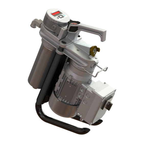
Page 27: Fig. 5 Mfu-10P With Contaminationsensor
HYDAC FILTER SYSTEMS GMBH Product and technical specifications | 3 Fig. 5: MFU-10P with ContaminationSensor BeWa MFU-10P 4391553c en-us web 27 / 120... -
Page 28: Proper/Designated Use
3 | Product and technical specifications HYDAC FILTER SYSTEMS GMBH 3.2 Proper/Designated Use The MFU filter unit is used as a portable filter unit for filling or emptying hydraulic systems, flushing or filtering hydraulic systems in the bypass flow, and recirculation with simulta- neous / without simultaneous filtration. -
Page 29: Improper Use Or Use Deviating From Intended Use
3.3 Improper use or use deviating from intended use Any other or extending use beyond this shall not be considered intended use. HYDAC FILTER SYSTEMS GMBH will assume no liability for any damage resulting from such use. This risk is borne solely by the owner. -
Page 30: Checking The Scope Of Delivery
– Check the packaging and the product for damage. Report any damage in transit to the forwarding agent or the HYDAC department in charge. – Check the scope of delivery for completeness. The filter unit is supplied without a mounted filter element or without mounted attachment parts. -
Page 31: Decoding The Name Plate
3.5 Decoding the name plate Identification details of the filter unit can be found on the name plates on the filter unit and the components. Always mention the part no. and the serial no. when contacting HYDAC. Fig. 6: Decoding the name plate Item Description... -
Page 32: Model Code
3 | Product and technical specifications HYDAC FILTER SYSTEMS GMBH 3.5.1 Model Code The filter unit is defined by the following model code: MFU - 15 E 9 - S M - F E / - Series MFU = Mobile Filter Unit... -
Page 33: Technical Data
HYDAC FILTER SYSTEMS GMBH Product and technical specifications | 3 3.6 Technical data If you are aware of the technical data of the product, you will be able to use it optimally. This section contains the technical details for the product:... -
Page 34: Tab. 4 Technical Data
3 | Product and technical specifications HYDAC FILTER SYSTEMS GMBH MFU-10P Permitted air during storage Clean, salt-free air, not near oxidizing substances (rust film) Storage duration Indefinite. Before the unit is started up again after being stored for more than two years, we recommend replacing all seals and especially the hoses. -
Page 35: Dimensions And Hydraulic Shematic
HYDAC FILTER SYSTEMS GMBH Product and technical specifications | 3 3.7 Dimensions and Hydraulic shematic The dimensions and hydraulic diagrams of the various product variants can be found below. Check the model code on the name plate of the filter unit. -
Page 36: Mfu-10P9 - Dimensions / Hydraulic Diagram
3 | Product and technical specifications HYDAC FILTER SYSTEMS GMBH 3.7.1.1 MFU-10P9 - Dimensions / hydraulic diagram The filter unit with AC electric motor has the following dimen- sions: Fig. 8: 4216883 - EBZ MFU-10P9-Sx-FE - AC All dimensions in mm. -
Page 37: Fig. 9 4216883 - Ebz Mfu-10P9-Sx-Fe - Dc
HYDAC FILTER SYSTEMS GMBH Product and technical specifications | 3 The filter unit with DC electric motor has the following dimen- sions: Fig. 9: 4216883 - EBZ MFU-10P9-Sx-FE - DC All dimensions in mm. BeWa MFU-10P 4391553c en-us web 37 / 120... -
Page 38: Fig. 10 Hydraulic Diagram Mfu-10P
3 | Product and technical specifications HYDAC FILTER SYSTEMS GMBH Hydraulic circuit: Fig. 10: Hydraulic diagram MFU-10P 38 / 120 BeWa MFU-10P 4391553c en-us web... -
Page 39: Design And Function
HYDAC FILTER SYSTEMS GMBH Product and technical specifications | 3 3.8 Design and function The following components/operating elements can be found on the filter unit: Fig. 11: Components MFU-10 P IN Inlet OUT Outlet BeWa MFU-10P 4391553c en-us web 39 / 120... - Page 40 3 | Product and technical specifications HYDAC FILTER SYSTEMS GMBH 30 Name plate of the filter unit 110 Connector head 111 Transport handle 115 Vane pump 132 Cable holder 133 Clogging indicator / back-pressure indicator 140 Pressure relief valve 180 Pressure relief valve for the ContaminationSensor...
-
Page 41: Transportation And Storage
HYDAC FILTER SYSTEMS GMBH Transportation and storage | 4 4 Transportation and storage You will find the respective notice on the prevention of damage to the product during transport or storage in this chapter. Empty the filter unit fully before transporting it or putting it into storage. -
Page 42: Storing The Filter Unit (>6 Months)
4 | Transportation and storage HYDAC FILTER SYSTEMS GMBH Store the filter unit upright in a clean and dry (condensation- free) space. The permissible storage conditions are given in Chapter Technical data [} 33]. 4.1 Storing the filter unit (>6 months) You will find the respective information on the prevention of damage to the filter unit during storage (>6 months) in this... -
Page 43: Transporting/Storing The Filter Unit With Hoses And Lances
HYDAC FILTER SYSTEMS GMBH Transportation and storage | 4 4.2 Transporting/storing the filter unit with hoses and lances If the filter unit is equipped with the hoses including lances from the accessories, here, you will find tips and options to place the lances during transport and storage. -
Page 44: Fig. 14: Storing The Mfu - Version 2
4 | Transportation and storage HYDAC FILTER SYSTEMS GMBH Insert the two lances into one another in the bracket on the filter unit. Version 2 can be stored only when the feet are parallel to each other. Fig. 14: Storing the MFU – Version 2... -
Page 45: Setting Up / Assembly / Integration Of The Filter Unit
HYDAC FILTER SYSTEMS GMBH Setting up / assembly / integration of the filter unit | 5 5 Setting up / assembly / integration of the filter unit Observe the following notices for mounting the filter unit. NOTICE There is a risk of the unit tipping or slipping away due to vibra- tions The filter unit will be damaged. -
Page 46: Fig. 15 Increasing The Stability/Adjusting The Feet
5 | Setting up / assembly / integration of the filter unit HYDAC FILTER SYSTEMS GMBH Fig. 15: Increasing the stability/adjusting the feet If the feet are not locked in the intended positions of 0° or 44°, the filter unit can tip. Only use the intended positions of 0° or 44°... -
Page 47: Fig. 16: Adjusting The Feet 0°⇨ 44
HYDAC FILTER SYSTEMS GMBH Setting up / assembly / integration of the filter unit | 5 Fig. 16: Adjusting the feet 0°⇨ 44° To adjust both feet from 0° to 44°, proceed as follows: 1. Fully unscrew both screws counterclockwise with an Allen key. -
Page 48: Fig. 17: Adjusting The Feet 44°⇨ 0
5 | Setting up / assembly / integration of the filter unit HYDAC FILTER SYSTEMS GMBH Fig. 17: Adjusting the feet 44°⇨ 0° To adjust both feet from 44° to 0°, proceed as follows: 4. Fully unscrew both screws counterclockwise with an Allen key. -
Page 49: Avoiding Siphoning
HYDAC FILTER SYSTEMS GMBH Setting up / assembly / integration of the filter unit | 5 5.2 Avoiding siphoning If there is a height difference ΔH between the suction side and pressure side container side / system, the low lying line can develop a suction effect and trigger the siphoning effect between the communicating containers / systems. -
Page 50: Avoiding The Mixing Of Oils - Emptying The Filter Unit
5 | Setting up / assembly / integration of the filter unit HYDAC FILTER SYSTEMS GMBH 5.3 Avoiding the mixing of oils - Emptying the filter unit If you want to use the same oil for operation as in the previous operation, the mixing of oils is not critical. -
Page 51: Making The Electrical Connections
HYDAC FILTER SYSTEMS GMBH Setting up / assembly / integration of the filter unit | 5 5.4 Making the electrical connections Depending on the version, the filter unit has different electric motors (e.g. different voltage/performance/number of phases, with/without power plug etc.). -
Page 52: Filter Unit Without Power Plug/Without Connection Cable
5 | Setting up / assembly / integration of the filter unit HYDAC FILTER SYSTEMS GMBH 5.4.1 Filter unit without power plug/without connection cable Depending on the version, the filter unit has neither a power plug nor a connection cable. Connect up the filter unit with a suitable connection cable and/or power plug. - Page 53 HYDAC FILTER SYSTEMS GMBH Setting up / assembly / integration of the filter unit | 5 ð The motor pump group begins to pump. 6. Switch the filter unit off at the main switch. O The filter unit is electrically connected.
- Page 54 5 | Setting up / assembly / integration of the filter unit HYDAC FILTER SYSTEMS GMBH 5.4.3 Connecting filter units with a power plug for 400 V AC, 3 phases The unit with a 3-phase electric motor is fitted with a main switch, motor protection and connection plug.
-
Page 55: Connecting The Suction/Pressure Port
HYDAC FILTER SYSTEMS GMBH Setting up / assembly / integration of the filter unit | 5 5.5 Connecting the suction/pressure port Install the filter unit securely in a system/an assembly, take the pressure loss into account with the piping or hose system. You will find the respective formula to calculate the pressure loss. - Page 56 5 | Setting up / assembly / integration of the filter unit HYDAC FILTER SYSTEMS GMBH – Ensure that the connecting lines (suction side/pressure side) do not transfer any voltage or vibrations to the product. Use hoses or compensators if necessary.
-
Page 57: Attaching/Connecting The Suction/Pressure Hoses (Accessories)
HYDAC FILTER SYSTEMS GMBH Setting up / assembly / integration of the filter unit | 5 5.6 Attaching/connecting the suction/pressure hoses (accessories) The suction/pressure hoses from the filter unit Accessories list [} 106] are matched to the filter unit. If you use different connection hoses, take into account the pressure loss when connecting suction/pressure hoses. -
Page 58: Commissioning The Filter Unit
5 | Setting up / assembly / integration of the filter unit HYDAC FILTER SYSTEMS GMBH 5.7 Commissioning the filter unit When you have checked the points listed here and can answer them with OK, the filter unit is ready for operation. - Page 59 HYDAC FILTER SYSTEMS GMBH Setting up / assembly / integration of the filter unit | 5 10. Switch the filter unit on and monitor the suction action via the transparent suction hose. If the filter unit does not pump any fluid after a max. of 5 minutes of oper- ation, switch the filter unit off.
-
Page 60: Manual Operation
6 | Manual operation HYDAC FILTER SYSTEMS GMBH 6 Manual operation Select the desired operating mode as described in Chapter Selecting the operating modes [} 62]. Connect the suction port / pressure port to the containers or devices to be cleaned and switch on the filter unit using the main switch or switch on the compressed-air supply. -
Page 61: Switching The Filter Unit On Or Off/Emergency-Stop
HYDAC FILTER SYSTEMS GMBH Manual operation | 6 6.1 Switching the filter unit on or off/EMERGENCY- STOP 1. Switch the filter unit on at the main switch to operate it. ð The filter unit starts pumping. 2. Switch the filter unit off at the main switch. -
Page 62: Selecting The Operating Modes
6 | Manual operation HYDAC FILTER SYSTEMS GMBH 6.3 Selecting the operating modes Select the optimal operating mode for your requirement. In order to do this, use a suitable filter element (900) or an empty element (910). Details for insertion or exchanging this can be found in Chapter Changing the filter element [} 80]. -
Page 63: Recirculation With Filtration/Dewatering
HYDAC FILTER SYSTEMS GMBH Manual operation | 6 6.3.1 Recirculation with filtration/dewatering For the operating mode recirculation with filtration orrecircu- lation with filtration/dewatering use the respective filter element (900) with the required filtration rating. An overview of the available filter elements with their filtration rating (900) can be found in Chapter Finding spare parts/accessories [} 101]. - Page 64 6 | Manual operation HYDAC FILTER SYSTEMS GMBH 6. Release the pressure hose at the quick coupling, see Removing/installing the quick coupling [} 86]. 7. Empty the contents of the pressure hose into the oil tank/container. 8. Empty the contents of the suction hose into the oil tank/ container.
-
Page 65: Circulation Pumping Without Filtration
HYDAC FILTER SYSTEMS GMBH Manual operation | 6 6.3.2 Circulation pumping without filtration In operating mode Recirculation without filtration, replace the filter element (900) with an empty element (910). A suitable empty element (910) can be found in Chapter Finding spare parts/accessories [} 101] Fig. 24: Empty element... - Page 66 6 | Manual operation HYDAC FILTER SYSTEMS GMBH 7. Release the pressure hose at the quick coupling, see Removing/installing the quick coupling [} 86]. 8. Empty the contents of the pressure hose into the oil tank/container. 9. Empty the contents of the suction hose into the oil tank/ container.
-
Page 67: Cleaning Up To The Required Cleanliness Class
HYDAC FILTER SYSTEMS GMBH Manual operation | 6 6.3.3 Cleaning up to the required cleanliness class To clean up to the required cleanliness class , proceed as follows. Use the respective filter element (900) with the required Filtration rating. An over-view of the available filter elements with Filtration rating (900) can be found in chapter Finding spare parts/accessories [} 101]. - Page 68 6 | Manual operation HYDAC FILTER SYSTEMS GMBH 2. Connect the pressure hose to the oil tank/container and fit the pressure hose in it and also secure it against falling out. 3. Connect the filter unit to the voltage source.
-
Page 69: Operation With Accessories
HYDAC FILTER SYSTEMS GMBH Manual operation | 6 6.4 Operation with accessories In order to adapt the filter unit to your requirements, you can select some items from the accessories list. While using accessories, the technical framework conditions can change in some cases such as the maximum permissible viscosity short time duty instead of continuous operation, etc. -
Page 70: Using A Flow Rate Meter
6 | Manual operation HYDAC FILTER SYSTEMS GMBH 6.4.2 Using a flow rate meter Containers and plants can be precisely filled with the flow rate meter. After a reset (RESET), the large digital display shows you the currently filled volume. -
Page 71: Using A Suction Line Filter On The Suction Hose
HYDAC FILTER SYSTEMS GMBH Manual operation | 6 6.4.4 Using a suction line filter on the suction hose With a suction line filter on the suction hose, even very dirty fluids can be suctioned. While doing so, they protect the pump and the internally installed protective screen from blocking up quickly due to too much dirt. -
Page 72: Rectifying Malfunctions
7 | Rectifying malfunctions HYDAC FILTER SYSTEMS GMBH 7 Rectifying malfunctions In order to get quick and immediate assistance in the case of errors, you will find the most often occurring errors with their cause and remedy with suitable specialist personnel in this chapter. - Page 73 HYDAC FILTER SYSTEMS GMBH Rectifying malfunctions | 7 Error Cause(s) Rectification There is air in Fill the vane the suction line pump through and the vane the suction hose/ pump. quick coupling. The viscosity of Check the the fluid is too viscosity of the high.
-
Page 74: Tab. 5 Error/Cause/Rectification
7 | Rectifying malfunctions HYDAC FILTER SYSTEMS GMBH Error Cause(s) Rectification Heat the fluid to achieve the permissible viscosity. Leaks in the Wrong, missing, Check the unit / filter or defective sealing ring of housing. sealing ring. the filter element. - Page 75 HYDAC FILTER SYSTEMS GMBH Rectifying malfunctions | 7 Error Cause(s) Rectification The vane pump Check the quick draws in air. The connect coupling quick coupling is for leaks. possibly not firmly tightened. Air is being The pressure mixed in the hose or the tank.
- Page 76 7 | Rectifying malfunctions HYDAC FILTER SYSTEMS GMBH Error Cause(s) Rectification direction opposite to the flow direction. Check the vane ContaminationS pump for proper ensor does not functioning. recognize flow. Switch the unit Remove the ContaminationS ContaminationS ensor is blocked.
-
Page 77: Performing Maintenance
HYDAC FILTER SYSTEMS GMBH Performing Maintenance | 8 8 Performing Maintenance For a long, trouble-free service life of the product, regular maintenance activities are required. This chapter contains the description of the required mainte- nance activities and the qualifications of the staff needed to carry out these tasks. -
Page 78: Maintenance Table
8 | Performing Maintenance HYDAC FILTER SYSTEMS GMBH 8.1 Maintenance table Additional infor- mation Observe the optical clogging indicator Checking/ cleaning the protective screen Removing/ installing the protective screen 8.4.1 Removing/ mounting the push-in protective screen 8.4.2 Removing/ installing the... - Page 79 HYDAC FILTER SYSTEMS GMBH Performing Maintenance | 8 Additional infor- mation Changing the filter element Checking/ cleaning the protective screen 1 - Operating personnel; 2 - Specialist personnel – Mechanical BeWa MFU-10P 4391553c en-us web 79 / 120...
-
Page 80: Changing The Filter Element
8 | Performing Maintenance HYDAC FILTER SYSTEMS GMBH 8.2 Changing the filter element Filter elements wear out due to the absorption of solid particles and / or the dissolved water in the fluid. The service life of a filter element depends on the solid particle contamination in the fluid / dissolved water and also the filtration rating. - Page 81 HYDAC FILTER SYSTEMS GMBH Performing Maintenance | 8 Filter element Empty element Proceed as follows for replacing the filter element: 1x wrench = 24 mm 1x torque wrench 1. With the filter unit switched on, remove the suction hose from the housing and aspirate air.
- Page 82 8 | Performing Maintenance HYDAC FILTER SYSTEMS GMBH 5. Loosen the filter bowl by turning it counterclockwise. If required, use a wrench = 24 mm. 6. Unscrew the filter bowl by turning it counterclockwise by hand. NOTICE! A small amount of fluid will drip out of the connector head and will collect in the drip tray.
- Page 83 HYDAC FILTER SYSTEMS GMBH Performing Maintenance | 8 9. Clean the sealing surface on the connector head and the filter bowl. Also clean the inside of the filter bowl. 10. Insert the new filter element or empty element into the filter bowl.
- Page 84 8 | Performing Maintenance HYDAC FILTER SYSTEMS GMBH 13. Fill the filter element fully with the fluid to be conveyed to ensure protection against dry-running. 14. Place the filter bowl with the filter element from the bottom to the connector head.
- Page 85 HYDAC FILTER SYSTEMS GMBH Performing Maintenance | 8 19. Switch on the filter unit and check for any leaks. O The replacement of the filter element is now complete. BeWa MFU-10P 4391553c en-us web 85 / 120...
-
Page 86: Removing/Installing The Quick Coupling
8 | Performing Maintenance HYDAC FILTER SYSTEMS GMBH 8.3 Removing/installing the quick coupling For transportation or for cleaning/changing the strainer, the suction hose must be removed. In the following, you can read about the procedure for the disassembly/assembly of the quick coupling at the suction connection. - Page 87 HYDAC FILTER SYSTEMS GMBH Performing Maintenance | 8 To remove it, proceed as follows: 1. Switch off the filter unit. 2. Remove the suction and pressure lances from the container and empty them. 3. Release the collet (952) on the quick coupling (951) counterclockwise by hand.
-
Page 88: Removing/Installing The Protective Screen
8 | Performing Maintenance HYDAC FILTER SYSTEMS GMBH 8.4 Removing/installing the protective screen The installed protective screen protects the pump from coarse contamination which could cause damage. If the uptake capacity of the protective screen has been reached, the volu- metric flow through the filter unit reduces sharply. -
Page 89: Removing/Mounting The Push-In Protective Screen
HYDAC FILTER SYSTEMS GMBH Performing Maintenance | 8 8.4.1 Removing/mounting the push-in protective screen No tools are required. Fig. 29: Removing/mounting the push-in protective screen 100 Suction hose with quick coupling 700 Quick coupling on the filter unit 701 Seal ring for quick coupling 710 Protective screen, 300 µm... - Page 90 8 | Performing Maintenance HYDAC FILTER SYSTEMS GMBH Proceed as follows to install: 4. For assembly, insert the cleaned or new protective screen (710) up to the stop into the quick coupling on the connection (IN). 5. Insert the seal ring (701) in the quick coupling.
-
Page 91: Removing/Installing The Push-In Protective Screen
HYDAC FILTER SYSTEMS GMBH Performing Maintenance | 8 8.4.2 Removing/installing the push-in protective screen 1x screwdriver = 16x2 mm Fig. 30: Removing/Installing the push-in protective screen For disassembly, proceed as follows: ü Switch off the filter unit and remove the lance from the reservoir and/or close the shut-off device in order to prevent any subsequent flow of the medium. - Page 92 8 | Performing Maintenance HYDAC FILTER SYSTEMS GMBH Proceed as follows to install: 4. Check the O-ring (712) for damage, replace it if necessary. 5. Insert the O-ring (712) in the connection. 6. Use the screwdriver = 16 x 2 mm to screw the protective screen (711) in the connection in clockwise direction.
-
Page 93: Checking/Cleaning The Protective Screen
HYDAC FILTER SYSTEMS GMBH Performing Maintenance | 8 8.5 Checking/cleaning the protective screen To protect the pump from large contaminant particles there is a protective screen in the suction port. Clean the strainer regu- larly. CAUTION Sharp-edged metallic chips/metallic particles in the protective... - Page 94 8 | Performing Maintenance HYDAC FILTER SYSTEMS GMBH O The assembly of the protective screen is complete 94 / 120 BeWa MFU-10P 4391553c en-us web...
-
Page 95: Protective Screen For Changing The Contaminationsensor
HYDAC FILTER SYSTEMS GMBH Performing Maintenance | 8 8.6 Protective screen for changing the ContaminationSensor The protective screen (531) protects the ContaminationSensor against clogging. Refer to Chapter Finding spare parts/acces- sories [} 101] for a suitable set of spare parts. NOTICE... - Page 96 8 | Performing Maintenance HYDAC FILTER SYSTEMS GMBH Fig. 31: Changing the protective screen on ContaminationSensor 521 O-ring 531 Protective screen 550 screws 561 Male connector for power supply to the ContaminationSensor For removal, proceed as follows: 1. Switch off the filter unit at the main switch and unplug the power connector.
- Page 97 HYDAC FILTER SYSTEMS GMBH Performing Maintenance | 8 4. Remove the ContaminationSensor in an upwards direction and observe the two O-rings (521). Remove the O-rings (521). 5. Use the screwdriver to rotate the protective screen (531) out in a counterclockwise direction.
- Page 98 8 | Performing Maintenance HYDAC FILTER SYSTEMS GMBH See also 2 Finding spare parts/accessories [} 101] 98 / 120 BeWa MFU-10P 4391553c en-us web...
-
Page 99: Decommissioning / Disposal
HYDAC FILTER SYSTEMS GMBH Decommissioning / Disposal | 9 9 Decommissioning / Disposal In the following chapters, you will be provided with information regarding temporary shutdown/final decommissioning and disposal of the product. 9.1 Temporary shutdown If the product is being temporarily shut down, the following... -
Page 100: A Appendix
Hotline, product support, Customer Service, Branches, service partners for maintenance, repair and spare parts can be found, always updated, on our homepagewww.hydac.com. HYDAC SYSTEMS & SERVICES GMBH Friedrichsthaler Str. 15, Werk 13 66450 Neunkirchen - Heinitz Germany... -
Page 101: Finding Spare Parts/Accessories
HYDAC FILTER SYSTEMS GMBH Appendix | A A.2 Finding spare parts/accessories Use only original spare parts for a long, trouble-free life cycle of the filter unit. When ordering spare parts and accessories make sure to always indicate the exact model code and the serial number. - Page 102 A | Appendix HYDAC FILTER SYSTEMS GMBH Fig. 33: Spare parts MFU-10 P 102 / 120 BeWa MFU-10P 4391553c en-us web...
- Page 103 – 2 feet including fastening material Set of drip pans consisting of: – Drip pan including fastening material Set of covers consisting of: – Cover plate HYDAC including the fastening material Protective screen for 3193968 ContaminationSensor consisting of: – Protective screen including seals...
-
Page 104: Tab. 8 Spare Parts List
A | Appendix HYDAC FILTER SYSTEMS GMBH Item Description Auxiliary Part no. Empty element, see Finding the filter elements [} 105] Tab. 8: Spare parts list *) On request. 104 / 120 BeWa MFU-10P 4391553c en-us web... -
Page 105: Finding The Filter Elements
HYDAC FILTER SYSTEMS GMBH Appendix | A A.2.1 Finding the filter elements For your application, select the appropriate filter element according to the filtration rating as well as the Filtering or filtering and dewatering function. The following filter elements are available for this:... -
Page 106: Accessories List
A | Appendix HYDAC FILTER SYSTEMS GMBH A.2.2 Accessories list In order to adapt the filter unit to your requirements optimally, the following accessories are available for your selection: Item Description Auxiliary Part no. Suction / Pressure hose with lances,... - Page 107 HYDAC FILTER SYSTEMS GMBH Appendix | A Item Description Auxiliary Part no. Suction / Pressure hose with lances, 1SN / 2TE 4270481 Hose length: 2.5 m / 5m, Lance length: 0.25 m Suction / Pressure hose with connections, PVC / PVC 4270482 Hose length: 2.5 m / 2.5m,...
- Page 108 A | Appendix HYDAC FILTER SYSTEMS GMBH Item Description Auxiliary Part no. Suction / Pressure hose with connections, 1SN / 2TE 4270483 Hose length: 2.5 m / 2.5m, Screw-in thread: M30x2 / M26x1,5 Suction / Pressure hose with connections, PVC / PVC 4270484 Hose length: 2.5 m / 5m, Screw-in thread: M30x2 / M26x1,5...
- Page 109 HYDAC FILTER SYSTEMS GMBH Appendix | A Item Description Auxiliary Part no. Suction line filter M30x2 4270560 (for installation on the suction hose only for viscosity <200 mm²/s) Set of lances consisting of: 4270559 - Suction lance, L = 1300 mm - Pressure lance, L = 1300 mm...
-
Page 110: Ec Declaration Of Conformity
Günter Harge Registered seat of company: 66280 Sulzbach / Saar +49 6897 509 1511 Court of Registration: Saarbrücken, HRB 17216 c/o HYDAC International GmbH, Industriegebiet, 66280 Sulzbach / Saar +49 6897 509 1394 guenter.harge@hydac.com Page 1 of 2 Value added tax identification number: DE 815001609... - Page 111 Executive director: Günter Harge Mathias Dieter, Dipl.Kfm. Wolfgang Haering +49 6897 509 1511 Registered seat of company: 66280 Sulzbach / Saar c/o HYDAC International GmbH, Industriegebiet, 66280 Sulzbach / Saar +49 6897 509 1394 guenter.harge@hydac.com Page 2 of 2 Telephone: Court of Registration: Saarbrücken, HRB 17216...
- Page 112 Table of Illustrations HYDAC FILTER SYSTEMS GMBH Table of Illustrations Overview / labeling of the title page ............Fig. 1 Safety marking, label / sign on the product ..........Fig. 2 Fire protection class B ................Fig. 3 Minimum distance for fire fighting.............
- Page 113 HYDAC FILTER SYSTEMS GMBH Table of Illustrations Removing/mounting the push-in protective screen ........Fig. 29 Removing/Installing the push-in protective screen ........Fig. 30 Changing the protective screen on ContaminationSensor ....... Fig. 31 Spare parts MFU-15 E / MFU-15 S ............101 Fig. 32 Spare parts MFU-10 P ................
- Page 114 Technical Data ..................Tab. 5 Error/cause/rectification................Tab. 6 Overview of the filter element / type of operation ........Tab. 7 HYDAC Service Germany ................ 100 Tab. 8 Spare parts list ..................103 Tab. 9 Filter elements for filtering ................ 105 Tab. 10 Filter elements for filtering and dewatering ..........
-
Page 115: Glossary
HYDAC FILTER SYSTEMS GMBH Glossary Glossary Cleanliness classes The 1 SN high-pressure hose has a Depending on the requirements and steel mesh insert and, on the inside, the sensor, the cleanliness classes is is made of oil-resistant synthetic of the solids contamination in the... - Page 116 Glossary HYDAC FILTER SYSTEMS GMBH DIMICRON temperature behavior). HLPD: with active substances for increasing The element technology of the corrosion protection, resistance to DIMICRON series is characterized aging and with additives with a by a high contamination retention detergent effect.
- Page 117 HYDAC FILTER SYSTEMS GMBH Glossary opposed to mineral oils, they have a meet the normal thermal loads. HM: lower aging resistance and can be with active substances for used under temperature loads only increasing corrosion protection, in a limited way.
-
Page 118: Index
Index HYDAC FILTER SYSTEMS GMBH Index Branch offices 100 General Terms and Conditions 12 Accessories list 106 Product support 100 Service 100 Service partners 100 Clogging indicator Terms of delivery 12 Clogging indicator, visual 61 Customer service 100 Imprint 2... - Page 119 HYDAC FILTER SYSTEMS GMBH Index Calculate hydraulic line 55 Ambient temperature range 33 Formula for 55 Emission sound pressure level 34 Pressure differential 55 Flow 33 protective screen Hydraulic connections 33 disassembling / assembling 88 IP protection class 34 Protective screen Operating fluids 33...
- Page 120 www.hydac.com...
Need help?
Do you have a question about the MFU-10P9S Series and is the answer not in the manual?
Questions and answers