
Related Manuals for SKF LINCOLN SP


Summary of Contents for SKF LINCOLN SP
- Page 1 Assembly instructions SP/FH single-piston grease lubrication pump acc. to Machinery Directive 2006/42/EC Version 01 951-170-234-EN...
- Page 2 EC Declaration of Incorporation EC Declaration of Incorporation acc. to Machinery Directive 2006/42/EC, Appendix II Part 1 B The manufacturer, SKF Lubrication Systems Germany GmbH, Hockenheim Plant, 2. Industriestraße 4, DE - 68766 Hockenheim, hereby declares the conformity of the partly completed machinery...
-
Page 3: Masthead
Training Disclaimer of liability SKF Lubrication Systems Germany GmbH The manufacturer shall not be held liable for SKF conducts detailed training in order to damage resulting from: Address of manufacturer plants enable the maximum safety and efficiency. ○ Improper usage, assembly, operation,... -
Page 4: Table Of Contents
Table of contents Table of contents Masthead .....................3 Explanation of symbols and signs ...............6 Safety instructions .................8 Lubricants ................... 14 General safety instructions ..............8 General information ................14 General behavior when handling the product ........8 Selection of lubricants ................14 Intended use .................... - Page 5 Table of contents Assembly ..................22 Cleaning ..................31 General information ................22 Cleaning agents ..................31 Assembly location .................22 Exterior cleaning ...................31 6.2.1 Surface .....................22 Interior cleaning ..................31 Minimum mounting dimensions ............23 Maintenance ................32 Mounting equipment ................23 Mounting the single-piston grease lubrication pump ......24 Malfunctions ................
-
Page 6: Explanation Of Symbols And Signs
Explanation of symbols, signs, and abbreviations Explanation of symbols and signs General warning Crushing hazard Risk of slipping Risk of electrical shock Unlock the product General notes Unauthorized persons must be Disposal, recycling kept away Warning level Consequence Probability Symbol Meaning DANGER Death, serious injury Immediate... - Page 7 Explanation of symbols, signs, and abbreviations Abbreviations and conversion factors approx. approximately °C degrees Celsius °F degrees Fahrenheit i.e. that is Kelvin ounce incl. including Newton fl. oz. Fluid ounce min. minimum hour inch max. maximum second pound per square inch minute sq.in.
-
Page 8: Safety Instructions
1. Safety instructions 1. Safety instructions 1.1 General safety instructions 1.2 General behavior when handling the product ○ The operator must ensure that the in- ○ The product may only be used in aware- ○ Responsibilities for different activities structions are read by all persons tasked with working on the product or who ness of the potential dangers, in proper must be clearly defined and observed. -
Page 9: Intended Use
1. Safety instructions 1.3 Intended use 1.6 Inspections prior to delivery ○ Use to feed, forward, or store hazardous Feed lubricants only in compliance with the The following tests were performed prior to specifications, technical data, and limits pre- substances and mixtures as defined in delivery: sented in this manual. -
Page 10: Notes On The Rating Plate
The rating plate is located on the front side of the product. To avoid loss of this data in case a rating plate becomes illegible, these required characteristics of the pump should be entered below in the manual. Example rating plate SKF Lubrication Systems Germany GmbH 764-000-0004 Schmierpumpe SP/FH 0,6M1A2 731... -
Page 11: Note On Ce Marking
1. Safety instructions 1.11 Instruction of outside itters 1.9 Note on CE marking 1.10 Persons authorized to use the product Before commencing work, the operator must inform outside fitters of the opera- Note on Pressure Equipment Directive tional safety regulations, applicable accident 1.10.1 Operator 2014/68/EU prevention regulations, and the functions of... -
Page 12: Operation
1. Safety instructions 1.13 Operation The following must be observed during depressurized, and secured against un- The operating and ambient conditions commissioning and operation: authorized activation. at the place of use. ○ All information within this manual and ○ Take appropriate measures to ensure that ○... -
Page 13: Initial Commissioning, Daily Startup
1. Safety instructions 1.17 Residual risks 1.15 Initial commissioning, daily startup Ensure that: Possible in Residual risk Avoidance / Remedy lifecycle Unauthorized persons must be kept away. ○ All safety mechanisms are fully present Personal injury / property dam- Nobody is allowed to be present below hoisted and functional. -
Page 14: Lubricants
2. Lubricants 2. Lubricants 2.1 General information 2.2 Selection of lubricants SKF Lubrication Systems considers lubri- Lubricants are used specially for specific Only lubricants specified for the cants to be an element of system design. applications. To fulfill the task, lubricants... -
Page 15: Material Compatibility
Lubricants can be tested in the company's laboratory for suitability for pumping in cen- tralized lubrication systems (e.g., "bleeding"). Please contact SKF if you have further ques- tions regarding lubricants. An overview of the lubricants we have tested is available on request. -
Page 16: Overview, Functional Description
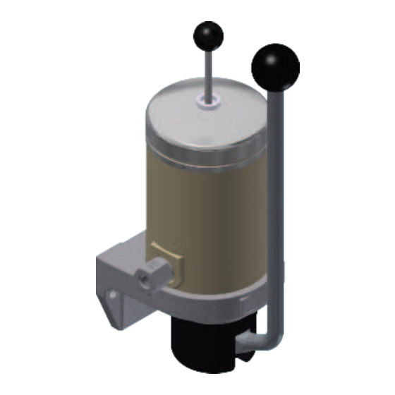
3. Overview, functional description 3. Overview, functional description 3.1 SP/FH components Overview of SP/FH, Fig. 1 Ball knob SP/FH without pressure relief valve Hand lever Line terminal (lubricant outlet) Reservoir Dip stick with grease follower plate Pump body Pressure relief valve Relief groove SP/FH with pressure relief valve 10 Inlet chamber... -
Page 17: Sp/Fh Operation
3. Overview, functional description 3.2 SP/FH operation 3.2.1 Without pressure relief valve Design A2/A4, Fig. 2 (pump designs A2/A4) See Figure 1 Behavior in a See Figures 1 and 2 pressure stroke CAUTION Pulling the hand lever (2) performs one pressure stroke. -
Page 18: With Pressure Relief Valve (Pump Designs A1/A3)
3. Overview, functional description 3.2.2 With pressure relief valve (pump designs A1/A3) See Figures 1 and 3 presses the lubricant to the lubricant outlet prevents the lubricant from flowing back. At Pulling the hand lever (2) performs one (12) via the opened check valve (11) and the same time, the inlet chamber refills with pressure stroke. -
Page 19: Technical Data
4. Technical data 4. Technical data 4.1 Technical data General Mounting position Vertical Reservoir capacity 0.6 l Line connection Thread M16x1.5 Weight Approx. 5 kg Ambient and lubricant temperature range -15°C to +80°C Hydraulic system Operating pressure Max. 100 or 150 bar Feedable lubricants Greases based on mineral oil ≥... -
Page 20: Order Code/Pump Designs
4. Technical data 4.2 Order code/pump designs Position of hand lever Operating Pressure With mounted feeder Order code Part No. Design relative to pressure relief lubricant outlet max.(bar) valve Type Part No. SP/FH 0,6M1A1 764-101-1110 SP/FH 0,6M2A1 764-101-1120 SP/FH 0,6M3A1 764-101-1130 SP/FH 0,6M1A2 764-000-0004... -
Page 21: Delivery, Returns, Storage
5. Delivery, returns, storage 5. Delivery, returns, storage 5.3 Storage 5.1 Delivery ○ Protected from nearby sources of heat After receipt of the shipment, it must be inspected for any shipping damage and for or cold Before usage, check products for completeness according to the shipping doc- ○... -
Page 22: Assembly
Damage to lines hand lever may be performed Before installation, ensure that no supply sembly work. only be SKF service staff. lines can be damaged by the installation. ○ The product must not be installed within range of moving parts. -
Page 23: Minimum Mounting Dimensions
6. Assembly 6.3 Minimum mounting dimensions 6.4 Mounting equipment Mounting equipment provided by customer: IMPORTANT NOTE ○ 2 M8 screws (strength class 8.8) acc. to DIN EN ISO 4017 Damage by failure to comply with ○ 2 M8 nuts, self-locking, acc. to minimum mounting dimensions The minimum mounting dimensions DIN EN ISO 10511... -
Page 24: Mounting The Single-Piston Grease Lubrication Pump
6. Assembly 6.5 Mounting the Assembly, Fig. 5 single-piston grease lubrication pump Section A Minimum mounting See Figure 5 dimensions: M1 = 518 mm M2 = 453 mm By default, the pump is secured to the M3 = 668 mm mounting surface through the flange bores Clearance for manual M4 = 276 mm... -
Page 25: Installation Example For A Single-Piston Grease Lubrication Pump With Progressive Feeder And Angle Bracket
6. Assembly 6.5.1 Installation example for a single- Installation example (100 bar design), Fig. 6 piston grease lubrication pump with progressive feeder and angle bracket See Figure 6 In this example, the pump is secured to the mounting surface through the flange bores (2x) on the angle bracket. -
Page 26: Connect The Lubricant Line
6. Assembly 6.6 Connect the lubricant line ○ If the system configuration requires that All components of the centralized lubrication CAUTION system must be designed for: the lubricant feeders be arranged below the main lubricant line, they should not ○ The maximum pressure that occurs Risk of slipping be placed at the end of the main lubricant ○... -
Page 27: Mounting The Lubricant Line To The Single-Piston Grease Lubrication Pump
6. Assembly 6.7 Mounting the lubricant line to the 6.9 Venting single-piston grease lubrication • Clean the area surrounding the pump. See Figure 5 pump Requirements for the venting process are • Clean the exterior of the reservoir See Figure 7 that all components have already been (see Chapter 9.2). -
Page 28: Commissioning
7. Commissioning All SKF pumps are checked for functionality with mineral oil prior to delivery. Mineral oil residue may become gummy if stored for extended periods. This applies in particular to storage in elevated ambient temperatures and/or if exposed to sunshine. Before startup after extended storage, a check must therefore be performed for gumming and any gummy elements must be cleaned (e.g., using petroleum). -
Page 29: Sp/Fh With Pressure Relief Valve (A1/A3)
7. Commissioning 7.3 SP/FH with pressure relief valve 7.3.3 Pressure relief time 7.4 SP/FH without pressure relief valve (A1/A3) (A2/A4) The pressure relief time for a system with a If the pump supplies one lubrication point 7.3.1 Lubrication process 10-meter-long main line and an ambient directly or multiple lubrication points via a temperature of + 10°C is approx. -
Page 30: Operation
See Chapter 6.8 for a description. Exercise caution when handling lubricants; immediately bind and remove any leaked lubricants. SKF products operate largely automatically. The activities required during normal op- eration are limited primarily to inspection of the fill level, timely refilling of lubricant, and cleaning the exterior of the product if contaminated. -
Page 31: Cleaning
The interior of the product must be cleaned if incorrect or contaminated lubricant is ac- cidentally filled. Always completely remove resi- Please contact SKF Customer Service. due of the cleaning agent on the product and rinse with clear wa- ter. This prevents the formation of alkaline deposits. -
Page 32: Maintenance
10. Maintenance Maintenance Careful and regular maintenance is required in order to detect and remedy possibly malfunctions in time. The specific intervals must always be determined by the operator according to the operating conditions and regularly reviewed and adapted where necessary. If necessary, copy the table for regular maintenance activities. Maintenance checklist Activity to be performed Visual leak test performed on connections... -
Page 33: Malfunctions
11. Malfunctions / 12. Repairs Malfunctions Repairs In cases of functional failure, always check whether all technical specifications have been WARNING adhered to in the existing operating conditions. Risk of injury At a minimum, the following safety Malfunctions table measures must be taken before Malfunction Possible cause Remedy... -
Page 34: Shutdown, Disposal
13. Shutdown, disposal Shutdown, disposal 13.1 Temporary shutdown 13.3 Disposal Temporary shutdown is performed by: Waste should be avoided or minimized to Plastic or metallic parts can be the extent possible. The disposal of prod- ○ Switching off the main machine disposed of as industrial waste. -
Page 35: Spare Parts, Accessories
14. Spare parts, accessories Spare parts, accessories The spare parts groups are used exclusively as replacement for defective parts identical in construction. No modifications to existing products using the spare parts are permitted. 14.1 Spare parts for SP/FH06...A1/A2/A3/A4 Overview of spare parts for SP/FH 0,6..A1/A2/A3/A4, Fig. 8 ... - Page 36 14. Spare parts, accessories Spare part order numbers Part Designation Pieces SP/FH 0,6..A1 SP/FH 0,6..A2 SP/FH 0,6..A3 SP/FH 0,6..A4 Flange 44-0617-2765 44-0617-2765 44-0617-2765 44-0617-2765 Reservoir 44-0254-2005 44-0254-2005 44-0254-2005 44-0254-2005 Pump body, complete 24-1557-3217 24-1557-3571 24-1557-3217 24-1557-3571 Cheese-head screw Z1 DIN912-M6X20-8.8 DIN912-M6X20-8.8 DIN912-M6X20-8.8 DIN912-M6X20-8.8...
- Page 37 14. Spare parts, accessories Spare part order numbers Part Designation Pieces SP/FH 0,6..A1 SP/FH 0,6..A2 SP/FH 0,6..A3 SP/FH 0,6..A4 Ball knob 25-6 Con,Type31,Black 95-2172-0319 95-2172-0319 95-2172-0319 95-2172-0319 Cap (polyamide) 44-1050-2011 44-1050-2011 44-1050-2011 44-1050-2011 Screw-in piece M16X1,5-M8 44-0159-2387 44-0159-2387 44-0159-2387 44-0159-2387 Sealing ring A16X22 DIN7603-CU 95-1631-7603 95-1631-7603...
-
Page 38: Spare Parts For Sp/Fh 0,6M1A4035 (Material Number 764-200-4037)
14. Spare parts, accessories 14.1.1 Spare parts for SP/FH 0,6M1A4035 (material number 764-200-4037) Overview of spare parts SP/FH 0,6M1A4035, Fig. 9 View X Feeder and feeder accessories -See documentation: Block feeder VPB, Document No. 1-3017-EN Progressive feeders of the series VP, VPK, VPB, Document No. 951-230-008-EN View A - 38 - 951-170-234-EN... - Page 39 14. Spare parts, accessories Spare part order numbers SP/FH 0,6M1A4035 Item Designation Pieces Order number Pump (SP/FH0,6M1A4029) 764-200-4031 Power lead from pump to feeder Cheese-head screw Z1 DIN912-M8x20-8.8 Flat washer 95-1084-6798 Check valve RHV8 (R1/4) 96-9008-0058 WV steel tubing 44-1751-2863 Banjo bolt M10X1 44-1821-2237 Housing XSWVE8...
-
Page 40: Spare Parts For Sp/Fh 0,6M1A4033 (Material Number 764-200-4035)
14. Spare parts, accessories 14.1.2 Spare parts for SP/FH 0,6M1A4033 (material number 764-200-4035) Overview of spare parts for SP/FH 0,6M1A4033, Fig. 10 Feeder with 6 outlets (standard) Consolidation of neighboring outlets towards the inlet Feeder with 2 outlets section: Remove the plug for the respective feeder section and close the outlet bore using a screw plug. - Page 41 14. Spare parts, accessories Spare part order numbers SP/FH 0,6M1A4033 Item Designation Pieces Order number Pump (SP/FH0,6M1A4032) 764-200-4034 Power lead from pump to feeder Cheese-head screw Z1 DIN912-M8x20-8.8 Flat washer 95-1084-6798 Check valve RHV8 (R1/4) 96-9008-0058 WV steel tubing 44-1751-2752 Banjo fitting 96-7108-0058 Screw M6x8...
-
Page 42: Accessories
Threaded bushing M16x1,5 WAF 17 44-0159-6790 Double tapered ring tube-8 44-0405-6524 10x1 Threaded bushing M16x1,5 tube-10 44-0159-6791 10x1 Double tapered ring tube-10 44-0405-6525 14.2.2 Other accessories See the SKF accessories catalog, 1-0103-EN, for further feeders and other accessories. - 42 - 951-170-234-EN Version 01... - Page 43 Notes...
- Page 44 Seals and Bearing Systems Over the course of more than a century, SKF has specialized in five fields of competence and acquired a Units wide range of application expertise. We utilize this experience to provide innovative solutions to OEMs and other manufacturers in practically all industrial sectors worldwide.Our five fields of competence are:...
Need help?
Do you have a question about the LINCOLN SP and is the answer not in the manual?
Questions and answers