
Subscribe to Our Youtube Channel
Related Manuals for SKF LINCOLN SP/FH


Summary of Contents for SKF LINCOLN SP/FH
- Page 1 Operating instructions SP/FH ATEX single-piston grease lubrication according to ATEX Directive 2014/34/EU pump with VPB ATEX feeder Version 02 951-180-075-EN...
-
Page 2: Eu Declaration
EC Declaration of Conformity EU Declaration of Conformity pursuant to ATEX Directive 2014/34/EU, Annex X The manufacturer, SKF Lubrication Systems GmbH, Hockenheim Plant, 2. Industriestraße 4, DE - 68766 Hockenheim, hereby declares the conformity of the device Designation: ATEX single-piston grease lubrication pump with VPB ATEX feeder... -
Page 3: Masthead
Masthead Manufacturer Disclaimer of liability Training SKF Lubrication Systems Germany GmbH SKF conducts detailed training in order to The manufacturer shall not be held liable for Address of manufacturer plants enable the maximum safety and efficiency. damage resulting from: ○ Improper usage, assembly, operation,... -
Page 4: Table Of Contents
Table of contents Table of contents EU Declaration ................... 2 1.21 Nullification of ATEX approval .............17 1.22 Operation in potentially explosive atmospheres .......17 Masthead ....................3 1.23 Explosion protection marking .............17 Explanation of symbols and signs .............. 6 1.24 Obligations of the operator ..............18 Safety instructions ................ - Page 5 Table of contents Delivery, returns, storage ............31 Cleaning ..................41 Delivery ....................31 Cleaning agents..................41 Return shipment ...................31 Exterior cleaning ...................41 Storage ....................31 Interior cleaning ..................41 Assembly ..................32 Maintenance ................42 General information ................32 Malfunctions ................43 Assembly location .................32 6.2.1 Surface .....................32 Repairs ..................
-
Page 6: Explanation Of Symbols And Signs
Explanation of symbols, signs, and abbreviations Explanation of symbols and signs General warning Risk of electrical shock Risk of slipping Hot surfaces Being drawn into machinery Crushing hazard Pressure injection Suspended load Electrostatic sensitive Potentially explosive Reserve Reserve components atmosphere Wear personal protective gear Wear personal protective gear Wear personal protective gear... - Page 7 Explanation of symbols, signs, and abbreviations Abbreviations and conversion factors regarding °C degrees Celsius °F degrees Fahrenheit approx. approximately Kelvin ounce i.e. that is Newton fl. oz. Fluid ounce incl. including hour inch min. minimum second pound per square inch max.
-
Page 8: Safety Instructions
1. Safety instructions 1. Safety instructions 1.1 General safety instructions ○ The operator must ensure that the in- ○ Unauthorized persons must be kept dition to these instructions, the statu- structions are read by all persons tasked tory regulations for accident prevention away. -
Page 9: Intended Use
1. Safety instructions 1.4 Foreseeable misuse of work and then inspected for proper Any usage of the product other than as 0.5 bar [7.25 psi] at their maximum per- function. specified in this manual is strictly prohibited. missible operating temperature Particularly prohibited are: ○... -
Page 10: Painting Plastic Components
1. Safety instructions 1.6 Modifications to the product 1.9 Referenced documents ○ Use of lubricants with temperatures Unauthorized modifications and changes In addition to this manual, the following above the maximum permissible ambient can have an unpredictable effect on safety. documents must be observed by the re- temperature. -
Page 11: Markings On The Product
Example rating plate Equipotential bonding ments of the applied Directives: ○ 2014/34/EU connections on the product SKF Lubrication Systems Germany GmbH Equipment and protective systems in- 764-200-4036 tended for use in potentially explosive II 3G Ex h IIB T4 Gc atmospheres. -
Page 12: Persons Authorized To Use The Product
1. Safety instructions 1.13 Persons authorized to use the pro- 1.13.3 Specialist in maintenance and 1.14 Instruction of outside fitters duct servicing in potentially explosive atmospheres Before commencing work, the operator 1.13.1 Operator This is a person competent due to qualified must inform outside fitters of the opera- A person competent due to training, knowl- technical education, training, and experi-... -
Page 13: Operation
1. Safety instructions 1.16 Operation 1.17 Transport, assembly, maintenance, malfunction, repair, shutdown, disposal ○ All relevant persons must be informed of The following must be observed during commissioning and operation: the activity prior to the start of this work. ○ All information within this manual and ○... -
Page 14: Initial Commissioning, Daily Startup
1. Safety instructions 1.18 Initial commissioning, daily startup ○ All components used must be designed ○ Adhere to the specified torques. Use Ensure that: ○ All safety mechanisms are fully present for: a calibrated torque wrench when - The maximum operating pressure tightening. -
Page 15: Cleaning
1. Safety instructions 1.19 Cleaning 1.20 Special safety instructions regarding explosion protection ○ There is a fire hazard from the use of ○ Always behave so as to avoid explosion ○ Inspect the product at regular intervals flammable cleaning agents. Use only non-flammable cleaning agents that are hazards. - Page 16 1. Safety instructions gas and dust groups and temperature machine containing the following infor- (e.g., due to heating of bearings on the classes. Light metal dusts, as a poten- mation: machine in the range of the ignition tially explosive ambient medium, are - Date temperature).
-
Page 17: Nullification Of Atex Approval
○ All information within this manual and rating plate. ○ Unauthorized alterations the information within the referenced documents ○ Use of non-original SKF spare/replace- ○ All laws and regulations that the operator ment components must observe ○ Failure to comply with this manual and ○... -
Page 18: Obligations Of The Operator
1. Safety instructions 1.24 Obligations of the operator fulfill the minimum explosion protection 1.24.1 Identification of hazards requirements. The operator ○ Documents the measures for explosion The operator must identify all hazards re- sulting from integration into the main ma- protection chine as well as the hazards at the machine’s ○... -
Page 19: Provision Of Necessary Information
1. Safety instructions 1.24.3 Provision of necessary information 1.24.4 Duty to provide instruction and training ○ Handling operating materials and clean- The operator must the relevant required in- The operator clearly defines the respon- structions available to all persons assigned sibilities of the personnel for operation, ing agents with operation, repair, and maintenance. -
Page 20: Residual Risks
1. Safety instructions 1.25 Residual risks Possible in Residual risk Avoidance / Remedy lifecycle Personal injury / property damage due Unauthorized persons must be kept away; nobody is allowed to be present below hoisted A, B, C, G, H, K to falling of hoisted parts parts. -
Page 21: Residual Atex Risks
1. Safety instructions 1.26 Residual ATEX risks Possible in Residual risk Avoidance / Remedy lifecycle Use in a potentially explosive atmo- Check the equipotential bonding for continuity before initial commissioning, after every repair, sphere without checking equipotential C, D, G and additionally at regular intervals defined by the operator bonding for electrical continuity Use with a damaged, incorrect, or miss-... - Page 22 1. Safety instructions Possible in Residual risk Avoidance / Remedy lifecycle Generation of electrostatic charges or sparks by C, D, E, F, G Secure parts against falling. if necessary, cover parts to avoid sparking dropping of parts Introduction of catalytic, unstable, or pyro- Ensure that none of these substances enter the potentially explosive atmosphere;...
-
Page 23: Lubricants
2.Lubricants 2. Lubricants 2.2 Selection of lubricants 2.1 General information SKF Lubrication Systems considers lubri- Only lubricants specified for the Lubricants are used specially for specific ap- cants to be an element of system design. product may be used plications. To fulfill the task, lubricants must The selection of a suitable lubricant should (see “Technical data”... -
Page 24: Material Compatibility
(e.g., "bleeding"). ○ Steel, gray cast iron, brass, copper, individual lubricants that meet Please contact SKF if you have further ques- the required specifications ac- aluminum tions regarding lubricants. cording to the manufacturer’s An overview of the lubricants we have ○... -
Page 25: Overview, Functional Description
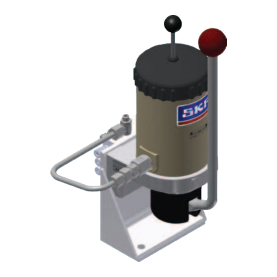
3. Overview, functional description 3. Overview, functional description 3.1 SP/FH components Overview of SP/FH, Fig. 1 Legend to Fig. 1 Ball knob Hand lever Feeder port Reservoir -MIN Dip stick with grease follower plate Pump body Inlet chamber Check valve Lubricant outlet (line connection) Vent plug Flange... -
Page 26: Sp/Fh Operation
3. Overview, functional description 3.2 SP/FH operation 3.3 SP/FH function Design A2/A4, Fig. Behaviour in a pressure stroke See Figure 2 See Figures 1 and 2 Pulling the hand lever (2) performs one CAUTION pressure stroke. The working piston (16) pushes against the spring force of the pres- Crushing hazard Be careful when actuating the hand... -
Page 27: Functional Description Of A Vpb Progressive Feeder
3. Overview, functional description 3.4 Functional description of a VPB progressive feeder See Figure 3 The task of the progressive feeder is to liably as defined. When all pistons have been tions for both outlets are determined by the consecutively distribute specified portions moved once to the left end position as well diameter and the travel of the piston. -
Page 28: Technical Data
4. Technical data 4. Technical data Protective marking for SP/FH ATEX single-piston grease lubrication pump with VPB ATEX block feeder II 3G Ex h IIB T4 Explosion protection marking Ambient and lubricant temperature range -20°C to +40°C 4.1 SP/FH technical data SP/FH single-piston grease lubrication pump Mounting position Vertical... -
Page 29: Vpb Technical Data
4. Technical data 4.2 VPB technical data ATEX -VPB progressive feeder, basic design Type Hydraulically controlled Mounting position Inlet and outlet threads VPBM (metric thread) M10x1 VPBG (inch thread) G1/8 Ambient temperature range -25 to +110°C Material Steel, galvanized, optional stainless Hydraulic system Operating pressure max.: Oil 200 bar, grease 300 bar... -
Page 30: Order Code/Pump Designs
4. Technical data 4.3 Order code/pump designs Position of hand lever relative Item number Order code Design Operating pressure, max. (bar) to lubricant outlet 764-200-4036 SP/FH 0,6M1A4034 1) A4 for pumps for direct supply or for progressive feeders (pumps with check valve) Position of hand lever relative to lubricant outlet, Fig. -
Page 31: Delivery, Returns, Storage
5. Delivery, returns, storage 5. Delivery, returns, storage 5.1 Delivery The following conditions apply to storage: ○ The permissible storage temperature After receipt of the shipment, it must be inspected for any shipping damage and for range corresponds to the operating tem- completeness according to the shipping doc- perature range (see “Technical data”). -
Page 32: Assembly
Before installation, ensure that no supply ○ The dip stick of the pump must be clearly only be SKF service staff. lines can be damaged by the installation. visible. ○ Follow the mounting position require-... -
Page 33: Minimum Mounting Dimensions
6. Assembly 6.3 Minimum mounting dimensions 6.4 Mounting equipment 6.5 Installation of the single-piston grease lubrication pump with pro- gressive feeder and angle bracket IMPORTANT NOTE Mounting equipment provided by customer: See Figure 5 Damage by failure to comply with mini- ○... - Page 34 6. Assembly Assembly, Fig. 5 Ø 11 Approx. 260 Approx. 98 "X" Drilling template Ø 11 (2x) -MIN View X Lubricant outlet Pipe Ø6 "A" Lubricant outlet Pipe Ø6 Minimum mounting View A dimensions: M1 = 450 mm M2 = 140 mm M3 = 460 mm M4 = 300 mm - 34 -...
-
Page 35: Establishing Equipotential Bonding Connection
6. Assembly 6.5.1 Establishing equipotential bonding connection Connection for equipotential bonding, Fig. 6 See Figure 6 All parts of the grounding concept must be properly present and connected with the main machine. The design of the conductor cross-section is defined by the customer. The product has an equipotential bonding connection (screw M6). -
Page 36: Connect The Lubricant Line
6. Assembly 6.6 Connect the lubricant line ○ The flow of lubricant should not be All components of the centralized lubrication 6.6.1 General information on line routing system must be designed for: impeded by the incorporation of sharp bends, angle valves, flap valves, seals ○... -
Page 37: Installation Of Lubricant Line On Vb Feeder
• If necessary, apply outlet screw unions or lubricants; immediately bind and • Fill the reservoir from above with a suit- SKF plug connectors to the threads of the able, clean lubricant to max. 20 mm be- remove any leaked lubricants. -
Page 38: Venting The Vpb Block Feeder And The Lubrication Lines
6. Assembly 6.8 Venting 6.8.2 Venting the VPB block feeder and the lubrication lines See Figure 7 SP/FH filling, venting, Fig. 7 6.8.1 Venting the SP/FG The progressive feeders are subjected to See Figure 7 functional monitoring using oil at the factory. It is possible that oil will discharge from the A requirement for the venting process is feeder at the start of commissioning. -
Page 39: Initial Commissioning
7. Initial commissioning All SKF pumps are checked for functionality with mineral oil prior to delivery. Mineral oil residue may become gummy if stored for extended periods. This applies in particular to storage in elevated ambient temperatures and/or if exposed to sunshine. Before startup after extended storage, a check must therefore be performed for gumming and any gummy elements must be cleaned. -
Page 40: Operation
See Chapter 6.7 for a description. pump’s actuation frequency to the pump. SKF products operate largely automatically. This must be determined in advance de- The activities required during normal op- pending on the particular project. -
Page 41: Cleaning
Always completely remove Please contact SKF Customer Service. residue of the cleaning agent on the product and rinse with clear The reservoir must be kept water. This prevents the forma- closed during cleaning. -
Page 42: Maintenance
10. Maintenance Maintenance Careful and regular maintenance is required in order to detect and remedy possibly malfunctions in time. The specific intervals must always be determined by the operator according to the operating conditions and regularly reviewed and adapted where necessary. If necessary, copy the table for regular maintenance activities. Maintenance checklist Activity to be performed Visual leak test performed on connections... -
Page 43: Malfunctions
11. Malfunctions Malfunctions In cases of functional failure, always check whether all technical specifications have been adhered to in the existing operating conditions. Malfunctions table Malfunction Possible cause Remedy No pressure Refill lubricant build-up in Lubricant reservoir empty (see Chapter 6.7, “Filling with lubricant”) lubrication system Vent the pump... -
Page 44: Repairs
ATEX Directives 2014/34/EU and 1999/92/EC. Apart from the replacement of defined spare parts, repairs may only be carried out by SKF ser- vice technicians. - 44 - 951-180-075-EN Version 02... -
Page 45: Shutdown, Disposal
13. Shutdown, disposal Shutdown, disposal 13.1 Temporary shutdown 13.2 Permanent shutdown, disassembly 13.3 Disposal Temporary shutdown is performed by: Waste should be avoided or minimized to the extent possible. The disposal of prod- CAUTION ○ Switching off the main machine ucts contaminated with lubricant must be performed by a recognized waste disposal Risk of slipping... -
Page 46: Spare Parts, Accessories
14. Spare parts Spare parts, accessories The spare parts groups are used exclusively as replacement for defective parts identical in construction. No modifications to existing products using the spare parts are permitted. 14.1 SP/FH spare parts Overview of SP/FH spare parts "X"... - Page 47 14. Spare parts FP/FH grease lubrication pump, spare parts order numbers Item Designation Pieces Order No. Flange 44-0617-2765 Reservoir 44-0254-2005 Pump body, complete 24-1557-3572 Screw-in piece M16X1,5-M8 44-0159-2387 Sealing ring A16X22 DIN7603-CU 95-1631-7603 Cheese-head screw Z1 DIN912-M6X20-8.8 Sealing ring DIN7603-A6X10-CU Sealing ring 17,2X22,8X7 44-0411-2132 O-ring...
- Page 48 14. Spare parts SP/FH grease lubrication pump and block feeder spare part order numbers Item Designation Pieces Order No. Check valve RHV8 96-9008-0058 Angle bracket, complete 24-2254-2007 Cheese-head screw Z1 DIN912-M8X20-8.8 Washer J8,4 D6798 Z1 95-1084-6798 O-ring WVN501-20X2 VPB ATEX block feeder BLOCK-VERT.
-
Page 49: Accessories
14. Spare parts 14.2 Accessories 14.2.1 Accessories for lubrication line connection Outlet screw unions for VPB progressive feeder Order Number Designation VPBM VPBG Straight connector DIN2353, Ø 4 mm, conical, LL 404-403 Straight connector DIN2353, Ø 4 mm, LL 404-403W Straight connector DIN2353, Ø... -
Page 50: Accessories
WV-RO8X1VERZI Banjo bolt M10X1 44-1821-2237 Housing XSWVE8 96-7153-0058 Cutting sleeve 96-5708-0058 Union nut 96-5608-0058 Screw M6x8 95-0608-0912 Edge sealing ring DKAZ 96-9576-0058 See the SKF accessories catalogue, 1-0103-EN, for further feeders and other accessories. - 50 - 951-180-075-EN Version 02... - Page 51 Notes...
- Page 52 951-180-075-EN November 2019 Version 02 SKF Lubrication Systems Germany GmbH Walldorf Plant Heinrich-Hertz-Straße 2-8 DE - 69190 Walldorf Tel. +49 (0)62 27 33-0 Fax +49 (0)62 27 33-259 E-mail: Lubrication-germany@skf.com www.skf.com/lubrication...
Need help?
Do you have a question about the LINCOLN SP/FH and is the answer not in the manual?
Questions and answers