
Related Manuals for YASKAWA System 300S+ CPU 315-4PN43


Summary of Contents for YASKAWA System 300S+ CPU 315-4PN43
- Page 1 System 300S CPU | 315-4PN43 | Manual HB140 | CPU | 315-4PN43 | en | 18-02 SPEED7 CPU 315PN ECO...
- Page 2 YASKAWA Europe GmbH Hauptstraße 185 65760 Eschborn Germany Tel.: +49 6196 569-300 Fax: +49 6196 569-398 Email: info@yaskawa.eu.com Internet: www.yaskawa.eu.com 315-4PN43_000_CPU 315PN ECO,4,EN - © 2018...
-
Page 3: Table Of Contents
System 300S Table of contents Table of contents General........................6 1.1 Copyright © YASKAWA Europe GmbH............6 1.2 About this manual..................... 7 1.3 Safety information..................... 8 Basics........................9 2.1 Safety information for users................9 2.2 Operating structure of a CPU................. 10 2.2.1 General...................... - Page 4 Table of contents System 300S 5.10.1 Transfer via MPI..................49 5.10.2 Transfer via Ethernet................. 50 5.10.3 Transfer via memory card................51 5.11 Accessing the web server................51 5.12 Operating modes..................57 5.12.1 Overview....................57 5.12.2 Function security..................59 5.13 Overall reset....................60 5.14 Firmware update...................
- Page 5 9.4 TIA Portal - Hardware configuration - Ethernet PG/OP channel....128 9.5 TIA Portal - Hardware configuration - PG/OP via PROFINET...... 130 9.6 TIA Portal - Setting VIPA specific CPU parameters........132 9.7 TIA Portal - Yaskawa-Include library............136 9.8 TIA Portal - Project transfer................137 Appendix......................139 A System specific event IDs................
-
Page 6: General
This material is protected by copyright laws. It may not be reproduced, distributed, or altered in any fashion by any entity (either internal or external to Yaskawa) except in accordance with applicable agreements, contracts or licensing, without the express written consent of Yaskawa and the business management owner of the material. -
Page 7: About This Manual
Tel.: +49 6196 569 500 (hotline) Email: support@yaskawa.eu.com 1.2 About this manual Objective and contents This manual describes the SPEED7 CPU 315-4PN43 of the System 300S from Yaskawa. It contains a description of the construction, project implementation and usage. Product Order no. -
Page 8: Safety Information
General System 300S Safety information 1.3 Safety information Applications conforming The system is constructed and produced for: with specifications communication and process control general control and automation tasks industrial applications operation within the environmental conditions specified in the technical data installation into a cubicle DANGER! This device is not certified for applications in... -
Page 9: Basics
System 300S Basics Safety information for users Basics 2.1 Safety information for users Handling of electrostatic The modules make use of highly integrated components in MOS-Technology. These com- sensitive modules ponents are extremely sensitive to over-voltages that can occur during electrostatic dis- charges. -
Page 10: Operating Structure Of A Cpu
Basics System 300S Operating structure of a CPU > Operands 2.2 Operating structure of a CPU 2.2.1 General The CPU contains a standard processor with internal program memory. In combination with the integrated SPEED7 technology the unit provides a powerful solution for process automation applications within the System 300S family. - Page 11 System 300S Basics Operating structure of a CPU > Operands Process image and The user application can quickly access the process image of the inputs and outputs PIO/ periphery PII. You may manipulate the following types of data: individual Bits Bytes Words Double words...
-
Page 12: Cpu 315-4Pn43
SIMATIC Manager or TIA Portal from Siemens. Here the instruction set of the S7-400 from Siemens is used. Modules and CPUs of the System 300S from Yaskawa and Siemens may be used at the bus as a mixed configuration. The user application is stored in the battery buffered RAM or on an additionally plug- gable storage module. - Page 13 System 300S Basics CPU 315-4PN43 Data memory (50% of the work memory) Work memory 512kbyte – There is the possibility to extend the work memory to its maximum printed capacity 1MB by means of a memory extension card. Integrated PROFINET IO The CPU has an integrated PROFINET IO controller which is to be configured via the controller PROFINET sub module in the hardware configurator from Siemens.
-
Page 14: General Data
Basics System 300S General data 2.4 General data Conformity and approval Conformity 2014/35/EU Low-voltage directive 2014/30/EU EMC directive Approval Refer to Technical data others RoHS 2011/65/EU Restriction of the use of certain hazardous substances in electrical and electronic equipment Protection of persons and device protection Type of protection IP20 Electrical isolation... -
Page 15: Use In Difficult Operating Conditions
System 300S Basics General data > Use in difficult operating conditions Mounting conditions Mounting place In the control cabinet Mounting position Horizontal and vertical Standard Comment Emitted interference EN 61000-6-4 Class A (Industrial area) Noise immunity EN 61000-6-2 Industrial area zone B EN 61000-4-2 8kV at air discharge (degree of severity 3),... -
Page 16: Assembly And Installation Guidelines
Assembly and installation guidelines System 300S Installation dimensions Assembly and installation guidelines 3.1 Installation dimensions Dimensions Basic enclo- 2tier width (WxHxD) in mm: 80 x 125 x 120 sure Installation dimensions HB140 | CPU | 315-4PN43 | en | 18-02... -
Page 17: Assembly Standard Bus
System 300S Assembly and installation guidelines Assembly standard bus 3.2 Assembly standard bus General The single modules are directly installed on a profile rail and connected via the backplane bus connector. Before installing the modules you have to clip the backplane bus con- nector to the module from the backside. - Page 18 Assembly and installation guidelines System 300S Assembly standard bus Assembly possibilities Please regard the allowed environment temperatures: horizontal assembly: from 0 to 60°C vertical assembly: from 0 to 50°C lying assembly: from 0 to 55°C Approach Bolt the profile rail with the background (screw size: M6), so that you still have min- imum 65mm space above and 40mm below the profile rail.
-
Page 19: Cabling
System 300S Assembly and installation guidelines Cabling 3.3 Cabling CAUTION! – The power supplies must be released before installation and repair tasks, i.e. before handling with the power supply or with the cabling you must disconnect current/voltage (pull plug, at fixed connection switch off the concerning fuse)! –... -
Page 20: Installation Guidelines
The components of Yaskawa are developed for the deployment in industrial environments and meets high demands on the EMC. Nevertheless you should project an EMC planning before installing the components and take conceivable interference causes into account. - Page 21 System 300S Assembly and installation guidelines Installation guidelines Proof the correct fixing of the lead isolation. – Data lines must be shielded. – Analog lines must be shielded. When transmitting signals with small amplitudes the one sided laying of the isolation may be favourable. –...
-
Page 22: Hardware Description
Hardware description System 300S Properties Hardware description 4.1 Properties CPU 315-4PN43 SPEED7 technology integrated 512kbyte work memory integrated (256kbyte code, 256kbyte data) Work memory expandable to max. 1MB (512kbyte code, 512kbyte data) 1MB load memory X3: PtP interface X8: PROFINET IO controller: PROFINET in accordance with conformance class A with integrated Ethernet CP X5: Ethernet PG/OP channel X2: MPI interface... -
Page 23: Structure
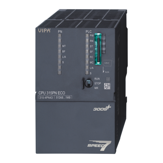
System 300S Hardware description Structure > Interfaces 4.2 Structure 4.2.1 General CPU 315-4PN43 Storage media slot (lockable) LED status indication CPU part LED status indication PROFINET IO controller Operating mode switch CPU X5: Ethernet PG/OP channel X1: Slot for DC 24V power supply X2: MPI interface X3: PtP interface X8: PROFINET IO controller... -
Page 24: Memory Management
Hardware description System 300S Structure > Memory management X2: MPI interface 9pin SubD jack: The MPI interface serves for the connection between programming unit and CPU. By means of this the project engineering and programming happens. MPI serves for communication between several CPUs or between HMIs and CPU. Standard setting is MPI Address 2. -
Page 25: Slot For Storage Media
System 300S Hardware description Structure > LEDs 4.2.4 Slot for storage media At this slot the following storage media can be plugged: SD respectively MCC (Multimedia card) – External memory card for programs and firmware. MCC - Memory configuration card –... - Page 26 Hardware description System 300S Structure > LEDs Meaning (RUN) (STOP) (SFAIL) (FRCE) (MMC) green yellow yellow yellow Boot-up after PowerON - as soon as the CPU is supplied with 5V, the green PW-LED (Power) is on. Firmware is loaded. 10Hz Initialization: Phase 1 Initialization: Phase 2 Initialization: Phase 3...
- Page 27 System 300S Hardware description Structure > LEDs Ethernet PG/OP channel Meaning (Link/Activity) (Speed) green green The Ethernet PG/OP channel is physically connected to Ethernet. There is no physical connection. Shows Ethernet activity. flickers The Ethernet interface of the Ethernet PG/OP channel has a transfer rate of 100Mbit.
- Page 28 Hardware description System 300S Structure > LEDs LEDs PROFINET IO con- troller X8 MT (Maintenance) BF (Bus error) Meaning yellow Bus error, no connection to sub net/switch wrong transfer rate Full-duplex-transmission is not activated Failure of a connected IO device At least one IO device is not access-able Faulty configuration Maintenance event is pending.
-
Page 29: Technical Data
System 300S Hardware description Technical data 4.3 Technical data Order no. 315-4PN43 Type CPU 315PN ECO SPEED-Bus Technical data power supply Power supply (rated value) DC 24 V Power supply (permitted range) DC 20.4...28.8 V Reverse polarity protection ü Current consumption (no-load operation) 200 mA Current consumption (rated value) 0.7 A... - Page 30 Hardware description System 300S Technical data Order no. 315-4PN43 Supply voltage display green LED Group error display red SF LED Channel error display none Command processing times Bit instructions, min. 0.01 µs Word instruction, min. 0.01 µs Double integer arithmetic, min. 0.01 µs Floating-point arithmetic, min.
- Page 31 System 300S Hardware description Technical data Order no. 315-4PN43 Time Real-time clock buffered ü Clock buffered period (min.) Type of buffering Vanadium Rechargeable Lithium Battery Load time for 50% buffering period 20 h Load time for 100% buffering period 48 h Accuracy (max.
- Page 32 Hardware description System 300S Technical data Order no. 315-4PN43 S7 basic communication ü S7 basic communication, user data per job 76 Byte S7 communication ü S7 communication as server ü S7 communication as client S7 communication, user data per job 160 Byte Number of connections, max.
- Page 33 System 300S Hardware description Technical data Order no. 315-4PN43 S7 basic communication ü S7 communication ü S7 communication as server ü S7 communication as client Transmission speed, min. 19.2 kbit/s Transmission speed, max. 12 Mbit/s Functionality PROFIBUS master Number of connections, max. PG/OP channel Routing S7 basic communication...
- Page 34 Hardware description System 300S Technical data Order no. 315-4PN43 Transfer memory inputs, max. Transfer memory outputs, max. Address areas, max. User data per address area, max. Point-to-point communication PtP communication ü Interface isolated ü RS232 interface RS422 interface RS485 interface ü...
- Page 35 System 300S Hardware description Technical data Order no. 315-4PN43 Type Type of interface Ethernet 10/100 MBit Connector RJ45 Electrically isolated ü PG/OP channel ü Number of connections, max. Productive connections Fieldbus Type Type of interface Ethernet 10/100 MBit Connector RJ45 Electrically isolated ü...
- Page 36 Hardware description System 300S Technical data Order no. 315-4PN43 ISO on TCP connections (RFC 1006) TSEND, TRCV, TCON, TDISCON User data per ISO on TCP connection, max. 8 KB TCP-Connections native TSEND, TRCV, TCON, TDISCON User data per native TCP connection, max. 8 KB User data per ad hoc TCP connection, max.
-
Page 37: Deployment Cpu 315-4Pn43
System 300S Deployment CPU 315-4PN43 Start-up behavior Deployment CPU 315-4PN43 5.1 Assembly Ä Chap. 3 ‘Assembly and Information about assembly and cabling: installation guidelines’ page 16 5.2 Start-up behavior Turn on power supply After the power supply has been switched on, the CPU changes to the operating mode the operating mode lever shows. -
Page 38: Addressing
Deployment CPU 315-4PN43 System 300S Addressing > Addressing Backplane bus I/O devices 5.3 Addressing 5.3.1 Overview To provide specific addressing of the installed peripheral modules, certain addresses must be allocated in the CPU. At the start-up of the CPU, this assigns automatically peripheral addresses for digital in-/output modules starting with 0 and ascending depending on the slot location. - Page 39 System 300S Deployment CPU 315-4PN43 Addressing > Addressing Backplane bus I/O devices Example for automatic The following sample shows the functionality of the automatic address allocation: address allocation HB140 | CPU | 315-4PN43 | en | 18-02...
-
Page 40: Hardware Configuration - Cpu
Deployment CPU 315-4PN43 System 300S Hardware configuration - CPU 5.4 Hardware configuration - CPU Precondition The configuration of the CPU takes place at the Siemens ‘hardware configurator’ . The hardware configurator is part of the Siemens SIMATIC Manager. It serves for project engi- neering. -
Page 41: Hardware Configuration - I/O Modules
System 300S Deployment CPU 315-4PN43 Hardware configuration - I/O modules 5.5 Hardware configuration - I/O modules Hardware configuration of After the hardware configuration place the System 300 modules in the plugged sequence the modules starting with slot 4. Parametrization For parametrization double-click during the project engineering at the slot overview on the module you want to parameterize. -
Page 42: Hardware Configuration - Ethernet Pg/Op Channel
Deployment CPU 315-4PN43 System 300S Hardware configuration - Ethernet PG/OP channel 5.6 Hardware configuration - Ethernet PG/OP channel Overview The CPU 315-4PN43 has an integrated Ethernet PG/OP channel. This channel allows you to program and remote control your CPU. The PG/OP channel also gives you access to the internal web page that contains information about firmware version, connected I/O devices, current cycle times etc. -
Page 43: Hardware Configuration - Communication
System 300S Deployment CPU 315-4PN43 Setting standard CPU parameters > Parameterization via Siemens CPU Take IP address parame- Open the Siemens hardware configurator und configure the Siemens CPU 315-2 ters in project PN/DP (6ES7 315-2EH14-0AB0 V3.2). Configure the modules at the standard bus. For the Ethernet PG/OP channel you have to configure a Siemens CP 343-1 (SIMATIC 300 \ CP 300 \ Industrial Ethernet \CP 343-1 \ 6GK7 343-1EX11 0XE0) always below the really plugged modules. -
Page 44: Parameters Cpu
Deployment CPU 315-4PN43 System 300S Setting standard CPU parameters > Parameters CPU 5.8.2 Parameters CPU Supported parameters The CPU does not evaluate each parameter, which may be set at the hardware configu- ration. The following parameters are supported by the CPU at this time: General Short description –... - Page 45 – The Yaskawa CPU is preset such that OB 85 is not called if an I/O access error occurs and no entry is made in the diagnostic buffer either.
- Page 46 Deployment CPU 315-4PN43 System 300S Setting standard CPU parameters > Parameters CPU Execution – Select how often the interrupts are to be triggered. – Intervals ranging from every minute to yearly are available. The intervals apply to the settings made for start date and time. Start date/time –...
-
Page 47: Parameters For Mpi/Dp
System 300S Deployment CPU 315-4PN43 Setting VIPA specific CPU parameters > Proceeding Protection Level of protection – Here 1 of 3 protection levels may be set to protect the CPU from unauthorized access. – Protection level 1 (default setting): No password adjustable, no restrictions –... -
Page 48: Vipa Specific Parameters
Select ‘Options è Install new GSD-file’. Navigate to the directory VIPA_System_300S and select SPEEDBUS.GSD an. ð The SPEED7 CPUs and modules of the System 300S from Yaskawa may now be found in the hardware catalog at PROFIBUS-DP / Additional field devices / I/O / VIPA_SPEEDBUS. -
Page 49: Project Transfer
This means the same rules are valid and you use the same components for the build-up. The single participants are connected with each other via bus interface plugs and PROFIBUS cables. Per default the MPI net runs with 187.5kbaud. Yaskawa CPUs are delivered with MPI address 2. -
Page 50: Transfer Via Ethernet
Deployment CPU 315-4PN43 System 300S Project transfer > Transfer via Ethernet MPI programming cable Activate the terminating resistor via switch MPI network Proceeding transfer via Connect your PC to the MPI jack of your CPU via a MPI programming cable. MPI interface Load your project in the Siemens SIMATIC Manager. -
Page 51: Transfer Via Memory Card
System 300S Deployment CPU 315-4PN43 Accessing the web server With [OK] the transfer is started. System dependent you get a message that the projected system differs from target system. This message may be accepted by [OK]. ® Your project is transferred and may be executed in the CPU after transfer. - Page 52 Deployment CPU 315-4PN43 System 300S Accessing the web server Info - Overview Here order number, serial number and the version of firmware and hardware of the CPU are listed. [Expert View] takes you to the advanced "Expert View". Info - Expert View Runtime Information Operation Mode STOP...
- Page 53 WorkMemCode 0 / 524288 Bytes Load memory, working memory WorkMemData 0 / 524288 Bytes (code/data) PG/OP Network Information Device Name Yaskawa 315-4PN43 CPU Ethernet PG/OP channel: IP Address 172.16.129.210 Address information Subnet Mask 255.255.255.0 Gateway Address 172.16.129.210 MAC Address...
- Page 54 Deployment CPU 315-4PN43 System 300S Accessing the web server Info - Overview PROFINET-IO controller Info - Expert View Internal Information CPU component: 31x-PN Module Type 0xACDB0080 Information for support Module Firmware Information Bb000429 V1.1.0.12 AB000125 V0.1.0.3 PRODUCT VIPA 31x-PN V1.1.2.0 Px000300.pkg Hx000075 V1.1.0.0...
- Page 55 System 300S Deployment CPU 315-4PN43 Accessing the web server Hardware Last value Average of last 10 values Minimum load Maximum load Network IP address 172.16.129.210 Subnet mask 255.255.255.0 Gateway address 172.16.129.210 MAC address 00:20:D5:77:91:10 Link mode 100 Mbps - Full duplex EMAC statistics Frames Transmitted OK Single Collision Frame...
- Page 56 Deployment CPU 315-4PN43 System 300S Accessing the web server Data - Input data Offset Width Value (dec) Value (hex) Data - Output data Offset Width Value (dec) Value (hex) New Value (hex) HB140 | CPU | 315-4PN43 | en | 18-02...
-
Page 57: Operating Modes
System 300S Deployment CPU 315-4PN43 Operating modes > Overview 5.12 Operating modes 5.12.1 Overview The CPU can be in one of 4 operating modes: Operating mode STOP Operating mode START-UP Operating mode RUN Operating mode HOLD Certain conditions in the operating modes START-UP and RUN require a specific reaction from the system program. - Page 58 Deployment CPU 315-4PN43 System 300S Operating modes > Overview Set the breakpoint with ‘Debug è Set Breakpoint’. ð The according command line is marked with a circle. To activate the breakpoint click on ‘Debug è Breakpoints Active’. ð The circle is changed to a filled circle. Bring your CPU into RUN.
-
Page 59: Function Security
(parameterizable min. 1ms) that stop res. execute a RESET at the CPU in case of an error and set it into a defined STOP state. The Yaskawa CPUs are developed function secure and have the following system properties:... -
Page 60: Overall Reset
Deployment CPU 315-4PN43 System 300S Overall reset 5.13 Overall reset Overview During the overall reset the entire user memory is erased. Data located in the memory card is not affected. If you have assigned IP address data to your PROFINET IO con- troller, these remain until there is a new PowerON. -
Page 61: Firmware Update
LEDs and the firmware may be installed by an update request. Latest firmware at The latest firmware versions are to be found in the service area at www.yaskawa.eu.com. www.yaskawa.eu.com For example the following files are necessary for the firmware update of the CPU 315-4PN43 and its components with hardware release 01: 315-4PN43, Hardware release 01: Px000309.pkg... - Page 62 Deployment CPU 315-4PN43 System 300S Firmware update Navigate via ‘System 300S è CPU 300S Plus’ to your CPU and download the zip file to your PC. Extract the zip file and copy the extracted pkg files to your memory card. CAUTION! With a firmware update an overall reset is automatically executed.
-
Page 63: Reset To Factory Settings
System 300S Deployment CPU 315-4PN43 Reset to factory settings 5.15 Reset to factory settings Proceeding With the following proceeding the internal RAM of the CPU is completely deleted and the CPU is reset to delivery state. Please regard that the MPI address is also reset to default 2 and the IP address of the Ethernet PG/OP channel is reset to 0.0.0.0! Ä... -
Page 64: Deployment Storage Media - Mmc, Mcc
You can cause the CPU to load a project automatically respectively to execute a com- mand file by means of pre-defined file names. The MMCs of Yaskawa are pre-formatted with the PC format FAT and can be accessed via a card reader. - Page 65 System 300S Deployment CPU 315-4PN43 Deployment storage media - MMC, MCC You may use the MCC also as "normal" MMC for storing your project. If the memory expansion on the MCC exceeds the maximum extendible memory range of the CPU, the maximum possible memory of the CPU is automatically used. You may determine the recent memory extension and the remaining time after pulling the MCC via the integrated web page.
-
Page 66: Extended Know-How Protection
System 300S Extended know-how protection 5.17 Extended know-how protection Overview Besides the "standard" Know-how protection the SPEED7 CPUs from Yaskawa provide an "extended" know-how protection that serves a secure block protection for accesses of 3. persons. Standard protection – The standard protection from Siemens transfers also protected blocks to the PG but their content is not displayed. -
Page 67: Cmd - Auto Commands
System 300S Deployment CPU 315-4PN43 CMD - auto commands 5.18 CMD - auto commands Overview A command file at a memory card is automatically executed under the following condi- tions: CPU is in STOP and memory card is stuck After each PowerON Command file The command file is a text file, which consists of a command sequence to be stored as vipa_cmd.mmc in the root directory of the memory card. -
Page 68: Diagnostic Entries
Accessing diagnostic data You may read the diagnostics buffer of the CPU via the Siemens SIMATIC Manager. Besides of the standard entries in the diagnostics buffer, the Yaskawa CPUs support some additional specific entries as Event-IDs. To monitor the diagnostics entries you choose in the Siemens SIMATIC manager ‘PLC è... -
Page 69: Control And Monitoring Of Variables With Test Functions
System 300S Deployment CPU 315-4PN43 Control and monitoring of variables with test functions 5.20 Control and monitoring of variables with test functions Overview For troubleshooting purposes and to display the status of certain variables you can access certain test functions via the menu item Debug of the Siemens SIMATIC Man- ager. - Page 70 Deployment CPU 315-4PN43 System 300S Control and monitoring of variables with test functions ‘PLC This test function returns the condition of a selected operand (inputs, outputs, flags, data è Monitor/Modify word, counters or timers) at the end of program execution. This information is obtained Variables’...
-
Page 71: Deployment Ptp Communication
RS485 parameterize FC/SFC 217 SER_SND RS485 send FC/SFC 218 SER_RCV RS485 receive More information about the usage of these blocks may be found in the manual "SPEED7 Operation List" from Yaskawa. HB140 | CPU | 315-4PN43 | en | 18-02... -
Page 72: Principle Of The Data Transfer
Deployment PtP communication System 300S Principle of the data transfer 6.2 Principle of the data transfer RS485 PtP communication The data transfer is handled during runtime by using FC/SFCs. The principle of data transfer is the same for all protocols and is shortly illustrated in the following. Data, which are written into the according data channel by the CPU, is stored in a FIFO send buffer (first in first out) with a size of 2x1024byte and then put out via the interface. -
Page 73: Deployment Of Rs485 Interface For Ptp
System 300S Deployment PtP communication Deployment of RS485 interface for PtP 6.3 Deployment of RS485 interface for PtP Properties RS485 Logical states represented by voltage differences between the two cores of a twisted pair cable Serial bus connection in two-wire technology using half duplex mode Data communications up to a max. -
Page 74: Parametrization
Deployment PtP communication System 300S Communication > FC/SFC 217 - SER_SND - Send to PtP Connection RS485 interface Periphery *) For traffic-free data transfer use a terminating resistor of approximately 6.4 Parametrization 6.4.1 FC/SFC 216 - SER_CFG - Parametrization PtP The parametrization happens during runtime deploying the FC/SFC 216 (SER_CFG). -
Page 75: Fc/Sfc 218 - Ser_Rcv - Receive From Ptp
SER_SND with the protocols USS and Modbus the acknowledgement telegram can be read. More information about the usage of these blocks may be found in the manual "SPEED7 Operation List" from Yaskawa. 6.6 Protocols and procedures Overview The CPU supports the following protocols and procedures:... - Page 76 Deployment PtP communication System 300S Protocols and procedures 3964 The 3964R procedure controls the data transfer of a point-to-point link between the CPU and a communication partner. The procedure adds control characters to the message data during data transfer. These control characters may be used by the communication partner to verify the complete and error free receipt.
- Page 77 System 300S Deployment PtP communication Protocols and procedures It is essential: You may connect 1 master and max. 31 slaves at the bus The single slaves are addressed by the master via an address sign in the telegram. The communication happens exclusively in half-duplex operation. After a send command, the acknowledgement telegram must be read by a call of the FC/SFC 218 SER_RCV.
- Page 78 Deployment PtP communication System 300S Protocols and procedures After a send command, the acknowledgement telegram must be read by a call of the FC/SFC 218 SER_RCV. The request telegrams send by the master and the respond telegrams of a slave have the following structure: Telegram structure Start sign...
-
Page 79: Modbus - Function Codes
Normally the access at Modbus happens by means of the ranges 0x, 1x, 3x and 4x. 0x and 1x gives you access to digital bit areas and 3x and 4x to analog word areas. For the CPs from Yaskawa is not differentiating digital and analog data, the following assignment is valid:... - Page 80 Deployment PtP communication System 300S Modbus - Function codes Code Command Description Read n bits Read n bits of master output area 0x Read n bits Read n bits of master input area 1x Read n words Read n words of master output area 4x Read n words Read n words master input area 3x Write 1 bit...
- Page 81 System 300S Deployment PtP communication Modbus - Function codes Command telegram Slave address Function code Address 1. bit Number of bits Check sum CRC/LRC 1byte 1byte 1word 1word 1word Respond telegram Slave address Function code Number of Data 1. byte Data 2.
- Page 82 Deployment PtP communication System 300S Modbus - Function codes Write 1 word 06h Code 06h: Write 1 word to master output area 4x Command telegram Slave address Function code Address word Value word Check sum CRC/LRC 1byte 1byte 1word 1word 1word Respond telegram Slave address...
-
Page 83: Modbus - Example Communication
System 300S Deployment PtP communication Modbus - Example communication 6.8 Modbus - Example communication Overview The example establishes a communication between a master and a slave via Modbus. The following combination options are shown: CPU 31xS as Modbus RTU master CPU 21xSER-1 as Modbus RTU slave Siemens SIMATIC Manager and possibilities for the project transfer Modbus cable connection... - Page 84 Deployment PtP communication System 300S Modbus - Example communication HB140 | CPU | 315-4PN43 | en | 18-02...
-
Page 85: Deployment Ethernet Communication - Productive
System 300S Deployment Ethernet communication - productive Basics - Industrial Ethernet in automation Deployment Ethernet communication - productive 7.1 Basics - Industrial Ethernet in automation Overview The flow of information in a company presents a vast spectrum of requirements that must be met by the communication systems. -
Page 86: Basics - Iso/Osi Reference Model
Deployment Ethernet communication - productive System 300S Basics - ISO/OSI reference model 7.2 Basics - ISO/OSI reference model Overview The ISO/OSI reference model is based on a proposal that was developed by the Interna- tional Standards Organization (ISO). This represents the first step towards an interna- tional standard for the different protocols. - Page 87 System 300S Deployment Ethernet communication - productive Basics - ISO/OSI reference model Layer 5 - Session layer The session layer is also called the communication control layer. It relieves the communi- cation between service deliverer and the requestor by establishing and holding the con- nection if the transport system has a short time fail out.
-
Page 88: Basics - Terms
Deployment Ethernet communication - productive System 300S Basics - Terms 7.3 Basics - Terms Network (LAN) A network res. LAN (Local Area Network) provides a link between different stations that enables them to communicate with each other. Network stations consist of PCs, IPCs, TCP/IP adapters, etc. -
Page 89: Basics - Protocols
The acknowledgement of the data transfer is established from the partner station at level 7 of the ISO/OSI reference model. At the PLC side FB/SFB Yaskawa handling blocks are necessary for data transfer for the Siemens S7 connections. More information about the usage of these blocks may be found in the manual "SPEED7 Operation List"... -
Page 90: Basics - Ip Address And Subnet
Deployment Ethernet communication - productive System 300S Basics - IP address and subnet Open communication In the ‘open communication’ the communication takes place via the user program by means of handling blocks. These blocks are also part of the Siemens SIMATIC Manager. You will find these in the ‘Standard Library’... - Page 91 System 300S Deployment Ethernet communication - productive Basics - IP address and subnet Subnet mask binary all "1" binary all "0" IPv4 address Net-ID Host-ID Subnet mask and IPv4 address Net-ID Subnet-ID new Host-ID Address at first start-up At the first start-up of the CPU, the Ethernet PG/OP channel and the PROFINET IO con- troller do not have an IP address.
-
Page 92: Fast Introduction
Deployment Ethernet communication - productive System 300S Commissioning and initialization Never choose an IP address with Host-ID=0 or Host-ID=maximum! (e.g. for class B with subnet mask = 255.255.0.0, the "172.16.0.0" is reserved and the "172.16.255.255" is occupied as local broadcast address for this network.) 7.6 Fast introduction Overview... -
Page 93: Hardware Configuration - Cpu
System 300S Deployment Ethernet communication - productive Hardware configuration - CPU Assign IP address param- You get valid IP address parameters from your system administrator. The assignment of eters the IP address data happens online in the Siemens SIMATIC Manager starting with ver- sion V 5.3 &... -
Page 94: Configure Siemens S7 Connections
"In unknown project" or via deputy objects like "Other stations" or Siemens "SIMATIC S5 Sta- tion". The communication is controlled by the user program with Yaskawa handling blocks. To use this blocks, configured communication connections are always necessary in the active station. - Page 95 System 300S Deployment Ethernet communication - productive Configure Siemens S7 connections Work environment of For the project engineering of connections, a thorough knowledge with NetPro from Sie- NetPro mens is required! The following passage only describes the basic usage of NetPro. More detailed information about NetPro is to be found in the according online manual res.
- Page 96 Deployment Ethernet communication - productive System 300S Configure Siemens S7 connections Projecting connections For the project engineering of connections, open the connection list by selecting the according CPU. Choose Insert new connection in the context menu: Connection partner (partner station) A dialog window opens where you may choose the connection partner and the connection type.
- Page 97 With this CPU exclusively Siemens S7 connection may be configured with Siemens NetPro. Siemens S7 connection For data transfer with Siemens S7 connections the FB/SFB Yaskawa handling blocks are necessary; the deployment is described in the manual "Operation list" of your CPU.
- Page 98 Communication functions communication functions: Siemens S7-300 communication functions: By integration of the function blocks FB 12 ... FB 15 from Yaskawa you may access the Siemens S7-300 communication functions. Siemens S7-400 communication functions: For the Siemens S7-400 communication functions the SFB 12 ... SFB 15 are to be used, which were integrated to the operating system of the CPU.
- Page 99 System 300S Deployment Ethernet communication - productive Configure Siemens S7 connections Function blocks FB/SFB Label Description FB/SFB 12 BSEND Sending data in blocks: FB/SFB 12 BSEND sends data to a remote partner FB/SFB of the type BRCV (FB/SFB 13). The data area to be transmitted is segmented. Each segment is sent individually to the partner.
-
Page 100: Configure Open Communication
Deployment Ethernet communication - productive System 300S Configure Open Communication 7.10 Configure Open Communication Connection-oriented pro- Connection-oriented protocols establish a (logical) connection to the communication tocols partner before data transmission is started. And if necessary they terminate the connection after the data transfer was finished. Connection-oriented protocols are used for data transmission when reliable, guaran- teed delivery is of particular importance. -
Page 101: Ncm Diagnostic - Help For Error Diagnostic
System 300S Deployment Ethernet communication - productive NCM diagnostic - Help for error diagnostic Handling blocks Those in the following listed UTDs and FBs serve for "open communication" with other Ethernet capable communication partners via your user program. These blocks are part of the Siemens SIMATIC Manager. - Page 102 Deployment Ethernet communication - productive System 300S NCM diagnostic - Help for error diagnostic Please always enter for the PROFINET IO controller as destination parameter 0 as module rack and 125 as slot. The CP can be reached exclusively with these settings. The following pages contain a short description of the NCM diagnostic.
- Page 103 Attachment...: Ind. Ethernet TCP/IP Node addr.: Enter the IP address of the CP Rack/slot: For the Yaskawa PROFINET IO controller please enter 0 for module rack and 125 as slot. Set your PG/PC interface to "TCP/IP -> Network card ..". Via [OK] you start the online diagnostic.
-
Page 104: Deployment Ethernet Communication - Profinet
Deployment Ethernet communication - PROFINET System 300S Basics PROFINET Deployment Ethernet communication - PROFINET 8.1 Basics PROFINET General PROFINET is an open Industrial Ethernet Standard from PROFIBUS & PROFINET International (PI) for automation. PROFINET is standardized in the IEC 61158. PROFINET uses TCP/IP and IT standards and supplements the PROFIBUS tech- nology for applications, where fast data communication with industrial IT functions is demanded. - Page 105 With this additional addressing mode with using of different applications, the overlap- ping of data areas can be prevented. Currently PROFINET IO devices from Yaskawa support API 0. GSDML file From VIPA there is a GSDML files for your IO device available. This file may either be found on the supplied storage media or at the download area of www.vipa.com.
-
Page 106: Profinet Installation Guidelines
Deployment Ethernet communication - PROFINET System 300S PROFINET installation guidelines 8.2 PROFINET installation guidelines Generals to data security The topic of data security and access protection have become increasingly important in the industrial environment. The increased networking of entire industrial systems to the network levels within the company together with the functions of remote mainte- nance have all served to increase vulnerability. -
Page 107: Profinet System Limits
System 300S Deployment Ethernet communication - PROFINET PROFINET system limits Tree If you interconnect several star structures, you obtain a tree network topology. Example network 8.3 PROFINET system limits Maximum number devices Based on the devices, which have to communicate with the IO controller per ms, you can and configurable connec- determine the maximum number of devices. - Page 108 Deployment Ethernet communication - PROFINET System 300S PROFINET system limits The PROFINET IO controller has the following system limits: Max. Number output bytes per ms: 800 Max. Number output bytes per device: 256 Input bytes per ms Input bytes per ms Number of devices C Number input bytes per device A Refresh time per device...
-
Page 109: Fast Introduction
System 300S Deployment Ethernet communication - PROFINET Fast introduction 8.4 Fast introduction Overview Range of functions Please regard that the PROFINET IO controller supports only the PROFINET functions, which are described in this manual, even if the Sie- mens CPU, which is used for configuration, offers further functions! To use some described PROFINET functions, it is necessary to deploy another Siemens CPU for configuration. -
Page 110: Commissioning And Initialization
Deployment Ethernet communication - PROFINET System 300S Commissioning and Initialization 8.5 Commissioning and Initialization Assembly and commis- Install your System 300S with your CPU. sioning Wire the system by connecting cables for voltage supply and signals Connect your PROFINET IO controller with Ethernet. Switch on the power supply. -
Page 111: Hardware Configuration - Cpu
System 300S Deployment Ethernet communication - PROFINET Hardware configuration - CPU 8.6 Hardware configuration - CPU Precondition The configuration of the CPU takes place at the Siemens ‘hardware configurator’ . The hardware configurator is part of the Siemens SIMATIC Manager. It serves for project engi- neering. -
Page 112: Parameters - Profinet Io Controller
Deployment Ethernet communication - PROFINET System 300S Parameters - PROFINET IO controller > PN-IO 8.7 Parameters - PROFINET IO controller 8.7.1 Precondition To parametrize the PROFINET IO controller of the CPU, the following conditions must be fulfilled: The PROFINET IO controller is online reachable, this means an initialization was established. -
Page 113: Port 1
System 300S Deployment Ethernet communication - PROFINET Parameters - PROFINET IO controller > Port 1 Synchronization This tab shows the synchronization properties of the IO controller. Here nothing can be changed. Time-of-day synchroniza- Here you can configure time-of-day master for time-of-day synchronization in the network. tion NTP (Network Time Protocol) is used to implement a TCP/IP protocol for time-of-day syn- chronization in networks. -
Page 114: Configuration Profinet Io Device
The modules, which may be configured here are listed in the hardware catalog. For the deployment of the PROFINET IO devices from Yaskawa you have to include the modules into the hardware catalog by means of the GSDML file from VIPA. -
Page 115: Configuration Profinet-I-Device / Shared-Device
System 300S Deployment Ethernet communication - PROFINET Configuration PROFINET-I-Device / Shared-Device 8.9 Configuration PROFINET-I-Device / Shared-Device General I-Device (Intelligent device) offers PROFINET I/O communication of a CPU with I/O periphery as "intelligent device" to a higher-lever CPU. Here the communication hap- pens by means of an I/O area, which was defined in the I-Device, before. -
Page 116: Topology - Configuration
Deployment Ethernet communication - PROFINET System 300S Topology - Configuration 8.10 Topology - Configuration Overview By configuring the topology you specify for the PROFINET IO controller the physical con- nections between the stations in your PROFINET IO system These "neighbourhood rela- tions"... -
Page 117: Device Replacement Without Exchangeable Medium/Pg
System 300S Deployment Ethernet communication - PROFINET Device replacement without exchangeable medium/PG 8.11 Device replacement without exchangeable medium/PG Please consider that for this function the Siemens CPU 315-2 PN/DP (6ES7 315-2EH14-0AB0 V3.2) is to be used of the hardware catalog. For this the Siemens SIMATIC Manager V 5.5, SP2 and up is to be used. -
Page 118: Replace Device
Deployment Ethernet communication - PROFINET System 300S Device replacement without exchangeable medium/PG > Replace device 8.11.1 Replace device Prepare the replace device For the replacement the "replace device" must be in "delivery state". If you have not received a new "replace device" from VIPA, you have to prepare this with the following approach: For this connect your "replace device"... -
Page 119: Commissioning And Start-Up Behaviour
System 300S Deployment Ethernet communication - PROFINET Commissioning and start-up behaviour 8.12 Commissioning and start-up behaviour Start-up on delivery In the delivery state the CPU is overall reset. The PROFINET part is deactivated and its LEDs are off after PowerON. Online with bus parame- For the communication between IO controller and IO device the ways for the commu- ters without project... -
Page 120: Profinet Diagnostics
Deployment Ethernet communication - PROFINET System 300S PROFINET diagnostics > Diagnostics during runtime in the user program 8.13 PROFINET diagnostics 8.13.1 Overview There are the following possibilities to get diagnostics information from your system: Diagnostics with the configuration and engineering tool Diagnostics during runtime in the user program (OB 1, SFB 52) Diagnostics via OB start information Diagnostics via status LEDs... - Page 121 System 300S Deployment Ethernet communication - PROFINET PROFINET diagnostics > Diagnostics during runtime in the user program Example OB1 For the cyclic access to the diagnostics data of the system SLIO module 050-1BA00 the following example may be used in the OB 1: AN M10.3 'If the reading terminated (BUSY=0) and AN M10.1 'there is no job triggered (REQ=0) then M10.1 'start transfer of record (REQ:=1)
-
Page 122: Diagnostics Via Ob Start Information
Deployment Ethernet communication - PROFINET System 300S PROFINET diagnostics > Diagnostics via OB start information 8.13.4 Diagnostics via OB start information On an error the faulty system generates a diagnostics message for the CPU. Then the CPU calls the according diagnostics OB. Here the CPU operating system trans- fers start information to the local data of the OB. -
Page 123: Diagnostics Via Status Leds
System 300S Deployment Ethernet communication - PROFINET PROFINET diagnostics > Diagnostics via status LEDs 8.13.5 Diagnostics via status LEDs LEDs PROFINET IO con- troller X8 MT (Maintenance) BF (Bus error) Meaning yellow Bus error, no connection to sub net/switch wrong transfer rate Full-duplex-transmission is not activated Failure of a connected IO device At least one IO device is not access-able... -
Page 124: Configuration With Tia Portal
9.1.1 General General In this chapter the project engineering of the Yaskawa CPU in the Siemens TIA Portal is shown. Here only the basic usage of the Siemens TIA Portal together with a Yaskawa CPU is shown. Please note that software changes can not always be considered and it may thus be deviations to the description. -
Page 125: Work Environment Of The Tia Portal
System 300S Configuration with TIA Portal TIA Portal - Work environment > Work environment of the TIA Portal 9.1.2 Work environment of the TIA Portal Basically, the TIA Portal has the following 2 views. With the button on the left below you can switch between these views: Portal view The ‘Portal view’... -
Page 126: Tia Portal - Hardware Configuration - Cpu
TIA Portal - Hardware configuration - CPU 9.2 TIA Portal - Hardware configuration - CPU Configuration Siemens With the Siemens TIA Portal the CPU from Yaskawa is to be configured as CPU 315-2 PN/DP (6ES7 315-2EH14-0AB0 V3.2) from Siemens. Start the Siemens TIA Portal. -
Page 127: Tia Portal - Hardware Configuration - I/O Modules
System 300S Configuration with TIA Portal TIA Portal - Hardware configuration - I/O modules 9.3 TIA Portal - Hardware configuration - I/O modules Hardware configuration of After the hardware configuration of the CPU place the System 300 modules at the bus in the modules the plugged sequence. -
Page 128: Tia Portal - Hardware Configuration - Ethernet Pg/Op Channel
Configuration with TIA Portal System 300S TIA Portal - Hardware configuration - Ethernet PG/OP channel 9.4 TIA Portal - Hardware configuration - Ethernet PG/OP channel Overview The CPU has an integrated Ethernet PG/OP channel. This channel allows you to pro- gram and remote control your CPU. - Page 129 System 300S Configuration with TIA Portal TIA Portal - Hardware configuration - Ethernet PG/OP channel Confirm with [Assign IP configuration]. ð Directly after the assignment the Ethernet PG/OP channel is online reachable using the set IP address data. The value remains as long as it is reassigned, it is overwritten by a hardware configuration or an factory reset is executed.
-
Page 130: Tia Portal - Hardware Configuration - Pg/Op Via Profinet
Configuration with TIA Portal System 300S TIA Portal - Hardware configuration - PG/OP via PROFINET Device overview: Module Slot Type PLC... CPU ... DI... DI... DO... DO... DIO... DIO... AI... AI... AO... AO... CP 343-1 CP 343-1 9.5 TIA Portal - Hardware configuration - PG/OP via PROFINET Overview The CPU has an Ethernet interface X8 integrated for PROFINET. - Page 131 System 300S Configuration with TIA Portal TIA Portal - Hardware configuration - PG/OP via PROFINET Assign IP address param- You get valid IP address parameters from your system administrator. The assignment of eters the IP address data happens online in the Siemens TIA Portal with the following pro- ceeding: Start the Siemens TIA Portal.
-
Page 132: Tia Portal - Setting Vipa Specific Cpu Parameters
Configuration with TIA Portal System 300S TIA Portal - Setting VIPA specific CPU parameters Take IP address parame- Open your project. ters in project If not already done, configure in the ‘Device configuration’ a Siemens CPU 315-2 PN/DP (6ES7 315-2EH14-0AB0 V3.2). Open the "Property"... - Page 133 Select ‘Options è Install new GSD-file’. Navigate to the directory VIPA_System_300S and select SPEEDBUS.GSD an. ð The SPEED7 CPUs and modules of the System 300S from Yaskawa may now be found in the hardware catalog at PROFIBUS-DP / Additional field devices / I/O / VIPA_SPEEDBUS.
- Page 134 Configuration with TIA Portal System 300S TIA Portal - Setting VIPA specific CPU parameters Device overview Module Slot Type PLC... CPU ... DI... DI... DO... DO... DIO... DIO... AI... AI... AO... AO... CP 343-1 CP 343-1 CP 342-5 CP 342-5 Thus, the VIPA components can be displayed, you have to deactivate the "Filter"...
- Page 135 System 300S Configuration with TIA Portal TIA Portal - Setting VIPA specific CPU parameters Click at the slave system and open the ‘Device overview’ in the Project area. Configure at slot 1 the VIPA CPU 315-4PN43 of the hardware catalog from VIPA_SPEEDbus.
-
Page 136: Tia Portal - Yaskawa-Include Library
Downloads > VIPA LIB. The library is available as packed zip file for the corresponding TIA Portal version. As soon as you want to use Yaskawa specific blocks you have to import them into your project. -
Page 137: Tia Portal - Project Transfer
System 300S Configuration with TIA Portal TIA Portal - Project transfer 9.8 TIA Portal - Project transfer Overview There are the following possibilities for project transfer into the CPU: Transfer via MPI Transfer via Ethernet Transfer via memory card Transfer via MPI Currently the VIPA programming cables for transfer via MPI are not supported. - Page 138 Configuration with TIA Portal System 300S TIA Portal - Project transfer Transfer via memory card The memory card serves as external storage medium. There may be stored several proj- ects and sub-directories on a memory card. Please regard that your current project is stored in the root directory and has one of the following file names: S7PROG.WLD AUTOLOAD.WLD...
-
Page 139: Appendix
System 300S Appendix Appendix HB140 | CPU | 315-4PN43 | en | 18-02... - Page 140 Appendix System 300S Content System specific event IDs................141 Integrated blocks.................... 189 SSL partial list....................193 HB140 | CPU | 315-4PN43 | en | 18-02...
-
Page 141: A System Specific Event Ids
System 300S System specific event IDs System specific event IDs Ä Chap. 5.19 ‘Diagnostic entries’ page 68 Event IDs Event ID Description 0x115C Manufacture interrupt for EtherCAT / PROFINET IO OB: OB number ZINFO1: Logical address of the slave station that triggered the interrupt ZINFO2: Interrupt type 0: Reserved 1: Diagnostic interrupt (incoming) - Page 142 System specific event IDs System 300S Event ID Description 0xE005 Internal error - Please contact the hotline! ZINFO1: Not user relevant ZINFO2: Not user relevant ZINFO3: Not user relevant 0xE007 Configured input/output bytes do not fit in the periphery area 0xE008 Internal error - Please contact the hotline! 0xE009...
- Page 143 System 300S System specific event IDs Event ID Description ZINFO1: Error 4: SSL wrong 5: Sub-SSL wrong 6: Index wrong ZINFO2: SZL-ID ZINFO3: Index 0xE0CC Communication error ZINFO1: Error code 1: Wrong priority 2: Buffer overrun 3: Telegram format error 4: Wrong SSL request (SSL-ID invalid) 5: Wrong SSL request (SSL-Sub-ID invalid) 6: Wrong SSL request (SSL-Index invalid)
- Page 144 System specific event IDs System 300S Event ID Description 0xE200 Memory card writing finished (Copy Ram2Rom) OB: Not user relevant PK: Not user relevant 0xE210 Memory card reading finished (reload after memory reset) OB: Not user relevant PK: Not user relevant ZINFO1 - Position 0: Not user relevant 0xE21D Memory card reading: Error on reload (after memory reset), error in the block header...
- Page 145 System 300S System specific event IDs Event ID Description 70: SFB 97: VDB 98: VSDB 99: VFC 100: VSFC 101: VFB 102: VSFB 111: VOB ZINFO3: Block number 0xE300 Internal flash writing completed (copy Ram2Rom) 0xE310 Internal flash reading completed (recharging after battery failure) 0xE400 FSC card was plugged OB: FSC activated from this slot (PK)
- Page 146 System specific event IDs System 300S Event ID Description 23357: 955-C000M00 24576: 955-C000050 35025: 955-C00MC10 36351: FSC-C000S40 36794: FSC-C000M40 37260: 955-C000S40 37833: 955-C000M40 38050: FSC-C00MC10 41460: 955-C000M50 41526: 955-C0PE040 42655: FSC-C00MC00 47852: 955-C00MC00 48709: FSC-C0PE040 50574: 955-C000M70 52366: 955-C000030 53501: FSC-C000030 58048: FSC-C000020 63411: 955-C000M60 65203: 955-C000020...
- Page 147 System 300S System specific event IDs Event ID Description 4940: FSC-C000S30 5755: 955-C0ME040 6843: FSC-C0NE040 8561: FSC-C000S20 9012: FSC-C000M20 13895: 955-C000060 15618: 955-C000S20 16199: 955-C000M20 17675: FSC-C000S00 18254: FSC-C000M00 20046: FSC-C000040 21053: 955-C000040 22904: 955-C000S00 23357: 955-C000M00 24576: 955-C000050 35025: 955-C00MC10 36351: FSC-C000S40 36794: FSC-C000M40 37260: 955-C000S40...
- Page 148 System specific event IDs System 300S Event ID Description ZINFO2: Number of released axes ZINFO3: Number of configured axes 0xE403 FSC can not be activated in this CPU OB: FCS error code PK: FSC source 0: CPU 1: Card ZINFO1: FSC(CRC) 1146: 955-C000070 1736: 955-C0NE040 2568: FSC-C0ME040...
- Page 149 System 300S System specific event IDs Event ID Description 47852: 955-C00MC00 48709: FSC-C0PE040 50574: 955-C000M70 52366: 955-C000030 53501: FSC-C000030 58048: FSC-C000020 63411: 955-C000M60 65203: 955-C000020 ZINFO2: FSC serial number (high word) ZINFO3: FSC serial number (low word) 0xE404 Feature set deleted due to CRC error 0xE405 The trial time of a feature set/memory card has expired OB: Action after the end of the trial time...
- Page 150 System specific event IDs System 300S Event ID Description 20046: FSC-C000040 21053: 955-C000040 22904: 955-C000S00 23357: 955-C000M00 24576: 955-C000050 35025: 955-C00MC10 36351: FSC-C000S40 36794: FSC-C000M40 37260: 955-C000S40 37833: 955-C000M40 38050: FSC-C00MC10 41460: 955-C000M50 41526: 955-C0PE040 42655: FSC-C00MC00 47852: 955-C00MC00 48709: FSC-C0PE040 50574: 955-C000M70 52366: 955-C000030 53501: FSC-C000030...
- Page 151 System 300S System specific event IDs Event ID Description 3903: 955-C000S30 4361: FSC-C000M30 4940: FSC-C000S30 5755: 955-C0ME040 6843: FSC-C0NE040 8561: FSC-C000S20 9012: FSC-C000M20 13895: 955-C000060 15618: 955-C000S20 16199: 955-C000M20 17675: FSC-C000S00 18254: FSC-C000M00 20046: FSC-C000040 21053: 955-C000040 22904: 955-C000S00 23357: 955-C000M00 24576: 955-C000050 35025: 955-C00MC10 36351: FSC-C000S40...
- Page 152 System specific event IDs System 300S Event ID Description 56: OB 65: DB 66: SDB 67: FC 68: SFC 69: FB 70: SFB 97: VDB 98: VSDB 99: VFC 100: VSFC 101: VFB 102: VSFB 111: VOB ZINFO3: Block number 0xE501 Parser error ZINFO1: Error code...
- Page 153 System 300S System specific event IDs Event ID Description 0xE503 Inconsistency of code sizes and block sizes in the working memory ZINFO1: Code size ZINFO2: Block size (high word) ZINFO3: Block size (low word) 0xE504 Additional information for CRC error in the working memory ZINFO2: Block address (high word) ZINFO3: Block address (low word) 0xE505...
- Page 154 System specific event IDs System 300S Event ID Description ZINFO3: Not user relevant DatID: Not user relevant 0xE705 Too many PROFIBUS slaves configured ZINFO1: Diagnostic address of the PROFIBUS master ZINFO2: Number of configured slaves ZINFO3: Number of admissible slaves 0xE710 On-board PROFIBUS/MPI: Bus error occurred PK: Not user relevant...
- Page 155 System 300S System specific event IDs Event ID Description ZINFO2: Length of the address range ZINFO3: Size of the process image DatID: Address range 0xE801 CMD - auto command: CMD_START recognized and executed 0xE802 CMD - auto command: CMD_End recognized and executed 0xE803 CMD - auto command: WAIT1SECOND recognized and executed 0xE804...
- Page 156 System specific event IDs System 300S Event ID Description 0xE80E CMD - auto command: SET_NETWORK recognized and executed 0xE80F Internal error - Please contact the hotline! ZINFO3: Status 0: OK 65153: File create error 65185: File writing error 65186: Odd address for reading 0xE810 Internal error - Please contact the hotline! 0xE811...
- Page 157 System 300S System specific event IDs Event ID Description 0xE901 Checksum error ZINFO1: Not user relevant ZINFO2: Not user relevant DatID: Not user relevant 0xE902 Internal error - Please contact the hotline! ZINFO1: Not user relevant ZINFO2: Not user relevant DatID: Not user relevant 0xE904 PG/OP: Multiple parametrization of a peripheral address...
- Page 158 System specific event IDs System 300S Event ID Description ZINFO1: Slot DatID: Not user relevant 0xEA02 SBUS: Internal error (internal plugged sub module not recognized) PK: Not user relevant ZINFO1: Slot ZINFO2: Type identifier target ZINFO3: Type identifier DatID: Not user relevant 0xEA03 SBUS: Communication error between CPU and IO controller OB: Operating mode...
- Page 159 System 300S System specific event IDs Event ID Description 7: Not Connected 8: Unknown DatID: Not user relevant 0xEA04 SBUS: Multiple configuration of a periphery address ZINFO1: Periphery address ZINFO2: Slot ZINFO3: Data width 0xEA05 Internal error - Please contact the hotline! 0xEA07 Internal error - Please contact the hotline! 0xEA08...
- Page 160 System specific event IDs System 300S Event ID Description PK: Not user relevant ZINFO2: HW slot ZINFO3: Interface type DatID: Not user relevant 0xEA1A SBUS: Error in access to SBUS FPGA address table PK: Not user relevant ZINFO2: HW slot ZINFO3: Table 0: Read 1: Writing...
- Page 161 System 300S System specific event IDs Event ID Description DatID: Line 0xEA50 PROFINET IO controller: Error in the configuration OB: Not user relevant PK: Not user relevant ZINFO1: Rack/slot of the controller ZINFO2: Device number ZINFO3: Slot at the device DatID: Not user relevant 0xEA51 PROFINET IO controller: There is no PROFINET IO controller at the configured slot...
- Page 162 System specific event IDs System 300S Event ID Description OB: File number PK: Slot of the controller ZINFO1: Firmware major version ZINFO2: Firmware minor version DatID: Line 0xEA62 Internal error - Please contact the hotline! OB: File number. PK: Slot of the controller ZINFO1: Firmware major version ZINFO2: Firmware minor version DatID: Line...
- Page 163 System 300S System specific event IDs Event ID Description ZINFO2 - Bit 2: DC parameter invalid ZINFO2 - Bit 3: I device configuration invalid (slot gap) ZINFO2 - Bit 4: MRP configuration invalid (client) 0xEA65 Internal error - Please contact the hotline! PK: Platform 0: none 8: CP...
- Page 164 System specific event IDs System 300S Event ID Description 1: Dataset error stack 2: Dataset error station ZINFO1: Dataset number ZINFO2: Dataset handle (caller) ZINFO3: Internal error code from PN stack DatID: Device 0xEA69 Internal error - Please contact the hotline! ZINFO1: Minimum version for the FPGA ZINFO2: Loaded FPGA version 0xEA6A...
- Page 165 System 300S System specific event IDs Event ID Description ZINFO2: Not user relevant ZINFO3: Not user relevant DatID: Not user relevant 0xEA6C PROFINET IO controller: Incorrect Device-ID OB: Operating mode 0: Configuration in operating condition RUN 1: STOP (update) 2: STOP (memory reset) 3: STOP (auto initialization) 4: STOP (internal) 5: STARTUP (cold start)
- Page 166 System specific event IDs System 300S Event ID Description 12: UPDATING 13: DEFECTIVE 14: Error search mode 15: De-energised 253: Process image release in STOP 254: Watchdog 255: Not set PK: Rack/slot ZINFO1: Device ID ZINFO2: Not user relevant ZINFO3: Not user relevant DatID: Not user relevant 0xEA6E PROFINET IO controller: Wait for RPC response...
- Page 167 System 300S System specific event IDs Event ID Description OB: Operating mode 0: Configuration in operating condition RUN 1: STOP (update) 2: STOP (memory reset) 3: STOP (auto initialization) 4: STOP (internal) 5: STARTUP (cold start) 6: STARTUP (restart/warm start) 7: STARTUP (hot restart) 9: RUN 10: HALT...
- Page 168 System specific event IDs System 300S Event ID Description 129: PNIO 207: RTA error 218: AlarmAck 219: IODConnectRes 220: IODReleaseRes 221: IOD/IOXControlRes 222: IODReadRes 223: IODWriteRes ZINFO2: ErrorDecode 128: PNIORW: Service Read Write 129: PNIO: Other Service or internal e.g. RPC errors 130: Vendor specific ZINFO3: Error code (PN spec.
- Page 169 System 300S System specific event IDs Event ID Description 0: INIT 1: STOP 2: READY 3: PAUSE 4: RUN ZINFO1: Filenamehash[0-3] ZINFO2: Filenamehash[4-7] ZINFO3: Line DatID: Current job number 0xEA92 Internal error - Please contact the hotline! OB: Current OB number PK: Core status 0: INIT 1: STOP...
- Page 170 System specific event IDs System 300S Event ID Description DatID: Not user relevant 0xEA99 Parameter assignment job could not be executed PK: Not user relevant ZINFO1: File version on MMC/SD (if not 0) ZINFO2: File version of the SBUS module (if not 0) ZINFO3: Slot DatID: Not user relevant 0xEAA0...
- Page 171 System 300S System specific event IDs Event ID Description 6: STARTUP (restart/warm start) 7: STARTUP (hot restart) 9: RUN 10: HALT 11: COUPLING 12: UPDATING 13: DEFECTIVE 14: Error search mode 15: De-energised 253: Process image release in STOP 254: Watchdog 255: Not set ZINFO1: Diagnostic address of the master ZINFO2: Current connection mode...
- Page 172 System specific event IDs System 300S Event ID Description PK: Not user relevant ZINFO1: Error type 1: SDB parser error 2: Configured address already used 3: Mapping error ZINFO2: Slot (0=cannot be determined) DatID: Not user relevant 0xEB04 SLIO-Bus: Multiple configuration of a periphery address ZINFO1: Periphery address ZINFO2: Slot DatID: Input...
- Page 173 System 300S System specific event IDs Event ID Description 3: Slot invalid 4: Master configuration invalid 5: Master type invalid 6: Slave diagnostic address invalid 7: Slave address invalid 8: Slave module IO configuration invalid 9: Logical address already in use 10: Internal error 11: IO mapping error 12: Error...
- Page 174 System specific event IDs System 300S Event ID Description 0xEC05 EtherCAT: Check the set DC mode of the YASKAWA Sigma 5/7 drive OB: Operating mode 0: Configuration in operating condition RUN 1: STOP (update) 2: STOP (memory reset) 3: STOP (auto initialization)
- Page 175 System 300S System specific event IDs Event ID Description 0: Undefined/Unkown 1: Init 2: PreOp 3: Bootstrap 4: SafeOp 8: Op ZINFO1 - Position 8: Previous status 0: Undefined/Unkown 1: Init 2: PreOp 3: Bootstrap 4: SafeOp 8: Op ZINFO2: Diagnostic address of the station ZINFO3: Number of stations, which are not in the same state as the master DatID: Station not available DatID: Station available...
- Page 176 System specific event IDs System 300S Event ID Description DatID: Input address DatID: Output address 0xEC12 EtherCAT: Recurrence slave ZINFO1 - Position 0: New status 0: Undefined/Unkown 1: Init 2: PreOp 3: Bootstrap 4: SafeOp 8: Op ZINFO1 - Position 8: Previous status 0: Undefined/Unkown 1: Init 2: PreOp...
- Page 177 System 300S System specific event IDs Event ID Description 10: HALT 11: COUPLING 12: UPDATING 13: DEFECTIVE 14: Error search mode 15: De-energised 253: Process image release in STOP 254: Watchdog 255: Not set ZINFO2: Diagnostic address of the master ZINFO3: DC state change 0: DC master out of sync 1: DC slave stations out of sync...
- Page 178 System specific event IDs System 300S Event ID Description DatID: Output address 0xED12 EtherCAT: Breakdown slave ZINFO1 - Position 0: New status 0: Undefined/Unkown 1: Init 2: PreOp 3: Bootstrap 4: SafeOp 8: Op ZINFO1 - Position 8: Previous status 0: Undefined/Unkown 1: Init 2: PreOp...
- Page 179 System 300S System specific event IDs Event ID Description 35: Slave station needs to be in SafeOp state 45: Invalid output FMMU configuration 46: Invalid input FMMU configuration 48: Invalid DC Sync configuration 49: Invalid DC Latch configuration 50: PLL error 51: Invalid DC IO error 52: Invalid DC time out error 66: Error in acyclic data exchange Ethernet Over EtherCAT...
- Page 180 System specific event IDs System 300S Event ID Description 0xED21 EtherCAT: Incorrect bus status change ZINFO1 - Position 0: New status 0: Undefined/Unkown 1: Init 2: PreOp 3: Bootstrap 4: SafeOp 8: Op ZINFO1 - Position 8: Previous status 0: Undefined/Unkown 1: Init 2: PreOp 3: Bootstrap...
- Page 181 System 300S System specific event IDs Event ID Description 3: Bootstrap 4: SafeOp 8: Op ZINFO2: Diagnostic address of the station ZINFO3: AlStatusCode 0: No error 1: Unspecified error 17: Invalid requested status change 18: Unknown requested status 19: Bootstrap not supported 20: No valid firmware 22: Invalid mailbox configuration 22: Invalid mailbox configuration...
- Page 182 System specific event IDs System 300S Event ID Description DatID: Station not available DatID: Station available DatID: Input address DatID: Output address 0xED23 EtherCAT: Time out while changing the master state to OP, after CPU has changed to RUN OB: Operating mode 0: Configuration in operating condition RUN 1: STOP (update) 2: STOP (memory reset)
- Page 183 System 300S System specific event IDs Event ID Description ZINFO2: Diagnostic address of the master 0xED31 EtherCAT: Overflow of the interrupt queue ZINFO2: Diagnostic address of the master 0xED40 Bus cycle time infringement occurred ZINFO1: Logical address of the IO system 0xED50 EtherCAT: Distributed clocks (DC) in sync OB: Operating mode...
- Page 184 System specific event IDs System 300S Event ID Description 7: STARTUP (hot restart) 9: RUN 10: HALT 11: COUPLING 12: UPDATING 13: DEFECTIVE 14: Error search mode 15: De-energised 253: Process image release in STOP 254: Watchdog 255: Not set ZINFO1 - Position 0: New status 0: Undefined/Unkown 1: Init...
- Page 185 System 300S System specific event IDs Event ID Description 33: Slave station needs to be in INIT state 34: Slave station needs to be in PreOp state 35: Slave station needs to be in SafeOp state 45: Invalid output FMMU configuration 46: Invalid input FMMU configuration 48: Invalid DC Sync configuration 49: Invalid DC Latch configuration...
- Page 186 System specific event IDs System 300S Event ID Description 0xED63 EtherCAT: Diagnostic buffer CP: Error in the response to an INIT command OB: EtherCAT station address (high byte) PK: EtherCAT station address (low byte) ZINFO1: Error type 0: Not defined 1: No response 2: Validation error 3: INIT command failed, requested station could not be reached...
- Page 187 System 300S System specific event IDs Event ID Description ZINFO2: Not user relevant ZINFO3: Not user relevant DatID: Not user relevant 0xEE01 Internal error - Please contact the hotline! ZINFO3: SFB number 0xEEEE CPU was completely deleted, since after PowerON the start-up could not be finished 0xEF00 Internal error - Please contact the hotline! DatID: Not user relevant...
- Page 188 System specific event IDs System 300S Event ID Description 29: The component actively disconnected the system connection to the CPU 31: Inconsistency of the component data base by loading SDB xxxx by the rack component (SDB type 0x3100) 32: Periphery enabled by S7-CPU 33: Periphery disabled by S7-CPU 34: Component STOP due to switch actuation 35: Component STOP due to invalid configuration...
-
Page 189: B Integrated Blocks
System 300S Integrated blocks Integrated blocks More information about this may be found in the manual "SPEED7 Oper- ation List" from Yaskawa. Name Description OB 1 CYCL_EXC Program Cycle OB 10 TOD_INT0 Time-of-day Interrupt OB 20 DEL_INT0 Time delay interrupt... - Page 190 Integrated blocks System 300S Name Description SFB 5 Create turn-off delay SFB 7 TIMEMESS Time measurement SFB 12 BSEND Sending data in blocks SFB 13 BRCV Receiving data in blocks: SFB 14 Remote CPU read SFB 15 Remote CPU write SFB 31 NOTIFY8P Messages without acknowledge display (8x)
- Page 191 System 300S Integrated blocks Name Description SFC 22 CREAT_DB Create a data block SFC 23 DEL_DB Deleting a data block SFC 24 TEST_DB Test data block SFC 25 COMPRESS Compressing the User Memory SFC 28 SET_TINT Set time-of-day interrupt SFC 29 CAN_TINT Cancel time-of-day interrupt SFC 30...
- Page 192 Integrated blocks System 300S Name Description SFC 68 X_PUT Write data SFC 69 X_ABORT Disconnect SFC 70 GEO_LOG Determining the start address of a module SFC 71 LOG_GEO Determining the slot belonging to a logical address SFC 75 SET_ADDR Set PROFIBUS MAC address SFC 81 UBLKMOV Copy data area without gaps...
-
Page 193: Cssl Partial List
System 300S SSL partial list SSL partial list More information about this may be found in the manual "SPEED7 Oper- ation List" from Yaskawa. SSL-ID SSL partial list xy11h Module identification xy12h CPU characteristics xy13h User memory areas xy14h System areas...
Need help?
Do you have a question about the System 300S+ CPU 315-4PN43 and is the answer not in the manual?
Questions and answers