Table of Contents

Related Manuals for Zepro ZHD 1500


Summary of Contents for Zepro ZHD 1500
- Page 1 74584TL USER MANUAL Operator & safety instructions Inspection & maintenance instructions USER MANUAL IN ORIGINAL This manual must be kept in the glove compartment in the truck at which the tail lift is installed 2018-01-03 www.zepro.com...
-
Page 3: Table Of Contents
Adjusting the platform to the dock ..........41 Maximum tilt down angle ............41 Using the platform as a ramp for forklifts and heavy pallet jacks ...............42 If you have damaged your ZEPRO tail lift ........42 The CONCEALED overload ............43 Table of Contents Continued on next page! - Page 4 Table of contents Service and maintenace..............44 Think of the lift! ................44 Safety information ..............45 General information service ............45 Daily safety device check list ............46 Once a week control of wear parts ..........46 Lubrication ..................47 Hydraulic oil / Hydraulic cleanliness ...........49 Service protocol L-Service Year 1 ..........50 Service protocol L-Service Year 2 ..........52 Service protocol XL-Service Year 3 ..........54...
-
Page 5: Value Document
Value document Value document The user manual must always be kept in the vehicle: • in order to check validity at CE marking • in order to prove possible warranty. • in order to overview service and changes through the years. If the number of pages for check and action taken isn’t enough, copies can be made for addition to this manual. -
Page 6: Product Approval
Product approval Declaration of conformity, manufacturer ORIGINAL (according to 2006/42 / EC, Annex 2A) ZEPRO, Z-Lyften Produktion AB Allévägen 4, 844 41 Bispgården SWEDEN hereby declares that the tail lift Type: Place for sticker Serial no: Complies with all applicable provisions of:... -
Page 7: Declaration Of Conformity, Installation
When Zepros installation instructions has been followed and possible modifications is approved by Zepro, this document is a confirmation that both the tail lift and installation confirms to the following directive. Machinery Directive 2006 / 42 / EC The installer certifies that: - installation has been carried out according to Zepros instructions. -
Page 9: Post Installation Checks
Product approval Post installation checks The following checks should be made to ensure that the tail lift has been correctly and safely installed. These checks should be carried out by the installer after the tail lift and vehicle have been prepared by him for regular operation. Checks (2, 3, 4, 5, 9, 11 och 15 if available). - Page 10 Product approval Post installation checks Oil leakage at hydraulic hoses, couplings and hydraulic units. Oil level, see instructions at hydraulic unit. Ground connection between tail lift and vehicle frame. See also manufacturers electric instructions. Function of control unit heating ele- ment.
- Page 11 Product approval Post installation checks Under run bar. Tightness and moun- ting position with regard to statutory measures. Tightness at all bolts at the tail lift. Greasing (see page 46). Load testing the tail lift (see instruction in installation instruction). Test of safety functions and possible accessory (see instruction in installation instruction).
-
Page 12: Possible Notes And Action Taken Post Installation Check
Product approval Possible notes and action taken Post installation check Action taken... -
Page 13: Safety Instructions
Safety instructions General safety This manual contains useful information about your Zepro lift: Technical description of equipment and function of these, technical safeguard, safety instructions for operators, everything according to: En 1756-1: English standard: Vehicles - Safety requirements for tail lifts for mounting on wheeled vehicles. - Page 14 Despite the tail lift is equipped is in use. with a non-slip surface, precaution must be taken at locomotion. Zepro recommends to use non-slip footwear according to EN ISO 20345, 20346 NOTE! and 20347.
-
Page 15: Restricted Area Of Use
Safety instructions Restricted area of use A tail lift has the sole purpose of aiding the loading and unloading of vehicles, thus, preventing the operator from making unnecessary physical efforts. Under no circumstances must a tail lift be used to scoop objects or material up from the ground or drive objects in the ground using the platform or other parts of the tail lift as driving tools. -
Page 16: Working Area
Safety instructions Working area The control units are located in such a way, so they will give: • A good oversee over the working area and the surroundings. • A safe position in proportion to passing traffic. Dangerzone: The area in which the platform is moving. This area may under no circumstances set foot on when the tail lift is in use. -
Page 17: Warning And Information Signs
Safety instructions Warning and information signs Warning flag Working area Loading diagram Warning tape Operating instruction Danger of crushing (Optional) Function 3-button sprial cable, with deactivation button... -
Page 18: Technical Safety
Warning flags & warning light To mark ”platform out” there is warning flags and warning lights at platforms, Your ZEPRO tail lift is equipped with safety mounted as alerts the surroundings during devices to prevent accidents. the tail lifts movement. The flags have... -
Page 19: Hydraulic System Safety
Safety instructions Hydraulic system safety The hydraulic system at Zepro tail lifts works under high pressure (up to 200 bar) and shall be maintained continuously in order to function at a reliable and safe way. All hydraulic units are equipped with an overflow valve as prevents that the tail lift can be raised or tilted with an overload. - Page 20 Safety instructions User safety The spiral cable control unit (remote) can be used from inside the vehicle standing at least 300 mm from the floor-edge to prevent risk of foot injury. Always use fixed control units at opening and closing of the tail lift. In order to avoid crush damages at operators, this person must always pay attention to the positioning of the feet in order to avoid the danger zone between body and the platform.
-
Page 21: Loading Diagram
Safety instructions Loading diagram Example on how the load weight changes when the distance to the body floors edge increases. This tail lift has a maximum load capacity of 2000 kg when the centre of gravity is 1000 mm from the edge of the body floor. -
Page 22: Technical Specifications
49,19 Closing platform 67,18 53,92 Remote Diagnostics System Zepro shall at all times have the right to: • install, maintain and dismantle automated remote diagnostics system or similar sensor-based system (the “System”) in and from the Equipment • access, send, receive, collect, store and use any and all information and data... -
Page 23: Function, Operation
Function, operation Description function The ZEPRO-lift is electro hydraulically The hydraulic system is protected with a driven. An electric motor which gets its pressure regulator when lifting or tilting power from the truck’s ordinary battery up. Note! This regulator does not prevent drives a hydraulic pump which supplies oil overload at rest position or lowering. -
Page 24: Overview Components
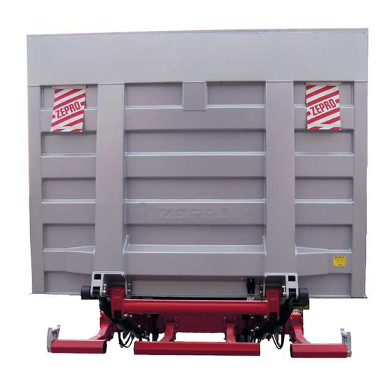
Function, operation Overview components PLATFORM MOUNTING BRACKET LIFT ARM SUPPORT FRAME TILT CYLINDER BUMPER BAR LIFT CYLINDER 3 PART BUMPER BAR... -
Page 25: Operating Standard Lift
Function, operation Operating standard lift WARNING The vehicle should be positioned so that operation of the tailgate lift can take place without danger from moving traffic... -
Page 26: Operating Standard Lift, 3 Buttons + Turn Switch
Function, operation Operating standard lift, 3 buttons + turn switch NOTE! Ensure that the tail lifts working area and periphery are clear. TILT DOWN TURN SWITCH Lower Activate the turn switch (4) and down (3) button in mentioned order. The FIXED CONTROL UNIT constant flow valve gives the same speed independent of the load. - Page 27 Function, operation Operating standard lift, 3 buttons + turn switch Tilt up Activate the turn switch (4) tilt button (2) NOTE! and up button (1) in mentioned order. The The platforms movement can platform tilts up. If the load is to heavy or stop at anytime (if the push placed to far back on the platform at tilt up, buttons are released) and in...
-
Page 28: Operating Slider, 5 Buttons
Function, operation Operating slider, 5 buttons NOTE! Ensure that the tail lifts working area and periphery are clear. TILT & WORK. P. INDICATOR DOWN SLIDER OUT SLIDER IN Function, fixed control unit Slider in Fold in the platform. Push red button (2) Slider out and button 5 (arrow right) at which the Push button 4 (arrow left) at which the tail... - Page 29 Function, operation Operating slider, 5 buttons Tilt down NOTE! Push tilt (2) and down button (3) in The platforms movement can mentioned order. Also here gives the stop at anytime (if the push constant flow valve the same speed buttons are released) and in independent of the load.
-
Page 30: Operating Standard Lift, 4 Buttons
Function, operation Operating standard lift, 4 buttons NOTE! Ensure that the tail lifts working area and periphery are clear. Lower Use button (3) and button (4). The constant flow valve gives the same speed independent of the load. 4-button control unit 4 button control is used to all operating of the tail lift in order to avoid crushing. - Page 31 Function, operation Operating standard lift, 4 buttons Automatic Tilt up from the ground Use buttons (1) and button (2). The NOTE! platform tilts up to horizontal level, then it The platforms movement can turns into normal lift function . If the load stop at anytime (if the push is to heavy or placed to far back on the buttons are released) and in...
-
Page 32: Operating Slider, 6 Buttons
Function, operation Operating slider, 6 buttons NOTE! Ensure that the tail lifts working area and periphery are clear. Function, control unit Slider out Push button 4 (arrow left) at which the tail lift slides out from transport position. Fold out the platform Automatic Tilt down to the ground Use button (2) and button (4). - Page 33 Function, operation Operating slider, 6 buttons Tilt up NOTE! Push button (1) and button (4). If the load The platforms movement can is to heavy or placed to far back on the stop at anytime (if the push platform at tilt up, the overflow valve opens. buttons are released) and in all positions because the push buttons break the current to...
-
Page 34: Operating, Slider Szf/Szft
Function, operation Operating, slider SZF/SZFT NOTE! Ensure that the tail lifts working area and periphery are clear. TILT & WORK. P. INDICATOR DOWN SLIDER OUT Function, fixed control unit SLIDER IN From working position: Lower Push down button (3). The platform lowers Lower to “slide out”... - Page 35 Function, operation Operating slider SZF/SZFT NOTE! Always lift up the platform Before loading/unloading against body floor before tilt Fold out the ramps. up/closing to transport position. NOTE! The platforms movement can stop at anytime (if the push buttons are released) and in After loading/unloading all positions because the push Fold in the ramps.
-
Page 36: Operating, Zr
Function, operation Operating, ZR NOTE! Ensure that the tail lifts working area and periphery are clear. TILT FIXED CONTROL UNIT DOWN Function, fixed control unit Lower to ”fold position” Lower Push down button (3). The folded platform Push down button (3). The platform lowers lowers. - Page 37 Function, operation Operating, ZR NOTE! Always lift up the platform against body floor before tilt up/closing to transport position. Tilt up Push tilt (2) and up (1) button in mentioned NOTE! order. The platform tilts up to horizontal The platforms movement can position.
-
Page 38: Operating, Foot Control Unit
Function, operation Operating, foot control unit NOTE! Ensure that the tail lifts working area and periphery are clear. 1 - ORANGE - UP 1 - BLACK - NEUTRAL 2 - GREEN - DOWN 2 - ORANGE - UP 3 - BLACK - NEUTRAL 3 - GREEN - DOWN Lower Lower... -
Page 39: Operating, Spiral Cable Control Unit
Function, operation Operating, spiral cable control unit Tilt down Push tilt (2) and down button (3) in mentioned order. The platform tilts NOTE! down against ground. Also here gives Opening and closing function is the constant flow valve the same speed only allowed with fixed control independent of the load. -
Page 40: Special Handling
Special handling Cargo transfer - truck to truck / truck to trailer When several tons heavy load is to be transferred from one truck to another, it means large overload, especially if the platforms are long. Maximum transfer weight = Taillift loading capacity x 0,5 Use the platform of the truck to be loaded as a ramp. -
Page 41: Adjusting The Platform To The Dock
Special handling Adjusting the platform to the dock Before you unload each article onto the dock use the control unit to tilt down. Make sure that the platform overlaps sufficiently (min 150 mm) and have a secure and solid resting position. -
Page 42: Using The Platform As A Ramp For Forklifts And Heavy Pallet Jacks
(min 150 mm) and have a secure and solid resting position. If you have damaged your ZEPRO tail lift If there has been an accident with the tail lift: Don’t hide or ”hush-up” any accident. It can be dangerous for you or somebody else. -
Page 43: The Concealed Overload
Special handling The CONCEALED overload You can’t overload the ZEPRO-lift when lifting or tilting up. The pressure relief valve will prevent it. At lowering or at ”resting platform” is however the overload unlimited. Unloading from dock with a forklift can be dangerous. -
Page 44: Service And Maintenace
For lubricating points, see the lubrication instruction IE-0101 NOTE! Hydraulic oil Check the oil level. Use Zepro oil or equivalent, if not available, please contact us. Change the oil once a year. Water and dirt can prevent the lift from working... -
Page 45: Safety Information
Break the circuit at the fuse. General information service Your ZEPRO lift has been designed to give you years of trouble-free service. Just like other mechanical devices it requires regular inspections and maintenance in order to ensure that it remains in optimum working order. -
Page 46: Daily Safety Device Check List
Service and maintenance Daily safety device check list Before use each day check that all safety devices are securely fixed and clearly visible eg. flags with reflector strips, warning decals, signs (Working area and loading diagram for all control units and platform). Check for damage to hoses. -
Page 47: Lubrication
Lubrication Which grease can I use? Zepro recommend an acid-free lithium-complex grease with a high quality paraffin base oil as ground. The grease must meet ASTM D 4950, SAE J310 and NLGI (grade 2) GC-LB specification as well be classed EP (extreme pressure). -
Page 49: Hydraulic Oil / Hydraulic Cleanliness
Neste Hydrauli Super 28 *Not a HF oil, as described below. * NOTE! ATF and HF oils should not be used unless permission from Zepro. HF oils can contain additives and these can have negative effect on polyurethane, that most of our cylinder sealing are made of. Also ATF oils can contain additives that affect plastic and rubber materials negatively. -
Page 50: Service Protocol L-Service Year 1
Service protocol L-Service Year 1 Service Protocol L-Service (annual) Customer: Vehicle: Reg.No: Lift model: Prod.No: C=Check R=Replace L=Lubrication * If the lift has the equipment See instructions for Service points Information Comments resp. lift models Mecanics (Visual inspection of any cracks and / or damage) IE-0110 IE-0105 / IE-0104 1.1 Mounting bracket... - Page 51 Note: If comment is marked for any of the service points; complete the task below Service control. (Mark the box for actions performed for each. service point.) Service- points Comments / Actions Inspection performed: Actions performed: Signature..........Signature..........Date......Date......Company stamp Company stamp 73014TL...
-
Page 52: Service Protocol L-Service Year 2
Service protocol L-Service Year 2 Service Protocol L-Service (annual) Customer: Vehicle: Reg.No: Lift model: Prod.No: C=Check R=Replace L=Lubrication * If the lift has the equipment See instructions for Service points Information Comments resp. lift models Mecanics (Visual inspection of any cracks and / or damage) IE-0110 IE-0105 / IE-0104 1.1 Mounting bracket... - Page 53 Note: If comment is marked for any of the service points; complete the task below Service control. (Mark the box for actions performed for each. service point.) Service- points Comments / Actions Inspection performed: Actions performed: Signature..........Signature..........Date......Date......Company stamp Company stamp 73014TL...
-
Page 54: Service Protocol Xl-Service Year 3
Service protocol XL-Service Year 3 Service Protocol XL-Service Incl. replacement of parts in Service Ki Customer: Vehicle: Reg.No: Lift model: Prod. No: C=Check R=Replace L=Lubrication * If the lift has the equipment **If the service kit contains the detail See instructions for Service points Information Comments... - Page 55 Note: If comment is marked for any of the service points; complete the task below Service control. (Mark the box for actions performed for each. service point.) Service- points Comments / Actions Inspection performed: Actions performed: Signature..........Signature..........Date......Date......Company stamp Company stamp 73020TL...
-
Page 56: Service Protocol L-Service (Annual) Year
Service protocol L-Service (Annual) Year..Service Protocol L-Service (annual) Customer: Vehicle: Reg.No: Lift model: Prod.No: C=Check R=Replace L=Lubrication * If the lift has the equipment See instructions for Service points Information Comments resp. lift models Mecanics (Visual inspection of any cracks and / or damage) IE-0110 IE-0105 / IE-0104 1.1 Mounting bracket... - Page 57 Note: If comment is marked for any of the service points; complete the task below Service control. (Mark the box for actions performed for each. service point.) Service- points Comments / Actions Inspection performed: Actions performed: Signature..........Signature..........Date......Date......Company stamp Company stamp 73014TL...
-
Page 58: Service Protocol Xl-Service (Every 3Rd Year) Year
Service protocol XL-Service (Every 3rd Year) Year..Service Protocol XL-Service Incl. replacement of parts in Service Ki Customer: Vehicle: Reg.No: Lift model: Prod. No: C=Check R=Replace L=Lubrication * If the lift has the equipment **If the service kit contains the detail See instructions for Service points Information... - Page 59 Note: If comment is marked for any of the service points; complete the task below Service control. (Mark the box for actions performed for each. service point.) Service- points Comments / Actions Inspection performed: Actions performed: Signature..........Signature..........Date......Date......Company stamp Company stamp 73020TL...
-
Page 60: Trouble Shooting
Trouble shooting Trouble shooting for operator For other faults, please contact service workshop Lifting Problem: Possible cause: Correction: Doesn’t lift, motor starts. The oil level is to low. Lower the platform to the ground, fill up oil to max level. Doesn’t lift, motor will not start Electrical fault Check fuses in truck cabin, taillift and... - Page 61 Trouble shooting Possible cause: Problem: Correction: Slow lowering Oil is to thick Change to Zepro oil or eqvivalent see page 47. The lifts bearings are Check that the lift arm and cylinders rough, ungreased or (piston rod) is undamaged. Lubricate damaged.
- Page 62 Check wiring / connections. Valves in hydraulic unit is activated Tilting down is slow Oil is to thick Change to Zepro oil or eqvivalent see page 21. The lifts bearings are Check that the lift arm and cylinders rough, ungreased or (piston rod) is undamaged.
- Page 63 Notes...
- Page 66 ZEPRO Sales / Importer Manufacturer Address: Telephone: Fax: KATRINEHOLM Mossvägen 8, 0150 - 489550 0150 - 489551 Sales S-641 49 Katrineholm, SWEDEN BISPGÅRDEN Allévägen 4, 0696 - 17200 0696 - 17244 Factory S-841 41 Bispgården, SWEDEN www.zepro.se www.zepro.com...
Need help?
Do you have a question about the ZHD 1500 and is the answer not in the manual?
Questions and answers