Advertisement
Quick Links
®
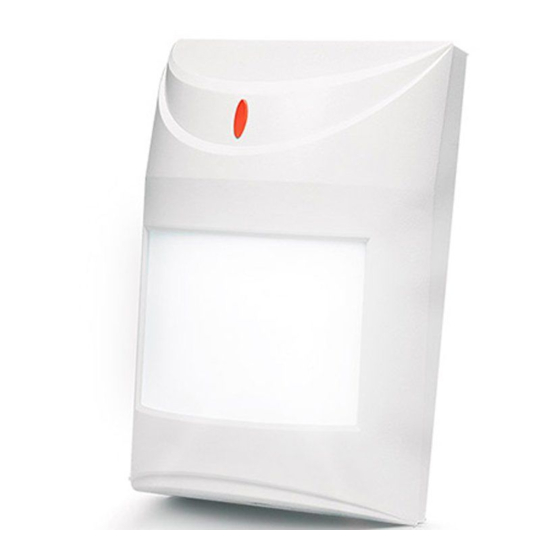
AQUA LUNA
DIGITAL PASSIVE INFRARED DETECTOR
WITH BACKLIGHT FEATURE
The microprocessor-based, fully digital AQUA LUNA detector is characterized by
high sensitivity and interference resistance. Due to an advanced digital
temperature compensation feature, the device can work in a wide temperature
range. A dual pyroelectric element is used in the detector. The processor performs
two-way signal analysis, based on value and quantity. Additionally, the detector is
provided with a set of LEDs, which are used for backlighting. The backlight is
remotely controlled.
NC
NC
TMP
TMP
3
REL1
5
8
9
PIR SENS.
LED ON/OFF
Figure 1. View of detector electronics board.
Explanations to Fig. 1:
1 – detector terminals:
NC
– relay (NC).
TMP – tamper contact.
COM – common ground.
12V – supply input.
2 – terminals for connecting the backlight control signal. If low-current, OC type
outputs are used for backlight control, connect +12V voltage to the "+"
terminal, and output signal to the "-" terminal (a single OC type output can
control backlight in up to two detectors). If high-current outputs are used for
backlight control, connect output signal to the "+" terminal, and common
ground to the "-" terminal. The control output can be programmed as e.g.
MONO S
(the output is activated for a preset time after violation of the
WITCH
detector) or T
(the output is timer controlled).
IMER
3 – LED indicator. It lights red for approx. 2 seconds after movement is sensed
by the detector and the alarm relay activated (opening of the NC contacts).
This allows the installer to check the detector for correct functioning and to
approximately determine the protected area.
4 – socket for connection of LEDs to provide backlight feature.
5 – alarm relay.
6 – pyroelement.
7 – tamper contact.
8 – scale for positioning of pyroelement against the lens (see Table 2 and
Figure 4).
9 – fixing screw hole.
10 – pins for setting detector operating parameters (see Table 1).
The detector is provided with a prealarm feature. The prealarm is indicated by
a short flash of the LED for approx. 120ms, but does not activate the relay.
Activation of the prealarm takes place when the detector registered disturbances
in the environment, which do not meet the alarm criterion. The prealarm sensitivity
depends on what sensitivity is set on the detector pins. Frequently occurring
prealarms may cause activation of the alarm relay.
For 30 seconds after the power-up, the detector remains in the starting state,
which is signalized by a rapid LED blinking. Only then the detector enters its
operational readiness state.
The detector monitors the supply voltage. If the voltage drops below 9V (±5%) for
more than 2 seconds, the detector will signal a trouble by activation of the alarm
relay and by steady light of the LED indicator. Restoration of a minimum 9V (±5%)
voltage will turn the signaling off.
aqua_luna_en 08/08
COM 12V
2
4
6
7
JP1
JP2
JP3
JP1
Low sensitivity
Medium sensitivity
High sensitivity
LED indicator ON
LED indicator OFF
Table 1. Programming of working parameters.
Installation
The detector is designed for indoor installation. It can be mounted on the wall,
either directly or on the included holder (the manufacturer recommends mounting
on the holder).
Be careful so as not to soil or damage the pyroelement in the
process of installation.
Be careful during installation not to turn the detector towards heat
sources and air-conditioning outlets, as well as objects exposed to
strong solar radiation.
1. Open the housing as shown on Fig. 2 and
disconnect the LED backlight from its
socket on electronics board.
2. Remove the electronics board.
3. Make suitable openings for screws and
cable in the rear panel of the housing.
4. Pass the cable through the prepared
opening.
5. Fix the rear housing panel to the wall or to
the attached holder.
6. Fasten the electronics board, taking into
consideration
the
height
of
installation (see Table 2 and Figure 4).
Detector installation height
Scale position in relation to housing indicator
more than 2.1m
center scale mark above the indicator
2.1m
center scale mark in line with the indicator
less than 2.1m
center scale mark below the indicator
Table 2. Positioning of pyroelement in relation to the lens.
Figure 3. Mounting the detector on the holder.
7. Connect the leads to the corresponding terminals.
8. Using jumpers, set the working parameters of the detector (see Table 1).
Pins
JP2
JP3
– pins shorted
– pins open
detector
Figure 2. Removing the cover.
Advertisement

Subscribe to Our Youtube Channel
Related Manuals for Satel AQUA LUNA


Summary of Contents for Satel AQUA LUNA
- Page 1 08/08 The detector is designed for indoor installation. It can be mounted on the wall, The microprocessor-based, fully digital AQUA LUNA detector is characterized by either directly or on the included holder (the manufacturer recommends mounting high sensitivity and interference resistance. Due to an advanced digital on the holder).
- Page 2 22.5m 2.2m wide (at the end of range) Table 3. Available lenses for AQUA LUNA detectors. Note: The detector operating range should be selected to match the size of space where the detector will be installed. The size of the space along the main direction of detector positioning is not to be less than 1/3 the nominal range of the detector.
Need help?
Do you have a question about the AQUA LUNA and is the answer not in the manual?
Questions and answers