
Related Manuals for Satel AQUA S


Summary of Contents for Satel AQUA S
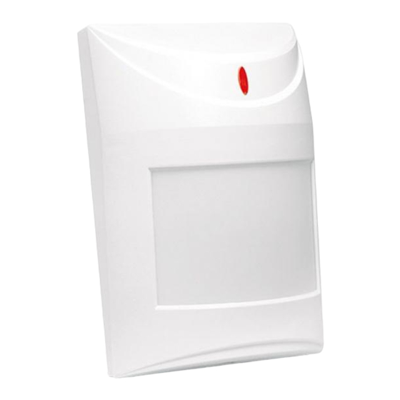
- Page 1 Digital passive infrared detector AQUA S Firmware version 4.00 aqua_s_en 07/23 SATEL sp. z o.o. • ul. Budowlanych 66 • 80-298 Gdańsk • POLAND tel. +48 58 320 94 00 www.satel.pl...
- Page 2 Changes, modifications or repairs not authorized by the manufacturer shall void your rights under the warranty. SATEL aims to continually improve the quality of its products, which may result in changes in their technical specifications and software. Current information about the changes being introduced is available on our website.
-
Page 3: Table Of Contents
CONTENTS Features ........................... 2 Specifications ........................2 Description ........................2 Supply voltage control ...................... 3 LED indicator ........................3 Electronics board ......................3 Terminals .......................... 4 Selecting a mounting location ................... 4 Installation ........................4 Start-up and walk test ....................... 7... -
Page 4: Features
AQUA S SATEL The AQUA S detector detects motion in the protected area. This manual applies to the detector with electronics version 4.2. 1. Features • Motion detection with passive infrared sensor (PIR). • Selectable detection sensitivity. • Digital motion detection algorithm. -
Page 5: Supply Voltage Control
SATEL AQUA S Supply voltage control When the voltage drops below 9 V (± 5%) for more than 2 seconds, the detector will indicate a trouble. The trouble is indicated by the alarm output and the LED turning on. Signaling will continue as long as the trouble exists. -
Page 6: Terminals
AQUA S SATEL Terminals - alarm output (NC relay). TMP - tamper output (NC). 24V - 12...24 VAC/DC power input. 5. Selecting a mounting location • Do not install the detector outdoors (A). • Install the detector at the recommended height (B). - Page 7 SATEL AQUA S 3. Make the openings for screws (Fig. 7 and 8) and cable (Fig. 9) in the enclosure base. 4. Pass the cable through the prepared opening. 5. Secure the enclosure base to the wall (Fig. 7) or a bracket fastened with screws to the wall or ceiling (Fig.
- Page 8 AQUA S SATEL 6. Fasten the electronics board. The scale next to the mounting screw hole facilitates positioning of the electronics board, depending on the detector installation height (Fig. 10). 7. Connect the wires to the corresponding terminals. 8. Configure the detector settings.
-
Page 9: Start-Up And Walk Test
SATEL AQUA S 7. Start-up and walk test The LED indicator should be enabled during the walk test. 1. Power on the detector. The LED will be flashing for 30 seconds to indicate warm-up of the detector. 2. When the LED stops flashing, check if moving within the detector coverage area will make the LED to light up. - Page 10 AQUA S SATEL Fig. 13 shows the detection range of the AQUA S detector with the factory-installed wide-angle EWA lens. You can install a different lens. The lenses offered by SATEL: − LR – long range lens with access zone monitoring: range 30 m; main beam 3 m wide at the end of range.
Need help?
Do you have a question about the AQUA S and is the answer not in the manual?
Questions and answers