Chapters
Table of Contents
Troubleshooting

Related Manuals for burmeier Lippe IV slatted frame


Summary of Contents for burmeier Lippe IV slatted frame
- Page 1 Lippe IV slatted frame Instruction Manual Part A: General Information Part B: Operator and Technical Personnel Part C: Care staff, residents and private purchasers 2022-04-21 | Version 07 | 301594 178629...
- Page 2 Part A: General Information...
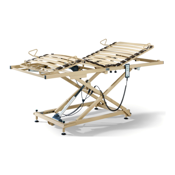
- Page 3 [1] Backrest [2] Backrest motor [3] Thigh rest [4] Lower leg rest [5] Mattress retainer bar (4x) [6] Mattress base frame [7] Lower leg rest ratchet mechanism [8] Guide rails (2x) l [9] Height adjustment motor [10] Feet (4x) [11] Bed chassis [12] Fixing lugs (4x) [13] Thigh rest motor [14] Retaining brackets (2x)
-
Page 5: Table Of Contents
Contents Part A: General Information Address, Market Information..................1 Address, market information......................1 Foreword......................... 2 Conventions of this Instruction Manual............... 3 Safety information..........................3 Icon information..........................4 Product Description....................... 5 Use for the intended purpose......................5 Contraindications..........................6 Components of the bed........................7 4.3.1 Mattress base frame......................7 4.3.2... -
Page 7: Part A: General Information
Address, Market Information Address, market information Manufacturer Burmeier GmbH & Co. KG (A Stiegelmeyer-Group company) Industriestraße 53 • 32120 Hiddenhausen / Germany Tel.:+49 (0) 5223 9769 - 0 • Fax:+49 (0) 5223 9769 - 090 Email:info@burmeier.com Internet:www.burmeier.com Service centre To order replacement parts in Germany and for any servicing requirements or other ques- tions, please contact our service centre: Burmeier GmbH &... -
Page 8: Foreword
Even after you have purchased a bed, Burmeier is still on hand to help at any time. We pro- vide customised solutions in all matters relating to inspection and maintenance, repair and process optimisation. -
Page 9: Conventions Of This Instruction Manual
Conventions of this Instruction Manual Safety information At the time of delivery, the Lippe IV slatted frame represents state-of-the-art technology and has been tested by an independent testing institute. Only use the slatted frame if it is in perfect working order. -
Page 10: Icon Information
Conventions of this Instruction Manual The safety symbols used are not a substitute for the written safety information. It is important therefore to read the safety information and follow the instructions exactly! Icon information General information and cross-references will be displayed in the following way: General information, tips and helpful courses of action. -
Page 11: Product Description
Use for the intended purpose • The Lippe IV slatted frame, hereafter referred to as the slatted frame/bed, is a comfort- able solution for positioning and facilitating the care of frail persons in need of care in homes for the elderly or nursing homes. Furthermore, it was developed as a supporting solution for home care, for infirm, disabled or frail persons. -
Page 12: Contraindications
Product Description Weight of accessories (incl. mattress) Maximum permitted weight of resident 10 kg 190 kg 40 kg 160 kg • Please refer to the safety information provided in the chapter Part B: Safety Informa- » tion 3, especially in the case of residents in poor clinical condition. •... -
Page 13: Components Of The Bed
Product Description CAUTION Trapping hazard Failure to heed this warning may result in injuries to the resident. • Owing to the smaller limbs of residents with a body height/weight that is less than this, there is an increased risk of entrapment between the open spaces of the safety sides when safety side systems are used. -
Page 14: Technical Data
Product Description The switch mode power supply provides all drives (motors) with protective low voltage using a connection cable and a cable harness. The socket available on the chassis is protected against the ingress of water. • A handset with a strong hook. The user can lock the adjustment options on the handset if the poor clinical condition of the resident necessitates this. - Page 15 Product Description Explanation of the graphical symbols used: The article is a medical device Device with type BF applied part in accordance with IEC 601-1 (special protection against electric shock) Protection Class II device, shock-proof Only for use in enclosed spaces – do not use outdoors Dispose of electrical components in accordance with the WEEE Direc- tive.
-
Page 16: Pid Bar Code
Product Description Explanation of the graphical symbols used: Only use mattresses that are approved by the manufacturer. Lock the handset if the resident could be at risk due to inadvertent mo- torised adjustments. 4.4.2 PID bar code The additional PID bar code on the bed includes a number that clearly identifies each partic- ular bed. -
Page 17: Adjustment Ranges
Product Description Mattress base size Total weight Safe working load 100 x 200 approx. 77.8 kg 200 KG 100 x 190 approx. 80.2 kg 200 KG 80 x 200 approx. 76.2 kg 200 KG 80 x 190 75.4 kg 200 KG Dismantled slatted frame: Mattress base frame Bed chassis... -
Page 18: Classification
Product Description Relative humidity Min. 20 %, max. 80 % (at 30°C; non-condensing. At altitude ≤ 2000m) Air pressure (at altitude ≤ 3000 m) Min. 700 hPa, max. 1060 hPa 4.4.7 Classification • This slatted frame fulfils all the requirements of the Medical Device Regulation (EU) 2017/745 (MDR) •... - Page 19 Product Description Switch mode power Lippe IV Lippe IV washable supply Classification Protection class 2 Handset with locking Lippe IV Lippe IV washable function Type Linak HL 74 Linak HL 74-261 Protection category IP X4 IP X6 Motors for mattress Lippe IV Lippe IV washable base height...
-
Page 20: Information On Electromagnetic Compatibility (Emc)
Failure to heed this warning may result in malfunctions. • The use of accessories, transducers and cables other than those supplied by BURMEIER for this bed may result in increased electromagnetic emissions or reduced electromagnet- ic immunity of the bed and may lead to incorrect operation. - Page 21 Product Description Ambient limit values of the interference emissions Phenomenon Home healthcare environment Conducted and radiated interference emissions CISPR 11 Harmonic distortions See IEC 61000-3-2 Voltage fluctuations and flicker See IEC 61000-3-3 Sheathing Phenomenon EMC basic standard Immunity level (test + compli- or test method ance) Home healthcare environment...
- Page 22 Product Description AC port for supply input Phenomenon EMC basic standard Immunity level (test + compli- ance) Home healthcare environment Voltage dips IEC 61000-4-11 0% UT; 1/2 period; at 0, 45, 90, 135, 180, 225, 270 and 315 degrees 0% UT; 1 period; and 70% UT; 25 periods;...
-
Page 23: Electrical Connection Diagram
Product Description Table zz: Test specifications for the immunity of sheathings to high-frequency wire- less communication equipment Test fre- Frequen- Radio serv- Modulation Max. Distance Immunity quency cy band power W test level 430 to 470 GMRS 460 FM +/- 5% FRS460 deviation, 1kHz sine... - Page 24 Product Description Part Image2: Location of the electrical components A: Head end, high up B: Centre of bed, high up C: Foot end, high up D: Head end, low down E: Centre of bed, low down F: Foot end, low down 4.4.10.1 Standard features The letters in the following tables refer to the previous picture “Location of the electrical...
- Page 25 Product Description 1: Power supply → E 2: Height adjustment motor → E 3: Thigh rest motor → B 4: Backrest motor → B 5: Handset → B Part A: General Information...
- Page 26 Part B: Operator and Technical Per- sonnel...
- Page 27 [1] Backrest [2] Backrest motor [3] Thigh rest [4] Lower leg rest [5] Mattress retainer bar (4x) [6] Mattress base frame [7] Lower leg rest ratchet mechanism [8] Guide rails (2x) l [9] Height adjustment motor [10] Feet (4x) [11] Bed chassis [12] Fixing lugs (4x) [13] Thigh rest motor [14] Retaining brackets (2x)
- Page 29 Contents Part B: Operator and Technical Personnel Target Groups, Qualifications and Duties..............1 Target groups of the commercial sector..................1 1.1.1 Operator..........................1 1.1.2 Technical Personnel......................2 Target group of the private sector....................2 1.2.1 Private purchasers....................... 2 Safety Information......................3 General information.........................
- Page 30 3.3.6 Mattress retainer bars......................22 Assembly accessories........................23 3.4.1 Spacers..........................23 3.4.2 Safety side..........................23 3.4.3 Mattress retainer bar (long)....................24 3.4.4 Patient lifting pole and triangular handle................24 Putting into Service...................... 25 Making Ready for Operation......................25 Cleaning and Disinfection....................26 Safety information on cleaning and disinfection................ 26 Cleaning and disinfection plan.....................
- Page 31 10.1 Disposal of the slatted frame......................46 10.2 Disposal of Packaging........................46 10.3 Disposal of electrical components....................46 Appendix........................47 11.1 Accessories............................ 47 11.1.1 Mattress requirements......................47 11.1.2 Safety side requirements....................48 11.2 Translation of EC Declaration of Conformity................48...
-
Page 33: Target Groups, Qualifications And Duties
Target Groups, Qualifications and Duties Target groups of the commercial sector 1.1.1 Operator Operators (e.g.: medical equipment retailers, specialist dealers, health insurance) are all nat- ural or legal persons who use this slatted frame or on whose behalf it is used. It is a require- ment that the operator duly instructs care staff in its use. -
Page 34: Technical Personnel
If any other equipment is attached to the bed, (e.g. compressors for positioning systems, etc.), ensure that this is securely fastened and is functioning properly. If anything is unclear, please contact the manufacturer of the device, or Burmeier. 1.1.2 Technical Personnel Technical personnel are persons who, based on their training or briefing, are qualified to de- liver the slatted frame, assemble or dismantle it and to transport it. -
Page 35: Safety Information
This instruction manual contains safety information which must be followed. All per- sons who work on or with the Lippe IV slatted frame must be familiar with the contents of this instruction manual and must follow the safety information. -
Page 36: Electrical Cables And Connections
Safety Information 2.2.1 Electrical cables and connections WARNING Risk of electric shock Failure to heed this warning may result in fatal injuries. Damaged mains cables can cause fatal electric shocks. Take the following measures to pre- vent hazards due to electric shock and malfunctions. •... -
Page 37: Operating Time Of Electric Drives
Safety Information 2.2.2 Operating time of electric drives Continuous operation must not exceed two minutes! After this time, a rest period of at least 18 minutes must be observed. If the electric drive is operated for a much longer pe- riod, e.g. -
Page 38: Adjusting The Slatted Frame
Safety Information • Do not leave children unsupervised in the room with the bed. • Adjustments may then be made only by, or in the presence of, a person who has received appropriate instruction. 2.2.4 Adjusting the slatted frame CAUTION Risk from movable parts Failure to heed this warning may result in injuries. -
Page 39: Special Hazards
Safety Information If the load is too high, an electronic overload switch is activated and the control unit is automatically switched off. When the excess load is removed, the drive unit system can be reactivated by pressing the appropriate button on the handset. Special Hazards 2.3.1 Risk of Fire... -
Page 40: Safety Information For Attachments And Additional Equipment
• Efficient and safe operation combined with maximum protection of residents can only be guaranteed if original Burmeier accessories designed for the relevant model of bed are used! Part B: Operator and Technical Personnel... -
Page 41: Safety Information For Disposal
Safety Information Safety Information for Disposal WARNING Risk of infection Beds, bed components or accessories that have not been disinfected can become health hazards for people. • The operator must ensure that all components of the bed that are to be disposed of are not infectious or contaminated. -
Page 42: Assembly
• Helpful assembly videos for setting up the bed can be found on www.burmeier.com/de/information/downloads or directly on YouTube. Please scan the following QR code with your mobile device: Included in the package The bed is delivered unassembled. The assembly work can be carried out by one or two per- sons. -
Page 43: Location Requirements
Pay particular atten- tion here to the safe routing of all loose connector cables, tubing, etc. If you have any questions or concerns, consult the manufacturer of the additional equipment or BURMEIER. To find the address, refer to Part B: Replacement »... - Page 44 Assembly Please note: The connection socket for the 6-pin plug of the switch mode power sup- ply is equipped with a pull-out prevention device [1] . • Pull up the pull-out prevention device [1] to release the retaining element. • Pull the sealing plug [2] out of the connection socket.
-
Page 45: Fit The Mattress Base Frame To The Chassis
Assembly Route the cable of the switch mode power supply unit safely (below the longitudinal struts of the chassis) within the bed surround [5]. Reinsert the plug of the switch mode power supply into a mains socket. 3.3.2 Fit the mattress base frame to the chassis Two retaining brackets are ready-attached to the head-end half of the mattress base frame in the factory. - Page 46 Assembly Move the scissor-type supports on the chassis until the V-pipe is about 5 cm higher than the upper edge of the bed surround [5]. Part B: Operator and Technical Personnel...
- Page 47 Assembly Hold the head-end half of the mattress base frame upright [6] and insert the pipe sock- et of the left-hand retaining bracket [7] into the open end of the V-pipe [8] as far as it will go. Now attach the right-hand retaining bracket that you removed earlier [9]. •...
- Page 48 Assembly Now take the foot-end half of the mattress base frame and lift it over the head-end half of the mattress base frame. Fit both halves of the mattress base frame together [11]. Tighten the four knurled screws (by hand) [12]. Now tilt the entire mattress base frame over into a horizontal position [13].
-
Page 49: Adjusting The Guide Cylinders
Assembly 3.3.3 Adjusting the guide cylinders The chassis is equipped with pull-out guide cylinders on the right and left-hand sides at the foot end. The guide cylinders slide on guide rails provided for this purpose, which are welded to the mattress base frame. After fitting the mattress base frame to the chassis, the guide cyl- inders must be extended up to the marking. - Page 50 Assembly Part B: Operator and Technical Personnel...
-
Page 51: Connecting Up The Drive Motors
Assembly 3.3.4 Connecting up the drive motors ATTENTION Material damage Incorrectly routed or damaged connection cables can lead to malfunctions or system failure. • Route the mains cable and all other cables from additional devices in such a way that they cannot be pulled, driven over or damaged by moving parts, or in any other way, when the bed is operated. -
Page 52: Attaching The Slatted Frame To The Bed Surround (Bed Frame)
Assembly 3.3.5 Attaching the slatted frame to the bed surround (bed frame) Lower the mattress base frame with the motor to determine the distances between the bed surround and the mattress base frame. Place the slatted frame so that there is a uniform amount of free space all round. - Page 53 Assembly • Loosen the knurled screws on the 4 fixing lugs [2]. • Pull out the fixing lugs until they are positioned up against the bed surround [3]. • Swivel the fixing lugs upwards a little (if necessary) to enable the wood screws to be inserted into the holes and then screw them into the bed surround.
-
Page 54: Mattress Retainer Bars
Assembly [A]: Minimum distance of 2.5 cm between the mattress base frame and the bed surround. The mattress base frame can be raised 7 cm with the foot raisers that are available as accessories. 3.3.6 Mattress retainer bars The mattress retainer bars are ready-fitted in the factory. They can be adjusted to a mattress width of 90 cm and 100 cm if required. -
Page 55: Assembly Accessories
Assembly Assembly accessories 3.4.1 Spacers If the height of the bed surround requires the chassis to stand at a higher level, spacers are available to extend the feet. • First, unscrew the feet that were fitted in the factory. • Next, screw the spacers into the chassis and then screw the feet onto the spacers. -
Page 56: Mattress Retainer Bar (Long)
Assembly 3.4.3 Mattress retainer bar (long) If a very high mattress is used, the mattress retainer bars supplied can be exchanged for ex- tra long mattress retainer bars. • Dismantle the short mattress retainer bars • Loosen the two hexagon socket head screws on each of the mattress retainer bars. -
Page 57: Putting Into Service
Putting into Service Making Ready for Operation Allow the slatted frame to adjust to room temperature for about 20 minutes if it was stored beforehand at the lowest or highest permissible temperature. After the slatted frame has been assembled, carry out a check in accordance with the chap- »... -
Page 58: Cleaning And Disinfection
Cleaning and Disinfection Safety information on cleaning and disinfection Cleaning is the most important measure and requirement for ensuring successful chemical disinfection. When the bed is occupied by the same resident, routine cleaning of the bed is generally suffi- cient. Disinfection of the chassis is only necessary if it has been visibly contaminated with infec- tious or potentially infectious materials (blood, stool, pus etc.) or if the doctor requires this due to the presence of an infectious disease. -
Page 59: Cleaning And Disinfection Plan
Cleaning and Disinfection • The electrical components must not be subjected to a jet of water, a high pressure cleaner or other similar devices! Clean only with a moist cloth (at most with pressure-less splash water)! • If you suspect that water or any other form of moisture has penetrated the electrical com- ponents, unplug the power plug immediately or do not plug it back into the socket. - Page 60 Cleaning and Disinfection • Remove any accessories (e.g. patient lifting pole), if available. • Check whether the housing of the drive components are undamaged (visual inspec- tion). • Move the backrest, thigh rest and lower leg rest into their lowest position. •...
-
Page 61: Instruction Of Care Staff And Technical Personnel
Cleaning and Disinfection Instruction of Care Staff and Technical Personnel In order to ensure that cleaning and disinfection are conducted properly, we recommend that users and staff are appropriately instructed. They should be instructed to observe the follow- ing points: •... - Page 62 For further informa- tion, consult BURMEIER or a specialist dealer of your choice. • Disinfectants based on compounds that could potentially release chlorine may be corro- sive for metals, synthetics, rubbers and other materials over longer contact periods or when concentrations are too high.
-
Page 63: Handling Cleaning And Disinfection Agents
Cleaning and Disinfection Handling Cleaning and Disinfection Agents • Follow the instructions for use for the particular products and their manufacturer. Pay attention to the exact dosage! We recommend the use of automated dosing instru- ments. • Always prepare solutions with cold water in order to avoid the formation of vapours which are mucous membrane irritants. -
Page 64: Maintenance
Maintenance Legal principles Operators of medical beds in Europe are obliged, in accordance with the new Medical Device Regulation (EU) 2017/745 (MDR) and existing relevant national laws/regulations, e.g. in Ger- many currently the • German Medical Devices Operator Ordinance § 7 (Maintenance) •... -
Page 65: Inspections And Function Checks
Maintenance CAUTION Hazards due to damage to property Damage, defects and wear resulting from improper operation and after long-term use can- not be ruled out. These defects can cause hazards. • if they are not recognised and corrected immediately. To this end, there are legal requirements for conducting regular inspections in order to guar- antee the safe condition of this medical product. -
Page 66: Operating Current Test Procedure
BURMEIER offers leakage current testing of switch mode power supply units as a serv- ice. To take advantage of this, the power supply units must be sent to BURMEIER. You will receive tested switch mode power supply units in return. Contact us for further de- »... -
Page 67: Inspection Report
Unplug the 24-volt power supply cable from the socket. • Insert the plug of the 24-volt cable into the measuring adapter (special accessory, available from BURMEIER on request). • Connect the measuring adapter to the “test probe” or similar socket of the test de- vice. - Page 68 Location: Serial number: Application environment (IEC60601-2-52): [ ] 1 [ ] 2 [x] 3 [x] 4 [ ] 5 Manufacturer: Burmeier GmbH & Co. Applied parts: Mattress base Testing equipment used (type/inven- tory no.): Medical Device Regulation classifica- tion: Class I I.
- Page 69 Maintenance Inspection report Visual inspection of the mechanical components Stickers and type plates Present, legible Patient lifting pole, adapter Damage, deformation sleeves Bed frame Damage, deformation Sprung slats Damage, splinters Feet Damage Mattress base Damage, deformation Wooden surround Damage, splinters Welded seams Split welded seams Safety side bars...
- Page 70 Maintenance Inspection report Result: Bed prot. ≥ 70 MΩ MΩ class II (type BF) Leakage current (direct or differential current measure- Description of de- ment) (type BF) fect Proceed as follows: Plug the mains cable/switch mode power supply into the test socket of the measuring instrument. Connect the probe of the measuring instrument to the bed;...
- Page 71 Maintenance Inspection report Motors Abnormal noise develop- ment (rattling, uneven run- ning) Strain relief of mains cable (if mains Mains cable firmly fas- cable available) tened Functional check of the mechanical components Joints and pivots Smooth operation Grab handle with strap Securely fixed when load tested under approx.
-
Page 72: Replacement Parts
Expert: Replacement parts The relevant replacement parts are available from BURMEIER, by specifying the item num- ber, order number and serial number. You will find the necessary details by referring to the type plate and the PID number, which is located on the mattress base frame at the head end. - Page 73 Maintenance Burmeier GmbH & Co. KG (A Stiegelmeyer-Group company) Industriestraße 53, 32120 Hiddenhausen Tel.: +49 (0) 5223 9769 - 0 Fax: +49 (0) 5223 9769 - 090 Email: info@burmeier.com Part B: Operator and Technical Personnel...
-
Page 74: Replacement Of Electrical Components
Replacement of electrical compo- nents Safety information WARNING Risk of electric shock Failure to heed this warning may result in injuries. • Before commencing any work on electrical equipment, always unplug the mains cable from the electrical socket! • Any work and/or repairs to the electrical equipment may only be carried out by the service engineers, the drive manufacturer or qualified and authorised electricians in compliance with all the relevant VDE and safety regulations! WARNING... -
Page 75: Replace The Handset With A New One
Replacement of electrical components Replace the handset with a new one Unplug the switch mode power supply unit from the electrical socket. Unplug the coiled handset cable from the socket under the mattress base. Route the cable of the new handset in such a way that it cannot be damaged by any moving parts of the slatted frame. -
Page 76: Troubleshooting
Troubleshooting Faults and their rectification Simple faults and problems can often be rectified by trained care staff using the troubleshoot- » ing table in this instruction manual. Please refer to the Part C: Troubleshooting 18. In all other cases, the operator and/or the technical personnel for maintenance and repairs are re- sponsible for rectifying malfunctions and faulty components. -
Page 77: Dismantling The Slatted Frame
Dismantling the slatted frame Move the backrest and thigh rest simultaneously into a horizontal position. Take the wood screws that grip the bed surround out of the fixing lugs. Loosen the knurled screws on the fixing lugs. • Slide the fixing lugs onto the chassis as far as they will go. •... -
Page 78: Disposal
As a result, commercial operators are obliged to send these components directly to the man- ufacturer. BURMEIER and its service and sales partners will take these components back. The return of these components is covered by our General Terms and Conditions. -
Page 79: Appendix
Appendix 11.1 Accessories The slatted frame must only be operated with original BURMEIER accessories. Burmeier does not accept any responsibility for accidents, defects and hazards that arise from the use of other accessories. WARNING Risk of injury Failure to heed this warning may result in danger to residents . -
Page 80: Safety Side Requirements
11.2 Translation of EC Declaration of Conformity We, Burmeier GmbH & CO. Burmeier GmbH & Co. KG, in our sole responsibility as the man- ufacturer, hereby declare that this product complies with the provisions of REGULATION (EU) 2017/745 OF THE EUROPEAN PARLIAMENT AND THE COUNCIL of 5 April 2017 (MDR). - Page 81 Appendix Part B: Operator and Technical Personnel...
- Page 82 Part C: Care staff, residents and pri- vate purchasers...
- Page 83 [1] Backrest [2] Backrest motor [3] Thigh rest [4] Lower leg rest [5] Mattress retainer bar (4x) [6] Mattress base frame [7] Lower leg rest ratchet mechanism [8] Guide rails (2x) l [9] Height adjustment motor [10] Feet (4x) [11] Bed chassis [12] Fixing lugs (4x) [13] Thigh rest motor [14] Retaining brackets (2x)
- Page 85 Contents Part C: Care staff, residents and private purchasers Target Groups, Qualifications and Duties..............1 Care staff............................1 1.1.1 Duties of care staff....................... 1 Resident............................2 Private purchasers........................... 2 Safety Information......................3 Safety information for operating the slatted frame............... 3 2.1.1 Electrical cables and connections..................
- Page 86 3.5.1 Raising by Hand......................... 15 3.5.2 Lowering by hand....................... 15 3.5.3 Lowering using the handset....................16 3.5.4 Raising using the handset....................16 Emergency release of the backrest....................16 Troubleshooting......................18 Maintenance........................20 Servicing points..........................20 Inspection activities........................21 Cleaning and disinfection.................... 23...
-
Page 87: Target Groups, Qualifications And Duties
Care staff are persons who, based on their training, experience or briefing, are qualified to operate the Lippe IV slatted frame on their own authority or to carry out work on the slatted frame, or have been instructed how to handle the slatted frame. Furthermore, care staff are able to recognise and avoid potential hazards and assess the clinical condition of the resi- dent. -
Page 88: Resident
Target Groups, Qualifications and Duties CAUTION Risk of injury Failure to heed this warning may result in injuries. • If any damage or malfunction is suspected, take the slatted frame out of service. • Unplug the bed from the mains supply immediately. •... -
Page 89: Safety Information
Safety Information Safety information for operating the slatted frame 2.1.1 Electrical cables and connections WARNING Risk of electric shock Damaged mains cables and/or switch mode power supply units pose a potentially lethal hazard due to electric shock. Take the following measures to prevent hazards due to electric shock and malfunctions. -
Page 90: Operating Time Of Electric Drives
Safety Information • Do not continue to use the slatted frame if you suspect that the mains cable and/or switch mode power supply unit could be damaged. • Ensure that the mains cable and the handset cable cannot be trapped or damaged in any other way (such as being chewed by pets) and that children cannot be strangled by them. -
Page 91: Adjusting The Slatted Frame
Safety Information • the resident is unable to operate the slatted frame safely, • the resident is unable to free himself or herself from potentially dangerous situations, • the resident is exposed to an increased risk of entrapment during backrest and thigh rest adjustments when the safety sides are raised, •... -
Page 92: Safety Information For Attachments And Additional Equipment
Safety Information ATTENTION Material damage Failure to heed this warning may result in the slatted frame being damaged, which could have an adverse effect on the loading capacity of the slatted frame or the adjusting func- tions. Ensure that • No obstacles such as bedside cabinets, supply rails, other equipment, chairs or wall pro- tection rails are in the way, •... -
Page 93: Safety Information For Accessories
Failure to heed this warning may result in injuries. • Efficient and safe operation combined with maximum protection of residents can only be guaranteed if original Burmeier accessories designed for the relevant model of slatted frame are used! Safety information for the user, resident, private purchaser Ensure that the operator/specialist dealer/your medical supply store instructs you in the safe operation of this slatted frame. - Page 94 Safety Information Unfavourable conditions of use Prevention through Interfering devices/objects close to the slatted frame Fire hazard due to heat generated by a reading Use only LED reading lamps that do not heat lamp, heater etc. up. Use devices only if they are in good working order and are used in accordance with their op- erating instructions;...
-
Page 95: Operation
Operation Handset 3.1.1 Using the handset This slatted frame is only intended for use as a slatted frame for a single bed. Keep a minimum safety distance of one bedside cabinet width (approximately 60 cm) between one bed and the next. The bed’s electrical adjustment mechanisms can be controlled with the handset. -
Page 96: Locking Functions
Operation Adjusting the backrest This button can be used to change the backrest's level of elevation. Adjusting the mattress base height This button can be used to change the mattress base's height. Adjusting the thigh rest This button can be used to change the angle of the thigh rest. - Page 97 Operation CAUTION Material damage Failure to heed this warning may result in material damage. • Do not forcibly turn the locking key beyond the limit stop of the lock! The lock or the entire handset can be damaged. ATTENTION Risk of injury Failure to heed this warning may result in injuries.
-
Page 98: Patient Lifting Pole (Accessory)
Operation Patient lifting pole (accessory) WARNING Risk of injury Failure to heed this warning may result in injuries. • The maximum loading capacity at the front end of the patient lifting pole is 75 kg. • The patient lifting pole is not suitable for rehabilitation exercises. A patient lifting pole [e] attached to the slatted frame makes it easier for the resident to get in and out of bed. -
Page 99: To Insert/Remove
Operation 3.2.1 To Insert/Remove Insert Insert the lifting pole in the sleeve. The metal pin [b]on the pole must be located in the notch [a]in the retainer sleeve. Remove Pull the lifting pole up and out of the sleeve. 3.2.2 Slewing range Part Image2:... -
Page 100: Triangular Grab Handle (Accessory)
Operation Triangular grab handle (accessory) A triangular grab handle can be attached to the lifting pole. The resident can use this grab handle to sit up and readjust his/her position more easily. Check the grab handle and belt » regularly for damage (see Part C: Maintenance 20). -
Page 101: Safety Sides (Accessory)
Operation The maximum loading capacity at the front end of the lifting pole is 75 kg. • The height of the triangular grab handle can be adjusted using the strap. • Make sure that the strap is correctly threaded through the buckle. •... -
Page 102: Lowering Using The Handset
Operation Raise the lower leg rest to its full extent. Then lower the lower leg rest slowly. If the thigh rest is lowered using the handset, the lower leg rest is automatically lowered as well. 3.5.3 Lowering using the handset If the thigh rest is lowered using the handset, the lower leg rest is automatically lowered as well. - Page 103 Operation Release the load on the backrest before carrying out the CPR release procedure. To do so, the first carer raises the backrest slightly by gripping the outside edge of the head section and holds the backrest in this position. The second carer now removes the lock- ing pin [1].
-
Page 104: Troubleshooting
Troubleshooting The following table is a guide to rectifying faults: If malfunctions occur while the bed is in use, and care staff are unable to remedy them with the aid of the troubleshooting table, the main- tenance and repair personnel of the bed operator concerned must be informed. WARNING Life-threatening danger, risk of injury Failure to heed this warning may result in fatal injuries. - Page 105 Troubleshooting Problem Possible causes Solution Green LED contin- • Handset faulty → Replace handset uously alight; yel- • Switch mode power → Check plug connections low LED on the supply unit plug (24- power pack does → Enable functions (see Part C: Operating volt) not inserted prop- not light up when a...
-
Page 106: Maintenance
Maintenance As well as the extensive routine inspections performed by technical personnel, the bed must also be checked at shorter regular intervals by non-technical users (care staff, family carers etc.), and be briefly visually inspected and have its functions tested before being occupied by a new user. -
Page 107: Inspection Activities
Maintenance Inspection activities For private users, no regular inspections are specified. However, we recommend that you check all electrical and mechanical components once a year to ensure you will enjoy many years of trouble-free operation. When doing so, please use the following checklist. Check Description of Fault Visual inspection of the electrical components... - Page 108 Maintenance Check Description of Fault Lower leg rest Engages properly Accessories (e.g. pa- Fastening, damage tient lifting pole, trian- gular handle) Inspector’s signa- Inspection result: Date: ture: Part C: Care staff, residents and private purchasers...
-
Page 109: Cleaning And Disinfection
Cleaning and disinfection ATTENTION Risk of material damage Failure to observe this can lead to material damage! • Unplug the power cable and store the power plug so that it does not come into excessive contact with water or other cleaning solutions (place in a plastic bag). •... - Page 110 For further informa- tion, consult BURMEIER or a specialist dealer of your choice. • Disinfectants based on compounds that could potentially release chlorine may be corro- sive for metals, synthetics, rubbers and other materials over longer contact periods or when concentrations are too high.
- Page 111 Cleaning and disinfection Part C: Care staff, residents and private purchasers...
- Page 112 Burmeier GmbH & Co. KG Industriestraße 53 / D-32120 Hiddenhausen Telephone: +49 (0) 5223 9769 - 0 / Fax: +49 (0) 5223 9769 - 090 E-mail: info@burmeier.com www.burmeier.com...
Need help?
Do you have a question about the Lippe IV slatted frame and is the answer not in the manual?
Questions and answers