Table of Contents
Advertisement
Dali
Clinic | Care | Homecare | Living
Instruction Manual
Part A: General Information
Part B: Operator and Technical Personnel
Part C: Care staff and residents
REF: 221234
Information for clients
In addition to these Operating
Instructions, further product
information is available:
• "Lock-APP" application:
Can be downloaded from the
App and Play Store
2019-01-21 | Version 01 | 272846
Advertisement
Chapters
Table of Contents
Troubleshooting

Related Manuals for burmeier Dali


Summary of Contents for burmeier Dali
- Page 1 Dali Clinic | Care | Homecare | Living Instruction Manual Information for clients In addition to these Operating Instructions, further product Part A: General Information information is available: • "Lock-APP" application: Part B: Operator and Technical Personnel Can be downloaded from the...
-
Page 2: Part A: General Information
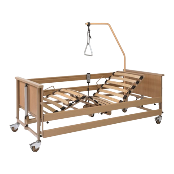
Part A: General Information... - Page 3 [1] Chassis footboard [2] Safety side release buttons (4) [3] Lower leg rest [4] Thigh rest [5] Handset [6] Triangular grab handle [7] Backrest [8] Patient lifting pole [9] Chassis headboard [10] Mattress retainers (4) [11] Guide rails (4) [12] Lifting pole sleeves (2) [13] Castors (4) [14] Control unit (concealed in picture) [15] Drive motors for backrest and...
-
Page 5: Table Of Contents
Explanation of the Graphical Symbols Used..............10 4.5.4 Materials Used........................11 4.5.5 Dimensions and Weights....................11 4.5.6 Adjustment Options......................12 4.5.7 Ambient Conditions......................12 4.5.8 Electrical Data: Dali standard, low-entry................14 4.5.9 Electrical Data: Dali econ, low....................16 4.5.10 Electrical Data: Dali wash....................17 4.5.11 Information on Electromagnetic Compatibility (EMC)............19... -
Page 7: Address, Information For Customers, Market Note
In addition to these Operating Instructions, further product information is available: • "Lock-APP" application:Can be downloaded from the App and Play Store. • “Burmeier” application:Can be downloaded from the App and Play Store. • Quick Guide:To operate the bed functions that are used most, can be downloaded from www.burmeier.de... -
Page 8: Foreword
Burmeier GmbH & Co. KG You are a medical product retailer and would like to get in touch with Burmeier? Feel free to phone us: Our customer care centre in Germany can be contacted at +49 (0) 5232 9841 - 0. -
Page 9: Conventions Of This Instruction Manual
Conventions of this Instruction Man- Safety Information At the time of delivery, the Dali care bed represents state-of-the-art technology and has been tested by an independent testing institute. Only use the Dali care bed if it is in perfect working order. -
Page 10: Icon Information
Conventions of this Instruction Manual Icon Information General information and cross-references will be displayed in the following way: General information, tips and helpful courses of action. Cross-reference or active link: Indicates the chapter name and page number of the instruc- tion manual where you will find what you are looking for. -
Page 11: Product Description
Furthermore, it was developed as a supporting solution for home care, for infirm, disabled or frail persons. It it designed to support this care. • The use of the Dali care bed in hospitals is only permitted in rooms designed for medi- cal treatment of the application group 0. •... -
Page 12: Contraindications
Product Description Weight of accessories Maximum permitted resident weight (incl. mattress) Dali (standard, low, econ, wash) Dali low-entry 20 kg 165 kg 155 kg • Please refer to the safety information provided in the chapter Part B: Safety Informa- »... -
Page 13: Components Of The Bed
Product Description BMI calculation: BMI = weight of resident (kg) / height of resident (m) Example a: 41 kg / (1.5 m x 1.5 m) = 18.2 = OK! Example b: 35 kg / (1.5 m x 1.5 m) = 15.6 = Not OK! CAUTION Trapping hazard •... -
Page 14: Electrical Adjustment System
• a drive motor for the backrest. Mattress Base Sizes The Dali care bed can be ordered in the following sizes. This instruction manual may describe functions or features that your model of bed does not have. Part A: General Information... -
Page 15: Technical Data
Product Description Mattress base dimensions (W x L) Outer dimensions (W x L) 90 x 200 cm (wood or metal mattress base) 101 x 218 cm Technical Data 4.5.1 Type Plate You can find the type plate on the bed frame at the head end. The type plate contains the following information: Part Image1: Type plate examples... -
Page 16: Explanation Of The Graphical Symbols Used
Product Description Part Image2: PID Number 4.5.3 Explanation of the Graphical Symbols Used Explanation of the graphical symbols used: Device with type BF applied part in accordance with IEC 601-1 (special protection against elec- tric shock) Protection Class II device, shock-proof Only for use in enclosed spaces - do not use outdoors Dispose of electrical components in accordance... -
Page 17: Materials Used
Product Description Explanation of the graphical symbols used: Safe working load Maximum permitted weight of resident Minimum measurements/weight of resident: Height: 146 cm, weight: 40 kg; body mass index “BMI”: 17 Only use mattresses that are approved by the manufacturer. Lock the handset if the resident could be at risk due to inadvertent motorised adjustments 4.5.4... -
Page 18: Adjustment Options
Product Description standard/econ wash low/low-entry Total weight, depending 92 to 97 kg on model Safe working load 185 kg 185 kg 175 kg Disassembled bed: Chassis with motors 34 kg Wooden mattress base 37 kg 37 kg frame with motors Metal mattress base 41 kg frame with motors... - Page 19 Product Description Storage temperature min. -10°C max.+ 50°C Relative humidity min. 20% max. 90% (at 30°C; non-condensing. At altitude ≤ 2000 m) Air pressure min. 800 hPa max. 1060 hPa In operation: Ambient temperature min. + 5°C max. + 40°C Relative humidity min.
-
Page 20: Electrical Data: Dali Standard, Low-Entry
Product Description 4.5.8 Electrical Data: Dali standard, low-entry Control unit Type: CBSTI 01 Operating voltage From external power supply type SMPS 12 or SMPS14 Output current Duty cycle Intermittent duty: 2 min ON / 18 min OFF Protection category IPX6... - Page 21 Product Description Handset with locking function (locks using a magnetic chip) Type HBSTI Protection category IPX6 Electric motor for mattress base height Type Linak LA 24 Force/lift 1400 N / 405 mm Input voltage 24 V DC Protection category IPX4 Duty cycle 2 min ON / 18 min OFF Electric motor for backrest...
-
Page 22: Electrical Data: Dali Econ, Low
Product Description 4.5.9 Electrical Data: Dali econ, low Control unit Type CA 40 Operating voltage 100 – 240 VAC, 50/60 Hz Current input Duty cycle Intermittent duty: 2 min ON / 18 min OFF Protection category IPX6 Classification Protection class 2... -
Page 23: Electrical Data: Dali Wash
2 min ON / 18 min OFF Electric motor noise generation Noise level during adjustments < 50 dB (A) 4.5.10 Electrical Data: Dali wash Control unit Type: CBSTI 01 Operating voltage From external power supply type SMPS 12 or SMPS14... - Page 24 Product Description Power pack Type SMPS12 SMPS14 Input voltage 230 VAC (-15% / +10%) 100-240 VAC, 50/60 Hz -15% / +10% Standby current consumption < 0.5 W Current input 1.8 A max. 3.5 A max. Output voltage 32 VDC 24 VDC Output current 4.5 A Duty cycle...
-
Page 25: Information On Electromagnetic Compatibility (Emc)
CAUTION • The use of accessories, transducers and cables other than those supplied by BURMEIER for this bed may result in increased electromagnetic emissions or reduced electromagnet- ic immunity of the bed and may lead to incorrect operation. - Page 26 Product Description • The use of HF surgery on the bed is prohibited as it may lead to unpredictable malfunc- tions of the bed. • The use of this device next to other devices should be avoided, as this could result in in- correct operation.
- Page 27 Product Description Sheathing Phenomenon EMC basic standard or Immunity test level test method Home healthcare environ- ment Magnetic fields with energeti- IEC 61000-4-8 See separate table zz (at the cally rated frequencies end of this chapter) AC port for supply input Phenomenon EMC basic standard Immunity test level...
- Page 28 Product Description DC port for supply input Phenomenon EMC basic standard Immunity test level Home healthcare environ- ment Conducted interference in- IEC 61000-4-6 3 V; 0.15 MHz to 80 MHz; 6V in duced by high-frequency fields ISM and amateur radio fre- quency bands between 0.15 MHz and 80MHz 80% AM at 1 Patients’...
- Page 29 Product Description Ports for signal input/signal output parts Phenomenon EMC basic standard Immunity test level Home healthcare environ- ment quency bands between 0.15 MHz and 80MHz 80% AM at 1 Table zz: Test specifications for the immunity of sheathings to high-frequency wire- less communication equipment Test Fre- Frequen-...
- Page 30 Product Description Table zz: Test specifications for the immunity of sheathings to high-frequency wire- less communication equipment Test Fre- Frequen- Radio Modula- Max. Distance Immunity quency cy band service tion power W test level b/g/n, RFID 2450, LTE band 7 5240 5100 to WLAN...
- Page 31 Product Description Part A: General Information...
- Page 32 Part B: Operator and Technical Per- sonnel...
- Page 33 [1] Chassis footboard [2] Safety side release buttons (4) [3] Lower leg rest [4] Handset [5] Thigh rest [6] Triangular grab handle [7] Backrest [8] Patient lifting pole [9] Chassis headboard [10] Mattress retainers (4) [11] Guide rails (4) [12] Lifting pole sleeves (2) [13] Castors (4) [14] Control unit (concealed in picture) [15] Drive motors for backrest and...
- Page 35 Contents Part B: Operator and Technical Personnel Target Groups, Qualifications and Duties..............1 Operators............................1 1.1.1 Responsibilities of the Operator................... 1 Technical Personnel.........................2 Safety Information......................3 General Information......................... 3 Safety Information for Operating the Bed..................3 2.2.1 Electrical Cables and Connections..................4 2.2.2 Operating Time of Electric Drives..................4 2.2.3...
- Page 36 3.7.1 Connector Assignment (standard/CBSTI 01)..............19 3.7.2 Connector Assignment (Dali econ/CA 40)................19 3.7.3 Connect to the Plug-In Power Pack................... 20 Putting into Service...................... 21 Power Pack Connection.........................21 Pairing the Bluetooth Handset...................... 22 Making Ready for Operation......................22 Cleaning and Disinfection....................24 Safety Information on Cleaning and Disinfection............... 24 Cleaning and Disinfection Plan.....................25...
- Page 37 Disposal.........................45 10.1 Disposal of the Bed........................45 10.2 Disposal of Packaging........................45 10.3 Disposal of Electrical Components....................45 Appendix........................46 11.1 Accessories............................ 46 11.1.1 Mattress Requirements...................... 46 11.1.2 Safety Side Requirements....................47 11.2 Translation of EC Declaration of Conformity................47...
-
Page 39: Target Groups, Qualifications And Duties
Operators (e.g.: medical equipment retailers, specialist dealers, health insurance) are all nat- ural or legal persons who use the Dali care bed or on whose behalf it is used. It is a require- ment that the operator duly instructs care staff in its use. -
Page 40: Technical Personnel
Target Groups, Qualifications and Duties Technical Personnel Technical personnel comprises persons who, based on their training or briefing, are qualified to deliver the care bed, assemble or dismantle it and to transport the bed. Furthermore, this personnel is briefed in the cleaning and disinfection instructions. Part B: Operator and Technical Personnel... -
Page 41: Safety Information
This instruction manual contains safety information which must be followed. All per- sons who work on or with the Dali care bed must be familiar with the contents of this instruction manual and must follow the safety information. -
Page 42: Electrical Cables And Connections
Safety Information 2.2.1 Electrical Cables and Connections WARNING Danger of electric shock Damaged mains cables can cause fatal electric shocks. Take the following measures to pre- vent hazards due to electric shock and malfunctions. • If a damaged mains cable continues to be used, this can lead to electric shock, fire and other hazards as well as malfunctions. -
Page 43: Handset
Safety Information tent of overloading, it may take a few minutes until you can carry out any further adjustments. Also read and note the additional information contained in the chapter Part C: Troubleshoot- » 2.2.3 Handset When not in use, stow the handset in such a way that it cannot inadvertently fall off (hang it up by the hook). -
Page 44: Bluetooth Handset
Safety Information 2.2.4 Bluetooth Handset CAUTION Risk of crushing Swapping the Bluetooth handset can lead to uncontrolled adjustment of the bed, e.g. from neighbouring rooms and therefore a risk of crushing and serious injury to the person lying in the bed. •... - Page 45 Safety Information • No obstacles such as bedside cabinets, supply rails, other equipment, chairs, wall protec- tion rails or sloping roofs are in the way, • There are no objects lying beneath the bed, • People do not sit on slightly raised sections of the backrest and leg rests. CAUTION Asynchronous drives Lifting drives that do not move synchronously cause the lying surface to be inclined.
-
Page 46: Special Hazards
Safety Information Special Hazards 2.3.1 Risk of Fire WARNING Risk of fire Various external factors can result in a fire. To prevent a fire, take the following precaution- ary measures: • Use only flame-retardant mattresses and bedding if possible. • Inform residents that smoking is not allowed in bed. -
Page 47: Safety Information For Attachments And Additional Equipment
• Efficient and safe operation combined with maximum protection of residents can only be guaranteed if original Burmeier accessories designed for the relevant model of bed are used! Part B: Operator and Technical Personnel... -
Page 48: Safety Information For Disposal
Safety Information Safety Information for Disposal WARNING Risk of infection Beds, bed components or accessories that have not been disinfected can become health hazards for people. • The operator must ensure that all components of the bed that are to be disposed of are not infectious or contaminated. -
Page 49: Assembling The Care Bed
Assembling the Care Bed This chapter is intended to be read by professionals employed by the operator or medical supply retailers. Tools An assembly key is supplied. Please note: An assembly key is included in the delivery of the bed. To ensure all bed components are securely tightened, all knurled-thumb screws of the bed must be tightened with the supplied assembly key (see illustration). -
Page 50: Mattress Base Brame
Before using the bed on parquet flooring, check whether the castors will leave stains on the parquet varnish. The bed can be used on tiles, carpet, linoleum or laminate flooring without causing any damage. BURMEIER is not liable for any damage caused by day- to-day operation on floors. -
Page 51: Chassis
Assembling the Care Bed Now take the foot end half of the mattress base frame and lift it over the head end half of the mattress base frame. Then insert the two halves of the mattress base frame to- gether. Tighten the 4 knurled-thumb screws only by hand only (do not use pliers!). -
Page 52: Safety Sides
Assembling the Care Bed Loosen the two knurled-thumb screws located below the mattress base frames next to the two patient lifting pole sleeves [12]. Do not completely remove the screws. Fit the chassis headboard [9] together with the mattress base frame [17]. Make sure that the adhesive labels match! •... - Page 53 Assembling the Care Bed Important: The guide rails [11] must be diagonal to each other before starting the assembly work (see picture). To do this, raise the guide rail at the head end and lower the guide rail at the foot end. Start with the chassis headboard on the right side of the bed and proceed as follows: •...
- Page 54 Assembling the Care Bed • Insert one end of the bar into the lower holding fixture (head end). • Insert the other end of the bar to the holding fixture (foot end). • The bar must be firmly clamped by means of the release button [b]. •...
-
Page 55: Electrical Connection
Assembling the Care Bed Electrical Connection Before you connect the cables, you must remove the packaging material from all of the ca- bles. The 4 drive motors are supplied with electricity by the power pack. All drive motor plugs are connected to the control unit at the factory and secured with a cover to prevent unintentional removal. - Page 56 [a]. • In the Dali econ: Screw the 230 V cable onto the small open tab of the strain re- lief as shown [b]. Part B: Operator and Technical Personnel...
-
Page 57: Connector Assignment (Standard/Cbsti 01)
Be sure to compare the numbers on the cables with the num- bers on the lifting motors before connecting them. 3.7.2 Connector Assignment (Dali econ/CA 40) Connector assignment for drive system with cable handset Backrest motor... -
Page 58: Connect To The Plug-In Power Pack
Assembling the Care Bed and 4 for the foot-end lifting motor). These numbers can be found on the connecting lines of the lifting motors accordingly. Be sure to compare the numbers on the cables with the num- bers on the lifting motors before connecting them. 3.7.3 Connect to the Plug-In Power Pack ATTENTION... -
Page 59: Putting Into Service
Putting into Service Power Pack Connection CAUTION Damage to power pack Failure to follow this information can result in irreparable faults to the power pack and a short-circuit in the wall socket. • The wall socket which you wish to use for the power pack must NOT be under the bed. Otherwise, the moving mattress base frame can rip the power pack out of the electrical socket during horizontal adjustments. -
Page 60: Pairing The Bluetooth Handset
Putting into Service Part Image1: Power Pack Connection Pairing the Bluetooth Handset In the Dali standard, wash and low-entry. Before the bed functions can be adjusted, the handset must be coupled (connected) with the control unit. Proceed as follows: Plug the power pack into the electric socket. - Page 61 Putting into Service After the bed has been assembled, carry out a check in accordance with the chapter Part B: » Maintenance Clean and disinfect the bed before it is used for the first time and before every re-use in ac- »...
-
Page 62: Cleaning And Disinfection
Cleaning and Disinfection Safety Information on Cleaning and Disinfection Cleaning is the most important measure and requirement for a successful chemical disinfec- tion. When the bed is occupied by the same resident, routine cleaning of the bed is generally suffi- cient. -
Page 63: Cleaning And Disinfection Plan
Destech procedure. Please see the documents of the company Destech for further information. 5.2.2 Automated Cleaning (Dali wash) To avoid adverse effects on the bed, it must be specially prepared for machine cleaning. The following steps are necessary to further guarantee the service life and functionality. -
Page 64: Instruction Of Care Staff And Technical Personnel
Cleaning and Disinfection Caution! After that, make sure that the socket for connecting the mains cable is closed with a plug. • Connect the plug of the drive motors to the lifting drive. Caution! Ensure that the plugs are correctly connected to prevent water from penetrat- ing the lifting drive. -
Page 65: Cleaning And Disinfection Agents
Despite the excellent mechanical resistance, any scratches, knocks etc. which perme- ate the entire coating should be resealed using a suitable repair substance to prevent moisture from penetrating. For further information, consult BURMEIER or a specialist dealer of your choice. -
Page 66: Handling Cleaning And Disinfection Agents
Cleaning and Disinfection lease chlorine may be corrosive for metals, synthetics, rubbers and other materials over lon- ger contact periods or when concentrations are too high. Furthermore, these disinfectants have a higher so-called protein effect, are mucous membrane irritants and demonstrate poor environmental compatibility. -
Page 67: Maintenance
Maintenance Legal Principles Operators of care beds in Germany are obliged in accordance with • German Medical Devices Operator Ordinance § 4 (Maintenance) • Berufsgenossenschafts-Vorschrift DGUV regulation 3 (Directive of the German Em- ployers Liability Insurance Association, Testing of mobile electrical equipment in indus- trial use) to preserve the safe operating condition of medical devices throughout their entire service life. -
Page 68: Inspections And Function Checks
• BURMEIER offers the leakage current test of power packs as a service. To take advantage of this, the power packs must be sent to BURMEIER. You will receive tested power packs in return. -
Page 69: Operating Current Test Procedure
Unplug the power pack 24 volt cable from the socket. • Insert the plug of the 24 volt cable into the measuring adapter (special accessory, available from BURMEIER on request). • Connect the measuring adapter to the “test probe” or similar socket of the test de- vice. -
Page 70: Inspection Report
Inventory number: Location: Serial number: Application environment (IEC60601-2-52): [ ] 1 [ ] 2 [x] 3 [x] 4 [ ] Manufacturer: Burmeier GmbH & Co. User-specific parts: none Testing equipment used (type/invento- ry no.): Medical Devices Act classification: Class I I. - Page 71 Maintenance Inspection Report Motor and handset ca- Damage, routing of ca- bles Cable harness/power Available, correct posi- pack sockets tion Visual Inspection of the Mechanical Components Stickers and type plates Present, legible Safe working load/ Present, legible weight of patient Patient lifting pole, adap- Damage, deformations tor sleeves...
- Page 72 Maintenance Inspection Report 2. Connect the probe of the measuring instrument to the bed; measuring point: Bare metal screw under backrest in frame of mattress base 3.) Activate the motors using the handset for the du- ration of the measurement. 4.
- Page 73 Maintenance Inspection Report Grab handle with strap Secure position Castors Moving and braking CPR release of backrest Test according to instruc- tion manual Safety side Securely engaged, secure position, unlocking Lower leg rest Engaged Accessories (e,g, patient’s lifting Fixture, damage, suitabili- pole, grab handle with belt) Inspection result: Inspection passed;...
-
Page 74: Replacement Parts
Replacement Parts The relevant replacement parts are available from BURMEIER, by specifying the item num- ber, order number and serial number. You will find the necessary details by referring to the type plate and the PID number, which is located on the mattress base frame at the head end. -
Page 75: Replacement Of Electrical Components
Replacement of Electrical Compo- nents Safety Information WARNING Danger of death due to electric shock! • Before commencing any work on electrical equipment, always unplug the mains cable from the electrical socket! • Any work and/or repairs to the electrical equipment may only be carried out by the service engineers, the drive manufacturer or qualified and authorised electricians in compliance with all the relevant VDE and safety regulations! WARNING... -
Page 76: Replace Cable Handset
Plug the new handset into the connection socket (for connection diagram, see Part B: » Connector Assignment (Dali econ/CA 40) • There is a recess on the plug of the handset. When inserting the plug, make sure that the recess points upwards. Make sure that the O-ring seal on the plug is not damaged;... -
Page 77: Replacing The Bluetooth Handset
Replacement of Electrical Components Replacing the Bluetooth Handset • Replacing the old handset with the new one. • After replacing the Bluetooth handset, it must first be paired with the bed control. » Part B: Pairing the Bluetooth Handset • After replacing the handset with a new one, test that the motorised adjustments are working! Pairing the new handset causes the old handset to be automatically decoupled from the con-... - Page 78 Replacement of Electrical Components • Open the battery compartment cover [a] on the back of the handset. • For example, insert a coin into the slot of the cover and turn it counter-clockwise. • Remove the old battery. • Insert the new battery (observe polarity). •...
-
Page 79: Troubleshooting
Troubleshooting Faults and their Rectification Simple faults and problems can often be rectified by trained care staff using the troubleshoot- » ing table in this instruction manual. Please refer to the Part C: Troubleshooting 24. In all other cases, the operator and/or the technical personnel for maintenance and repairs are re- sponsible for rectifying malfunctions and faulty components. -
Page 80: Dismantling The Care Bed
Dismantling the Care Bed The key to the letters shown in square brackets [x] in the following paragraph can be found in the chapter Assembling the Bed. Refer to this chapter for reference purposes when carrying out the dismantling work. Proceed as follows to dismantle the care bed: Apply the brakes to the castors on the bed. -
Page 81: Dismantling The Mattress Base Frame
Dismantling the Care Bed Dismantling the Mattress Base Frame Proceed as follows: Place the mattress base frame upright against a wall, head end facing down. Remove the locking pin from the lifting bar of the drive motor for the thigh rest. Loosen the knurled-thumb screws at the two connection points of the mattress base frame. -
Page 82: Mount The Dismantled Bed On The Storage Aid
Dismantling the Care Bed Mount the dismantled bed on the storage aid The storage aid connects the two chassis and supports the two halves of the mattress base frame. It also offers holders for the safety side bars and the patient lifting pole. Proceed as follows: •... -
Page 83: Disposal
The operator of this bed is legally obliged to return the electrical components directly to the manufacturer and not to dispose of them at municipal waste collection points. Burmeier and its service and sales partners will take these components back. The return of these compo- nents is covered by our General Terms and Conditions. -
Page 84: Appendix
Appendix 11.1 Accessories The bed must only be operated with original BURMEIER accessories. BURMEIER does not accept any responsibility for accidents, defects and hazards that arise from the use of other accessories. WARNING Risk of hazard for residents due to improper use of accessories Pay attention to the following information when using safety sides, infusion stands, etc. -
Page 85: Safety Side Requirements
Appendix 11.1.2 Safety Side Requirements Safety Side Requirements Height above mattress > 220 mm Gap between bars and mattress base < 120 mm Foam rubber density min. 40 kg/m Gap between safety side and chassis head- < 60 mm board Gap between safety side and chassis footboard >318 mm Permissible accessory safety sides:... - Page 87 Part C: Care staff and residents...
- Page 88 [1] Chassis footboard [2] Safety side release buttons (4) [3] Lower leg rest [4] Handset [5] Thigh rest [6] Triangular grab handle [7] Backrest [8] Patient lifting pole [9] Chassis headboard [10] Mattress retainers (4) [11] Guide rails (4) [12] Lifting pole sleeves (2) [13] Castors (4) [14] Control unit (concealed in picture) [15] Drive motors for backrest and...
- Page 90 Contents Part C: Care staff and residents Target Groups, Qualifications and Duties..............1 Care staff............................1 1.1.1 Duties of Care Staff......................1 Residents............................2 Safety Information......................3 Safety Information for Operating the Bed..................3 2.1.1 Electrical Cables and Connections..................3 2.1.2 Operating Time of Electric Drives..................4 2.1.3 Handset..........................
- Page 91 Triangular Grab Handle........................17 3.6.1 Service Life.........................17 3.6.2 Adjusting the Grab Handle....................17 Safety Sides............................ 18 Lower Leg Rest..........................20 3.8.1 Raising Using the Handset....................20 3.8.2 Lowering Using the Handset....................20 3.8.3 Raising by Hand (Option)....................20 3.8.4 Lowering by Hand (Option)....................21 CPR Release of the Backrest......................
-
Page 92: Target Groups, Qualifications And Duties
Care staff are persons who, based on their training, experience or briefing, are qualified to operate the Dali care bed on their own authority or to carry out work with the care bed, or have been instructed how to handle the care bed. Furthermore, they are able to recognise and avoid potential hazards and assess the clinical condition of the resident. -
Page 93: Residents
Target Groups, Qualifications and Duties CAUTION Risk of injury • If any damage or malfunction is suspected, take the bed out of service. • Unplug the bed from the mains supply immediately. • Indicate clearly that the bed is “OUT OF ORDER”. •... -
Page 94: Safety Information
Safety Information Safety Information for Operating the Bed 2.1.1 Electrical Cables and Connections WARNING Danger of electric shock Damaged mains cables and/or power packs pose a potentially lethal hazard due to electric shock. Take the following measures to prevent hazards due to electric shock and malfunc- tions. -
Page 95: Operating Time Of Electric Drives
Safety Information • Do not place multiple socket bars under the bed. This could cause electrical hazards due to damaged mains cables or penetrating fluids. • Do not continue to use the bed if you suspect that the mains cable and/or power pack could be damaged. -
Page 96: Bed Adjustments
Safety Information CAUTION Risk of injury Lock the operating functions for the resident on the handset if • The resident is unable to operate the bed safely, • The resident is unable to free himself or herself from potentially dangerous situations, •... -
Page 97: Power Pack
2.2.1 Use of Resident Lifts CAUTION • Efficient and safe operation combined with maximum protection of residents can only be guaranteed if original Burmeier accessories designed for the relevant model of bed are used! CAUTION Risk of injury • Make sure that the attachment of accessories does not produce any crush or shearing zones for the resident when the bed sections are adjusted. -
Page 98: Safety Information For Accessories
Safety Information for Accessories CAUTION Risk of injury • Efficient and safe operation combined with maximum protection of residents can only be guaranteed if original Burmeier accessories designed for the relevant model of bed are used! Part C: Care staff and residents... -
Page 99: Operation
Operation Handset Depending on the equipment, the Dali care bed can be equipped with Bluetooth handset or cable handset. All the bed's electrical adjustment mechanisms can be controlled with the handset [5]. The adjustment range for all functions is electrically/mechanically limited to the permitted ranges. -
Page 100: Bluetooth Handset
Operation Adjust the mattress base height whenever necessary, but at least once a day, to the upper- most or lowest height. This automatically equalises the two independent adjustment drives and results in a level horizontal mattress base. ATTENTION Damage to the bed / objects If the bed continues to be misaligned (ramped up) in the adjustment path due to overloading or obstacles (e.g. -
Page 101: Cable Handset
Operation The handset is powered by a CR 2032 lithium battery. When the battery capacity is getting low, the LED display on the handset flashes yellow 4 times each time the button is pressed. The battery must then be replaced within a few days. Then the handset must be reset, see »... - Page 102 Operation Hold the supplied magnet [a] to the magnetic sensor integrated in the manual switch (see illustration). Then lock/unlock the desired function. • To lock, press the right button on the handset. To unlock, press the left button (see following table). You must repeat the magnetic procedure (step 1) for each new function to be locked;...
- Page 103 Operation 3.1.3.2 Cable handset CAUTION Material damage to the cable handset • Do not forcibly turn the locking key beyond the limit stop of the lock! The lock or the entire handset can be damaged. ATTENTION Misuse of the locking key •...
-
Page 104: Operating Status Display Via Led
Operation Operating status display via LED The power pack, control unit and handset each have an LED which flashes orange, yellow or green depending on the operating status. Please observe the information in the following ta- ble to note the meaning of the operating status display of the operating system. 3.2.1 LED Power Pack LED colour... -
Page 105: Led Bluetooth Handset
Operation LED colour State Duration Meaning orange flashes for 20 s 0.1 s on/ 0.4 s off Control unit is in pair- ing mode with the handset LED off does not light up No power supply to control unit 3.2.3 LED Bluetooth Handset LED colour State... -
Page 106: Mains Cable Holder
Operation WARNING Risk of injury • To avoid toe injuries, wear closed shoes when operating the bed. • Make sure that the brakes are applied on at least three castors. Part Image2: Braking the Castors CAUTION • Only move the bed around if the mattress base in adjusted to its lowest position. •... -
Page 107: Patient Lifting Pole
Operation Patient Lifting Pole WARNING Risk of injury • The maximum loading capacity at the front end of the patient lifting pole is 75 kg. A patient lifting pole [e] allows the resident to get in and out bed more easily. Part Image3: Lifting Pole Adapter Sleeves In the two corners of the mattress base frame, at the head end [d], there are two round lifting... -
Page 108: Slewing Range
Operation 3.5.2 Slewing Range Part Image4: Slewing range of patient lifting pole WARNING Risk of injury • Do not swing the patient lifting pole away from the bed. If you do so, there is a danger that the bed will tip up when weight is applied to the pole. Therefore the metal pin of the pa- tient lifting pole must always sit in the sleeve recess! Triangular Grab Handle A triangular grab handle can be attached to the lifting pole. -
Page 109: Safety Sides
Operation Part Image5: Adjusting the Lifting Pole → Slide the fixed loop of the grab handle over the first bolt on the lifting pole. → Check the secure position of the grab handle by tugging hard on it. The maximum loading capacity at the front end of the lifting pole is 75 kg. •... - Page 110 Operation To raise CAUTION Risk of injury • When making any adjustments with the safety sides and backrest raised, always ensure that no limbs belonging to the resident, care staff or other persons, especially playing chil- dren, could become trapped and injured underneath the rests and mattress sections or between the mattress handle and the safety sides during the adjustment.
-
Page 111: Lower Leg Rest
Operation Lower the safety side bars slowly. Repeat steps 2 and 3 at the other end of the bar. Lower Leg Rest 3.8.1 Raising Using the Handset If the thigh rest is raised using the handset, the lower leg rest is automatically lowered as well. -
Page 112: Lowering By Hand (Option)
Operation The thigh rest must be raised in order to raise the lower leg rest. • Raise the lower leg rest at the foot end - not using the mattress retainer bars - until the desired position is reached. The lower leg rest engages automatically. 3.8.4 Lowering by Hand (Option) WARNING... - Page 113 Operation WARNING Risk of injury If the backrest falls unchecked, the resident and/or the second member of staff could be injured! Manual CPR release of the backrest must be carried out by two people! In the event of power supply outages or electrical drive system failures, the raised backrest can be lowered by hand.
- Page 114 Operation Swing the lifting pipe up again, use the pin to secure it in place in the motor connector mount and fold the curved clip back over. Insert the pin again from the side of the thigh rest motor [c]. . Part C: Care staff and residents...
-
Page 115: Troubleshooting
Troubleshooting The following table is a guide to rectifying faults: If malfunctions occur while the bed is in use, and care staff are unable to remedy them with the aid of the troubleshooting table, the main- tenance and repair personnel of the bed operator concerned must be informed. WARNING Life-threatening danger, risk of injury •... - Page 116 Troubleshooting Problem Possible causes Solution Operation is not possible de- • Control unit has shut down → max. duty cycle: After 2/18 spite proper power supply temporarily due to over- min; allow control unit to heating cool down for approx. 30 minutes.
- Page 117 Troubleshooting Problem Possible causes Solution LED on the power pack does • Power pack not properly → Plug in the power pack cor- not light up connected to the mains rectly supply → Allow power pack to cool • Power pack overheated down •...
-
Page 118: Maintenance
Maintenance Besides the regular comprehensive inspections by qualified technical staff, the normal user (care staff, caregiving relatives etc.) must also carry out a minimum of visual inspections and functional checks at short, regular intervals and before use by a new occupant. WARNING Risk of injury •... - Page 119 Maintenance Inspection Description of Fault What to Check... Check for... Sprung slats Damage, splinters Wooden surround Damage, splinters Mattress base frame Damage, deforma- tions Safety side bars Damage, splinters Performance Check of the Electrical Components Handset Function test, locking function Performance Check of the Mechanical Components CPR release of back- Test according to...
-
Page 120: Cleaning And Disinfection
Cleaning and Disinfection Cleaning - Private Use ATTENTION Risk of material damage Failure to follow this can lead to material damages. • Unplug the power cable and store the power plug so that it does not come into excessive contact with water or other cleaning solutions (place in a plastic bag). •... - Page 121 • Despite its excellent mechanical resistance, scratches, markings, etc., which permeate the entire coating should be resealed using a suitable repair substance to prevent moisture from penetrating. For further information, consult Burmeier or a specialist of your choice. • Do not use scouring agents, stainless steel cleaning agents, abrasive cleaning agents or scouring pads.
- Page 122 Cleaning and Disinfection Part C: Care staff and residents...
- Page 124 Burmeier GmbH & Co. KG Pivitsheider Straße 270 / D-32791 Lage/Lippe Telephone: +49 (0) 5232 9841 - 0 / Fax: +49 (0) 5232 9841 - 41 E-mail: info@burmeier.com www.burmeier.de...
Need help?
Do you have a question about the Dali and is the answer not in the manual?
Questions and answers