Table of Contents
Advertisement
Quick Links
Advertisement
Table of Contents

Subscribe to Our Youtube Channel
Related Manuals for burmeier ARMINIA II


Summary of Contents for burmeier ARMINIA II
- Page 1 Page 1 of 46...
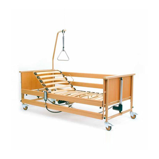
- Page 2 1 = head board (wooden sections) 2 = side guard 3 = handset 4 = release buttons for side guards 5 = foot 6 = castor 7 = mains cable holder 8 = location (both sides) of sleeves for patient’s lifting pole at mattress base frame Page 2 of 46...
- Page 3 Contents Foreword ........................5 General Information .....................6 Definition of the Groups of Persons Involved ..........Safety Information ................... 2.2.1 Explanation Safety Symbols Used ..........2.2.2 Safety Information Operator ............2.2.3 Safety Information User ..............Product Description ..................2.3.1 Designated ..................2.3.2 Special Features ..................
-
Page 4: Table Of Contents
Dismantling ..................... Storage Dolly ....................Operation......................26 Special Safety Information for the Drive Unit System ....... Handset ......................4.2.1 Using Handset ..................Handset with Blocking Function (Accessory) ..........4.3.1 Blocking function ..................4.3.2 Using handset ..................Castors ......................Mains Cable Holder .................. - Page 5 Dear Customer, BURMEIER would like to thank you for the confidence you have placed in us and our products in deciding to purchase this Arminia II nursing bed. Each bed has been tested by the manufacturer for electrical safety and functionality and has left our factory in perfect condition.
- Page 6 Medizinproduktegesetz (German abbreviation: MPG § 13, Medical Products Act). The nursing bed ARMINIA II has been inspected by TÜV (German abbreviation for Technischer Überwachungsverein, Technical Inspection Authority). Any piece of technical equipment, electrical or otherwise, can prove hazardous if not properly operated.
- Page 7 obligated to instruct users in the proper use of this nursing bed in accordance with MPBetreibV § 5 (Operators of Medical Products Ordinance). • Ensure that users know where this instruction manual is located in accordance with MPBetreibV § 9 (Operators of Medical Products Ordinance).
- Page 8 TÜV inspected (German abbreviation for Technischer Überwachungsverein, Technical Inspection Authority). • Use the ARMINIA II Nursing Bed only if you are absolutely certain that it is in perfect working order. The most important objective of the safety information is to prevent personal injuries.
- Page 9 (fire hazard in the presence of penetrating fluids). o chapter 2.3.1 of this instruction manual. In the case of ambiguity, consult the manufacturer of the additional equipment or BURMEIER. • Check that your staff are complying with the safety information.
- Page 10 2.2.3 Safety Information for the User • Ensure that the operator instructs you in the safe operation of this bed. • Each time before using the nursing bed, check that it is in perfect working order. • Ensure that no obstacles such as furniture or sloped ceilings could impede adjustments to the bed.
- Page 11 Page 11 of 46...
- Page 12 2.3 PRODUCT DESCRIPTION 2.3.1 Designated Use • The ARMINIA II Nursing Bed, hereafter referred to as the bed, was developed as a comfortable solution for the home care of infirm or disabled persons in need of care. It should support this care.
- Page 13 regulations. 2.3.2 Special Features Electrical height adjustment of the mattress base between approx. 40 and 80 cm. Electrical adjustment of the backrest between 0° and approx. 70°. Electrical adjustment of the thigh rest between 0° and approx. 35°. Electrical tilting of the mattress base into the prone position to approx.10°.
- Page 14 mechanism is secure and can only be released when the side guard is slightly lifted. Electrical Adjustment System The electrical drive system for this bed is fault-secure, flame-retardant (V0) and consists of: the electronic control unit. The control unit generates, via a transformer, a 24 Volt protective low voltage which is non- hazardous for patients and users.
- Page 15 - Upon delivery the bed is packed or mounted on a storage dolly. The operator’s experts assemble the bed on site. The assembly should be carried out by two people. • Remove all packaging materials and cable bindings. Packing units Box 1: mattress base complete with electrical motors 4 side guard bars patient's lifting pole with grab handle...
- Page 16 3.1.1 Assembly of the Mattress Base • Remove the side guards and patient’s lifting pole from the storage dolly. (see chapter 3.5). These parts will be assembled later. • Remove both mattress base parts from the storage dolly. • Rest the head section of the mattress base on end on the floor;...
- Page 17 3.1.2 Assembly of the bed • Lay the mattress base frame flat on the floor. • Unscrew the knurled screws at the head of the bed. • Raise the mattress base frame at the head end of the bed. Slide the connecting piece on the headboard into the mattress base frame until the mattress base frame is adjacent to the...
- Page 18 • Attach the head boards to the head and foot sections one after the other and press them down as far as they will go. • Use the Spax screws to fasten the head boards through the catch. Page 18 of 46...
- Page 19 3.1.3 Assembly of the Side Guards At all four bed corners there is a guide rail in the head/foot boards for the side guards. • Slip one plastic slider upwards into each guide rail of the head section. • The plastic sliders must always be inserted into the guide rails such that their pointed ends point upwards.
- Page 20 • Insert another plastic slider (tip pointing upwards) into the other end of the bars. Press the lower release button and move the plastic slider up in the guide rail of the footboard. • Assemble the second side guard in the same manner.
- Page 21 3.2.1 Plug Assignment of the Control Unit 1 backrest motor 2 thigh rest motor 3 total height 4 foot end height motor HB handset 3.3 PUTTING INTO SERVICE Each time, before putting the bed into service, the user must check that: -the bed castors are braked (see chapter 4.4).
- Page 22 3.3.1 Strain Relief The strain relief for the mains cable is located under the middle of the mattress base frame. • Check that the strain relief is securely fastened and is operating effective Page 22 of 46...
- Page 23 If you have any questions or concerns, consult the manufacturer of the additional equipment or BURMEIER. Observe the following points when positioning the bed in order to minimise, as much as possible, the risk of fire due to external influences.
-
Page 24: Dismantling
3.3.3 Operational Readiness • After the bed has been assembled, carry out an inspection in accordance with chapter 6.2 . • Clean and disinfect the bed prior to first-time use and before reusing in accordance with chapter 5. After all the steps in chapter 3.1 to 3.3.3 have been successfully carried out and observed, the bed is considered operational. -
Page 25: Storage Dolly
3.5 STORAGE DOLLY If the bed has a storage dolly, it can be mounted on it by following the instructions given below. connection piece. The mattress handles must point inwards. The side of the foot board has to point downwards to prevent the thigh rest from tipping. -
Page 26: Special Safety Information For The Drive Unit System
4.1 S PECIAL AFETY NFORMATION FOR THE RIVE YSTEM When making any adjustments, ensure that no limbs from the patient, user or other persons, especially playing children, are under the rests or the bed frame. Otherwise, this could lead to trapped or injured limbs. To safeguard the patient against unintentional motorised adjustments, always block electrical handset adjustments of the back and thigh rests on electrical beds when the side guards are raised (risk of limbs being... -
Page 27: Handset
backrest mattress base height thigh rest prone position 4.2 HANDSET The electrical bed functions can be activated by the patient or the user using the handset. o The electric motors operate as long as the corresponding buttons are pressed. o All adjustments, with the exception of the prone position, are possible in both... -
Page 28: Using The Handset
4.2.1 Using the Handset Adjusting the backrest By pressing these keys, the adjustment angle of the backrest can be altered. Adjusting the mattress base height By pressing these keys, the height of the mattress base can be altered. When adjusting the height of a mattress base which has been tilted in the prone position, the bed is automatically set to the horizontal position at its highest or lowest position. -
Page 29: Handset With Blocking Function (Accessory)
backrest mattress base height 4.3 HANDSET WITH BLOCKING FUNCTION (ACCESSORY) thigh rest The electrical bed functions can be activated by the patient or the user using the handset. For safety reasons, a blocking function is incorporated in the handset. Depending on the clinical condition of prone position the patient, the user can block handset adjustments when deemed necessary by the supervising doctor. -
Page 30: Blocking Function
lower 4.3.1 Blocking function Upon delivery of the bed, a blocking key is fastened to the handset with a cable binding. The blocking key is not intended for use by the patient and must be removed from the handset. The blocking key should remain with the user for safekeeping. -
Page 31: Using The Handset
blocking surface using the blocking key into the desired position. The display colour will change accordingly (see below). Respective drive blocked: Vertical blocking surface; Display colour: yellow The blocked buttons cannot be activated Respective drive released: Blocking surface rotated approx. 15° clockwise Display colour: green The unblocked buttons can be... -
Page 32: Castors
Setting the prone position By pressing these keys, the mattress base can be adjusted to a prone position. Only the "lower" key is active. When adjusting the height of a mattress base which has been tilted in the prone position, the bed is automatically set to the horizontal position at its highest or lowest position. -
Page 33: Mains Cable Holder
Release: Use your foot to push the release switch towards the bed leg. Locking: Use your foot to press down on the foot lever. 4.5 MAINS CABLE HOLDER The mains cable holder is located on the side of the mattress base frame near the foot section. -
Page 34: Lower Leg Rest
There are two location sleeves (a) for a patient’s lifting pole found at both corners on the inside of the mattress base frame at the head end of the bed. Each sleeve has a recess (c) on the upper surface. The patient’s lifting pole should be inserted on the side of bed where the patient gets in and out. -
Page 35: Side Guards
• Raise the lower leg rest by the frame - and not by the mattress handles - until the desired position is reached. The lower leg rest will automatically lock in place. Lowering When the thigh rest is lowered using the handset, the lower leg rest is automatically lowered as well. - Page 36 Page 36 of 46...
- Page 37 Page 37 of 46...
-
Page 38: Emergency Lowering Of The Backrest
4.9 EMERGENCY LOWERING OF THE BACKREST In the event of power supply outages or electrical drive system failures, the raised backrest can be lowered by hand. In this case, two people are absolutely necessary! As a precautionary measure, recommend that emergency lowering of the backrest be practiced... - Page 39 5.1 GENERAL INFORMATION Cleaning is the most important measure and requirement for a successful chemical disinfection. When the bed is occupied by the same patient, routine cleaning of the bed is generally sufficient to ensure a hygienic environment. Disinfection of the undercarriage is only necessary when it has been visibly contaminated with infectious or potentially infectious materials (blood, stool, pus) or, if in the presence of an infectious disease, under doctor’s orders.
-
Page 40: Cleaning And Disinfection Instructions
5.2 CLEANING AND DISINFECTION INSTRUCTIONS • Remove bed linens and send them to the laundry service. • Clean all surfaces including the slatted bed frame and mattress base made from synthetic inserts or wire netting with a mild and environmentally friendly cleaning agent. -
Page 41: Cleaning And Disinfection Agents
• Despite the excellent mechanical resistance of the bed, scratches, markings, etc. which permeate the entire coating should be resealed using a suitable medium to prevent the penetration of moisture. For further information, consult BURMEIER or a specialist of your choice. Page 41 of 46... -
Page 42: Handling Disinfection Agents
Note: As a rule, aldehyde-based disinfection media have the advantage that they have a wide spectrum of impact, a relatively low protein effect and are environmentally friendly. The main disadvantage of these agents is their potential to cause allergies and irritation. Glucoprotamine-based formulations do not have this disadvantage and are equally effective although most are somewhat more expensive. -
Page 43: By The User
Legal Principles In accordance with - Medizinprodukte-Betreiberverordnung § 4 (Operator’s Ordinance on Medical Products, Maintenance) - Berufsgenossenschafts-Vorschrift BGV A2 (Directive of the German Employers Liability Insurance Association, previously VGB 4, Testing of mobile electrical equipment in industrial use) operators of nursing beds are obligated to keep medical products in a safe state throughout their entire service life. - Page 44 Check List: Inspection by the User Check Description of Defect Visual Inspection of the Electrical Components Handset, handset cable Damage, routing Mains cable Damage, routing Damage, plastic Handset covering Visual Inspection of the Mechanical Components Damage, Patient's lifting pole, location sleeves deformations Damage, Undercarriage...
-
Page 45: By The Operator
6.2 BY THE OPERATOR In order to guarantee the safe state of this nursing bed, the operator of this nursing bed is obligated to carry out regular inspections each time the bed is reassembled or maintained and when the bed is in continuous operation (in accordance with the MPBetreibV §... -
Page 46: Trouble-Shooting
Trouble-shooting Table The following table is a guide for detecting and rectifying malfunctions: Problem Possible causes Solution Handset or drive • Mains cable is not • Insert mains cable unit system is not plugged in • No power • Check socket/fuse box functioning supply to socket •...
Need help?
Do you have a question about the ARMINIA II and is the answer not in the manual?
Questions and answers