
Subscribe to Our Youtube Channel
Related Manuals for burmeier Dali


Summary of Contents for burmeier Dali
- Page 1 Dali Instruction Manual Part A: General Information Part B: Operator and Technical Personnel Part C: Care staff and residents 2022-01-07 | Version 05 | 272846 REF: 221234...
- Page 2 Part A: General Information...
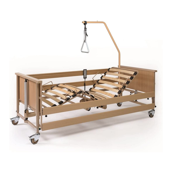
- Page 3 [1] Foot end chassis [2] Safety side release buttons (4x) [3] Lower leg rest [4] Thigh rest [5] Handset [6] Triangular grab handle [7] Backrest [8] Patient lifting pole [9] Head end chassis [10] Mattress retainers (4x) [11] Guide rails (4x) [12] Lifting pole sleeves (2x) [13] Castors (4x) [14] Control unit (concealed in the pic-...
-
Page 5: Table Of Contents
Dimensions and weights.....................11 4.5.5 Adjustment ranges......................12 4.5.6 Ambient conditions......................12 4.5.7 Classification........................13 4.5.8 Electrical data: Dali standard, low-entry................14 4.5.9 Electrical data: Dali econ, low-econ, low-entry-econ............16 4.5.10 Electrical data: Dali wash....................18 4.5.11 Information on electromagnetic compatibility (EMC)............20... -
Page 7: Part A: General Information
Address, information for custom- ers, market note Manufacturer Burmeier GmbH & Co. KG (A Stiegelmeyer-Group company) Industriestraße 53 / 32120 Hiddenhausen / Germany Tel.:+49 (0) 5223 9769 - 0 Fax:+49 (0) 5223 9769 - 090 Email:info@burmeier.com Internet:www.burmeier.com Service centre To order replacement parts in Germany and for any servicing requirements or other ques- tions, please contact our service centre: Burmeier GmbH &... -
Page 8: Foreword
Foreword Dear Customer, Burmeier has built this bed to give you the best possible help with the challenges of care in the home. We passionately pursue the goal of developing products that are durable and of a high-quality. Our products should make residents feel as safe and comfortable as possible during their stay in bed and also lighten the workload of care staff and caring relatives. -
Page 9: Conventions Of This Instruction Manual
Conventions of this Instruction Manual Safety Information At the time of delivery, the Dali care bed represents state-of-the-art technology and has been tested by an independent testing institute. Only use the Dali care bed if it is in perfect working order. -
Page 10: Icon Information
Conventions of this Instruction Manual The safety symbols used are not a substitute for the written safety information. It is important therefore to read the safety information and follow the instructions exactly! Icon Information General information and cross-references will be displayed in the following way: General information, tips and helpful courses of action. -
Page 11: Product Description
It it designed to support this care. • The use of the Dali care bed in hospitals is only permitted in rooms designed for medi- cal treatment of the application group 0. •... -
Page 12: Contraindications
Product Description Weight of accessories Maximum permitted weight of resident (incl. mattress) Dali (standard, low-econ, econ, Dali low-entry, Dali wash) low-entry-econ 10 kg 175 kg 165 kg 20 kg 165 kg 155 kg • Please refer to the safety information provided in the chapter Part B: Safety Informa- »... -
Page 13: Components Of The Bed
Product Description CAUTION Risk of injury Failure to heed this warning may result in physical injury to the resident due to entrapment or crushing of limbs. • Owing to the smaller limbs of residents with a body height/weight that is less than this, there is an increased risk of entrapment between the open spaces of the safety sides when safety side systems are used. -
Page 14: Mattress Base Sizes
The user can lock the adjustment options on the handset if the poor clinical condition of the resident necessitates this. • A cabled handset with a sturdy hook, for Dali Standard and Dali low entry The user can lock the adjustment options on the handset if the poor clinical condition of the resident necessitates this. -
Page 15: Technical Data
Product Description Mattress base dimensions (WxL) External dimensions (WxL) 90 x 200 cm (wooden or metal mattress base) 102 x 218 cm Technical Data 4.5.1 Type plate You can find the type plate on the bed frame at the head end. The type plate contains the following information: Type plate, example Type plate (electrical data), example... - Page 16 Product Description Explanation of the graphical symbols used: Protection Class II device, shock-proof Only for use in enclosed spaces – do not use outdoors Dispose of electrical components in accordance with the WEEE Direc- tive. Do not dispose of as household waste! Attention! Follow the operating instructions Total weight of the bed Protection of electrical equipment from water splashing from any direc-...
-
Page 17: Pid Number
Product Description 4.5.2 PID Number Relevant order information is summarised for the manufacturer under the PID number. Have the PID number ready any time you contact your specialist dealer. You can find the PID no. on the bed frame at the head end. Part Image1: PID Number... -
Page 18: Adjustment Ranges
Product Description Bed model standard/econ wash low-entry, low- entry-econ/low- econ Chassis with motors 34 kg Wooden mattress base 37 kg 37 kg frame with motors Metal mattress base 41 kg frame with motors 4 wooden safety side 13 kg bars 4 metal safety side bars 17.5 kg Patient lifting pole... -
Page 19: Classification
Product Description Storage temperature min. -10°C, max.+50°C Relative humidity Min. 20 %, max. 80 % (not condensed) Air pressure (at altitude ≤ 3000 Min. 700 hPa, max. 1060 hPa In operation: Ambient temperature min. + 5°C max. + 40°C Relative humidity Min. -
Page 20: Electrical Data: Dali Standard, Low-Entry
(e.g. retirement and nursing homes, rehabilitation facilities and geriatric in- stitutions) Care in the home. A medical electrical device is used to alleviate or compensate for injuries, disabilities or illnesses. 4.5.8 Electrical data: Dali standard, low-entry Control unit Type: CBSTI01-V2 Type: CBSTI01-V3 Compatible with:... - Page 21 Product Description Switch mode power supply Type SMPS12 Output current 4.5 A Duty cycle Intermittent duty: 2 min ON / 18 min OFF Protection category IPX4 Classification Protection class 2 Handset with locking function Bluetooth handset Cabled handset Type HBSTI HL74 Protection category IPX6...
-
Page 22: Electrical Data: Dali Econ, Low-Econ, Low-Entry-Econ
Duty cycle 2 min ON / 18 min OFF Electric motor noise level Noise level during adjustments < 50 dB (A) 4.5.9 Electrical data: Dali econ, low-econ, low-entry-econ Control unit Type: CA 20 Compatible with: Cabled handset Operating voltage 120 - 240 VAC, 50/60 Hz Current input 1.5 A... - Page 23 Product Description Electric motor for mattress base height Type Linak LA 24 Force/lift 1400 N / 405 mm Input voltage DC 24 V Protection category IP X4 Duty cycle 2 min ON / 18 min OFF Electric motor for backrest Type Linak LA 24 Force/lift...
-
Page 24: Electrical Data: Dali Wash
Product Description 4.5.10 Electrical data: Dali wash Control unit Type: CBSTI01-V2 Compatible with: Bluetooth and cabled handset Operating voltage Through SMPS 12-type external power supply unit Output current Duty cycle Intermittent duty: 2 min ON / 18 min OFF Protection category... - Page 25 Product Description Handset with locking function Bluetooth handset Cabled handset Type HBSTI HL74 Protection category IPX6 IPX4 Electric motor for mattress base height Type Linak LA 27 Force/lift 1400 N / 405 mm Input voltage DC 24 V Protection category IP X6 Duty cycle 2 min ON / 18 min OFF...
-
Page 26: Information On Electromagnetic Compatibility (Emc)
Failure to heed this warning may result in malfunctions and material damage. • The use of accessories, transducers and cables other than those supplied by BURMEIER for this bed may result in increased electromagnetic emissions or reduced electromagnet- ic immunity of the bed and may lead to incorrect operation. - Page 27 Product Description Sheathing Phenomenon EMC basic standard Immunity level (test + compli- or test method ance) Home healthcare environment Electrostatic discharge (ESD) IEC 61000-4-2 +/- 8 kV contact +/- 2 kV, +/- 4 kV¸ +/- 8 kV, +/- 15 kV; +/- 25 kV air High-frequency electromagnetic IEC 61000-4-3...
- Page 28 Product Description Ports for signal input/signal output parts Phenomenon EMC basic standard Immunity level (test + compli- ance) Home healthcare environment Electrostatic discharge (ESD) IEC 61000-4-2 +/- 8 kV; contact +/- 2 kV, +/- 4 kV¸ +/- 8 kV, +/- 15 kV; +/- 25kV air;...
- Page 29 Product Description Table zz: Test specifications for the immunity of sheathings to high-frequency wire- less communication equipment Test fre- Frequen- Radio serv- Modulation Max. Distance Immunity quency cy band power W test level GSM 1900, 1845 DECT, LTE band 1; 3; 4; 1970 25;...
- Page 30 Part B: Operator and Technical Per- sonnel...
- Page 31 [1] Foot end chassis [2] Safety side release buttons (4x) [3] Lower leg rest [4] Thigh rest [5] Handset [6] Triangular grab handle [7] Backrest [8] Patient lifting pole [9] Head end chassis [10] Mattress retainers (4x) [11] Guide rails (4x) [12] Lifting pole sleeves (2x) [13] Castors (4x) [14] Control unit (concealed in the pic-...
- Page 33 Contents Part B: Operator and Technical Personnel Target Groups, Qualifications and Duties..............1 Operators............................1 1.1.1 Responsibilities of the Operator................... 1 Technical Personnel.........................2 Safety Information......................3 General information......................... 3 Safety Information for Operating the Bed..................3 2.2.1 Electrical Cables and Connections..................4 2.2.2 Operating Time of Electric Drives..................5 2.2.3...
- Page 34 3.7.1 Plug assignment (CBSTI01-V2 and CBSTI01-V3)............. 21 3.7.2 Plug assignment (CA 20)....................22 3.7.3 Connector Assignment (Dali econ/CA 40)................22 Putting into Service...................... 24 Switch mode power supply connection..................24 Pairing the Bluetooth Handset...................... 25 Making Ready for Operation......................25 Cleaning and Disinfection....................26 Safety Information on Cleaning and Disinfection...............
- Page 35 Mount the dismantled bed on the storage aid................47 Disposal.........................49 10.1 Disposal of the Bed........................49 10.2 Disposal of Packaging........................49 10.3 Disposal of Electrical Components....................49 Appendix........................50 11.1 Accessories............................ 50 11.1.1 Mattress requirements......................50 11.1.2 Safety Side Requirements....................51 11.2 Translation of EC Declaration of Conformity................51...
-
Page 37: Target Groups, Qualifications And Duties
Operators (e.g.: medical equipment retailers, specialist dealers, health insurance) are all nat- ural or legal persons who use the Dali care bed or on whose behalf it is used. It is a require- ment that the operator duly instructs care staff in its use. -
Page 38: Technical Personnel
Target Groups, Qualifications and Duties Technical Personnel Technical personnel comprises persons who, based on their training or briefing, are qualified to deliver the care bed, assemble or dismantle it and to transport the bed. Furthermore, this personnel is briefed in the cleaning and disinfection instructions. Part B: Operator and Technical Personnel... -
Page 39: Safety Information
This instruction manual contains safety information which must be followed. All per- sons who work on or with the Dali care bed must be familiar with the contents of this instruction manual and must follow the safety information. -
Page 40: Electrical Cables And Connections
Safety Information 2.2.1 Electrical Cables and Connections WARNING Danger of electric shock Damaged mains cables can cause fatal electric shocks. Take the following measures to pre- vent hazards due to electric shock and malfunctions. • If a damaged mains cable continues to be used, this can lead to electric shock, fire and other hazards as well as malfunctions. -
Page 41: Operating Time Of Electric Drives
Safety Information 2.2.2 Operating Time of Electric Drives Continuous operation must not exceed two minutes! After this time, a rest period of at least 18 minutes must be observed. If the electric drive is operated for a much longer pe- riod, e.g. -
Page 42: Bluetooth Handset
Safety Information • When making any adjustments, always ensure that no limbs belonging to the resident, care staff or other persons, especially playing children, could be trapped underneath the rests or the mattress base during the adjustment. • Do not leave children unsupervised in the room with the bed. •... -
Page 43: Power Pack
Safety Information 2.2.5 Power Pack ATTENTION Working environment Failure to follow this can lead to system malfunctions or material damages! • After transport/storage in a cold environment, the power pack should not be operated until it has reached room temperature. 2.2.6 Bed Adjustment ATTENTION... -
Page 44: Special Hazards
Safety Information ATTENTION Damage to the bed / objects If the bed continues to be misaligned (ramped up) in the adjustment path due to overloading or obstacles (e.g. window sills), this may cause damage to the bed or other objects since the drive system does not have an electronic overload shut-off. -
Page 45: Batteries
Safety Information • Ensure that this equipment is used only for the purpose intended. • Ensure that this equipment is not inadvertently placed on or under the bedding (danger of overheating)! Use only LED bulbs, as far as possible, since these generate far less heat than conventional or halogen light bulbs. -
Page 46: Safety Information For Accessories
• Efficient and safe operation combined with maximum protection of residents can only be guaranteed if original Burmeier accessories designed for the relevant model of bed are used! Safety Information for Disposal... -
Page 47: Assembling The Care Bed
This chapter is intended to be read by professionals employed by the operator or by medical supply retailers. • Helpful assembly videos for setting up the bed can be found on www.burmeier.com/de/information/downloads or directly on YouTube. Please scan the following QR code with your mobile device: Tools An assembly key is supplied. -
Page 48: Included In The Package
Before using the bed on parquet flooring, check whether the castors will leave stains on the parquet varnish. The bed can be used on tiles, carpet, linoleum or laminate flooring without causing any damage. BURMEIER is not liable for any damage caused by day- to-day operation on floors. -
Page 49: Mattress Base Frame
Assembling the Care Bed Mattress base frame Proceed as follows to assemble the mattress base frame on the chassis: Remove the safety side bars and the patient lifting pole from the storage aid and set them aside for the time being. Remove the two halves of the mattress base frame from the storage aid. -
Page 50: Safety Side
Assembling the Care Bed Adhesive label on the head end chassis Adhesive label on the foot end chassis Proceed as follows to attach the chassis to the mattress base frame: Loosen both knurled-head bolts which are located adjacent to the two lifting pole adapt- er sleeves lower down in the mattress base frame. - Page 51 Assembling the Care Bed ATTENTION Risk of injury Failure to heed these warnings may result in injury and damage to property due to improp- erly assembled, falling safety side bars. • After installing each safety side bar, check that it is correctly locked into the holding devi- ces.
- Page 52 Assembling the Care Bed • Insert one end of the bar into the lower holding fixture (at the head end). • Insert the other end of the bar into the lower holding fixture (at the foot end). • The bar must firmly click into place with the aid of the release button [b]. •...
-
Page 53: Electrical Connection
Note:There is a strain relief for the 24 volt connection socket on the cross tube of the head end chassis (see [a]). The strain relief is provided with an angular open lug and applies for the Dali standard, Dali-wash and Dali low-entry bed variants. Part B: Operator and Technical Personnel... - Page 54 Assembling the Care Bed The connection socket is ready-fitted in the factory and is equipped with a pull-out pre- vention device [1] for the 6-pin plug of the switch mode power supply. • Pull up the pull-out prevention device [1] to release the retaining element. •...
- Page 55 Assembling the Care Bed • Insert the 6-pole plug [3] for the switch mode power supply into the mains socket. Attention - incorrect connection!If the plug-in power supply unit is incorrectly connected to the connection socket, the system cannot be operated. The IPX4 protection class cannot be guaranteed.
- Page 56 Please note:The 230 volt cable is ready-installed in the factory and fixed in place un- der the mattress base frame. • Simply insert the power plug into the electrical socket. Attention: The following instructions apply only for Dali low-entry and Dali low-entry-econ: Incorrect cable routing! The connecting cable is sub- jected to bending stress caused by the movement of the mattress base.
-
Page 57: Plug Assignment (Cbsti01-V2 And Cbsti01-V3)
Assembling the Care Bed Correct cable routing! The connecting cable is rout- ed from below over the “rear” side of the housing and then plugged in. The plug must be secured in place with the pull- out protection. 3.7.1 Plug assignment (CBSTI01-V2 and CBSTI01-V3) Plug assignment for drive system with Bluetooth/cabled handset Backrest motor Head end chassis lifting mo-... -
Page 58: Plug Assignment (Ca 20)
Be sure to compare the numbers on the ca- bles with the numbers on the lifting motors before connecting them. 3.7.3 Connector Assignment (Dali econ/CA 40) Connector assignment for drive system with cable handset Backrest motor... - Page 59 Assembling the Care Bed Please note: To avoid an incorrect connection of the lifting motors, the cables of the head- end and foot-end lifting motors are each provided with a number (2 for the head-end lift- ing motor and 4 for the foot-end lifting motor). These numbers can be found on the con- necting lines of the lifting motors accordingly.
-
Page 60: Putting Into Service
Putting into Service Switch mode power supply connection CAUTION Damage to switch mode power supply unit Failure to follow this information can result in irreparable faults to the switch mode power supply unit and a short-circuit in the wall socket. •... -
Page 61: Pairing The Bluetooth Handset
Putting into Service Pairing the Bluetooth Handset In the Dali standard, wash and low-entry. Before the bed functions can be adjusted, the handset must be coupled (connected) with the control unit. Proceed as follows: First remove the magnets from the handset to avoid any malfunction. -
Page 62: Cleaning And Disinfection
Cleaning and Disinfection Safety Information on Cleaning and Disinfection Cleaning is the most important measure and requirement for a successful chemical disinfec- tion. When the bed is occupied by the same resident, routine cleaning of the bed is generally suffi- cient. -
Page 63: Cleaning And Disinfection Plan
Cleaning and Disinfection • The electrical components must not be subjected to a jet of water, a high pressure cleaner or other similar devices! Clean only with a moist cloth (at most with pressure-less splash water)! • If you suspect that water or any other form of moisture has penetrated the electrical com- ponents, unplug the power plug immediately or do not plug it back into the socket. -
Page 64: Automated Cleaning (Dali Wash)
Cleaning and Disinfection 5.2.2 Automated Cleaning (Dali wash) To avoid adverse effects on the bed, it must be specially prepared for machine cleaning. The following steps are necessary to further guarantee the service life and functionality. • Move the care bed to the lowest position. -
Page 65: Cleaning Agents And Disinfectants
Cleaning and Disinfection ures required for cleaning and disinfection and should carry out the procedure in a reli- able manner (the operator should specify the operational procedures or the individual procedural steps). Care must be taken that only disinfection agents approved by the DGHM (German Society for Hygiene and Microbiology) are used, and that these are used only in the DGHM-approved concentrations. - Page 66 Cleaning and Disinfection • Ventilate the room after the disinfection has been completed. • Disinfect by wiping; do not disinfect by spraying! When spraying, a large portion of the disinfectant is released as spray and could be inhaled. • Furthermore, the wiping effect plays a significant role. •...
-
Page 67: Maintenance
Maintenance Legal principles Operators of medical beds in Europe are obliged, in accordance with the new Medical Device Regulation (EU) 2017/745 (MDR) and existing relevant national laws/regulations, e.g. in Ger- many currently the • German Medical Devices Operator Ordinance § 4 (Maintenance) •... -
Page 68: Inspections And Function Checks
Maintenance • Damage, defects and wear resulting from improper operation and after long-term use can- not be ruled out. • if they are not recognised and corrected immediately. To this end, there are legal requirements for conducting regular inspections in order to guar- antee the safe condition of this medical product. -
Page 69: Operating Current Test Procedure
BURMEIER offers leakage current testing of switch mode power supply units as a service. To take advantage of this, the switch mode power supply units must be sent to BURMEIER. You will receive tested switch mode power supply units in re- turn. Contact us for further details about this; refer to Part B: Replacement »... -
Page 70: Inspection Report
Unplug the 24-volt power supply cable from the socket. • Insert the plug of the 24-volt cable into the measuring adapter (special accessory, available from BURMEIER on request). • Connect the measuring adapter to the “test probe” or similar socket of the test de- vice. - Page 71 Location: Serial number: Application environment (IEC60601-2-52): [ ] 1 [ ] 2 [x] 3 [x] 4 [ ] 5 Manufacturer: Burmeier GmbH & Co. Applied parts: Mattress base, headboard, footboard, safety sides Testing equipment used (type/inven- tory no.): Medical Device Regulation classifica- tion: Class I I.
- Page 72 Maintenance Inspection report Visual inspection of the mechanical components Stickers and type plates Present, legible Patient lifting pole, adapter Damage, deformation sleeves Bed frame Damage, deformation Sprung slats Damage, splinters Castors Damage Mattress base Damage, deformation Wooden surround Damage, splinters Welded seams Split welded seams Safety side bars...
- Page 73 Maintenance Inspection report Result: Bed prot. ≥ 70 MΩ MΩ class II (type BF) Leakage current (direct or differential current measure- Description of de- ment) (type BF) fect Proceed as follows: Plug the mains cable/switch mode power supply into the test socket of the measuring instrument. Connect the probe of the measuring instrument to the bed;...
- Page 74 Maintenance Inspection report Handset: Operating function, lock- Perform the test acc. to ing function » Part C: Handset Motors Abnormal noise develop- ment (rattling, uneven run- ning) Strain relief of mains cable (if mains Mains cable firmly fas- cable available) tened Functional check of the mechanical components Joints and pivots...
-
Page 75: Replacement Parts
Expert: Replacement parts The relevant replacement parts are available from BURMEIER, by specifying the item num- ber, order number and serial number. You will find the necessary details by referring to the type plate and the PID number, which is located on the mattress base frame at the head end. - Page 76 Maintenance Burmeier GmbH & Co. KG (A Stiegelmeyer-Group company) Industriestraße 53, 32120 Hiddenhausen Tel.: +49 (0) 5223 9769 - 0 Fax: +49 (0) 5223 9769 - 090 Email: info@burmeier.com Part B: Operator and Technical Personnel...
-
Page 77: Replacement Of Electrical Components
Replacement of Electrical Compo- nents Safety Information WARNING Danger of death due to electric shock! • Before commencing any work on electrical equipment, always unplug the mains cable from the electrical socket! • Any work and/or repairs to the electrical equipment may only be carried out by the service engineers, the drive manufacturer or qualified and authorised electricians in compliance with all the relevant VDE and safety regulations! WARNING... -
Page 78: Replacing The Cabled Handset
Replacement of Electrical Components Replacing the cabled handset Control unit: CBSTI01V2 and CBSTI01V3 Control unit: CA 20 If possible, raise the bed to its highest position to make work easier. Disconnect the plug with the switch mode power supply unit from the socket. Open the cover of the control. -
Page 79: Replacing The Bluetooth Handset
Replacement of Electrical Components When inserting the plug, make sure that the recess is pointing upwards. Make sure that the O-ring seal on the plug is not damaged; otherwise, this plug connec- tion will not be protected from moisture. Close the cover of the control unit. •... - Page 80 Replacement of Electrical Components • Handsets must absolutely be kept away from babies and small children. • Do not leave babies and child alone near the bed. Please note: The handset is powered by a CR 2032 lithium battery. • Open the battery compartment cover [a] on the back of the handset.
-
Page 81: Troubleshooting
Troubleshooting Faults and their Rectification Simple faults and problems can often be rectified by trained care staff using the troubleshoot- » ing table in this instruction manual. Please refer to the Part C: Troubleshooting 29. In all other cases, the operator and/or the technical personnel for maintenance and repairs are re- sponsible for rectifying malfunctions and faulty components. -
Page 82: Dismantling The Care Bed
Dismantling the Care Bed Dismantling the care bed Proceed as follows to dismantle the care bed: Apply the brakes to the castors on the bed. Remove the patient lifting pole. Remove all the safety side bars, one after the other. •... -
Page 83: Dismantling The Mattress Base Frame
Dismantling the Care Bed In the case of econ, low-econ, low-entry-econ: Unscrew the power cable. Unplug the strain relief and plugs from the drive motors of the foot end and head end of the chassis. Loosen the knurled-thumb screws on the mattress base frame at the foot end to re- move the chassis foot section;... - Page 84 Dismantling the Care Bed • Secure the lifting bar of the drive motors against tipping using cable ties or something similar. • Tighten all knurled-thumb screws. • Insert the safety side bars into the basket between the two halves of the mattress base frame.
-
Page 85: Disposal
The operator of this bed is legally obliged to return the electrical components directly to the manufacturer and not to dispose of them at municipal waste collection points. Burmeier and its service and sales partners will take these components back. The return of these compo- nents is covered by our General Terms and Conditions. -
Page 86: Appendix
Appendix 11.1 Accessories The bed must only be operated with original BURMEIER accessories. BURMEIER does not accept any responsibility for accidents, defects and hazards that arise from the use of other accessories. WARNING Risk of hazard for residents due to improper use of accessories Pay attention to the following information when using safety sides, infusion stands, etc. -
Page 87: Safety Side Requirements
11.2 Translation of EC Declaration of Conformity We, Burmeier GmbH & Co. KG, in our sole responsibility as the manufacturer, hereby de- clare that this product complies with the provisions of REGULATION (EU) 2017/45 OF THE EUROPEAN PARLIAMENT AND THE COUNCIL of 5 April 2017 (MDR). - Page 88 Part C: Care staff and residents...
- Page 89 [1] Foot end chassis [2] Safety side release buttons (4x) [3] Lower leg rest [4] Thigh rest [5] Handset [6] Triangular grab handle [7] Backrest [8] Patient lifting pole [9] Head end chassis [10] Mattress retainers (4x) [11] Guide rails (4x) [12] Lifting pole sleeves (2x) [13] Castors (4x) [14] Control unit (concealed in the pic-...
- Page 91 Contents Part C: Care staff and residents Target Groups, Qualifications and Duties..............1 Care staff............................1 1.1.1 Duties of care staff....................... 1 Residents............................2 Safety Information......................3 Safety Information for Operating the Bed..................3 2.1.1 Electrical Cables and Connections..................3 2.1.2 Operating Time of Electric Drives..................4 2.1.3 Handset..........................
- Page 92 3.5.1 To Insert/Remove....................... 19 3.5.2 Slewing range........................20 Triangular Grab Handle........................20 3.6.1 Service Life.........................20 3.6.2 Adjusting the Grab Handle....................21 Safety side............................21 Lower Leg Rest..........................25 3.8.1 Raising Using the Handset....................25 3.8.2 Lowering Using the Handset....................25 3.8.3 Raising by hand (optional)....................25 3.8.4 Lowering by hand (optional)....................
-
Page 93: Target Groups, Qualifications And Duties
Care staff are persons who, based on their training, experience or briefing, are qualified to operate the Dali care bed on their own authority or to carry out work with the care bed, or have been instructed how to handle the care bed. Furthermore, they are able to recognise and avoid potential hazards and assess the clinical condition of the resident. -
Page 94: Residents
Target Groups, Qualifications and Duties • If any damage or malfunction is suspected, take the bed out of service. • Unplug the bed from the mains supply immediately. • Indicate clearly that the bed is "OUT OF ORDER". • Report this immediately to the operator responsible. A checklist for assessing the proper condition of the bed is given in the chapter Part C: »... -
Page 95: Safety Information
Safety Information Safety Information for Operating the Bed 2.1.1 Electrical Cables and Connections WARNING Danger of electric shock Damaged mains cables and/or power packs pose a potentially lethal hazard due to electric shock. Take the following measures to prevent hazards due to electric shock and malfunc- tions. -
Page 96: Operating Time Of Electric Drives
Safety Information • Do not place multiple socket bars under the bed. This could cause electrical hazards due to damaged mains cables or penetrating fluids. • Do not continue to use the bed if you suspect that the mains cable and/or power pack could be damaged. -
Page 97: Bluetooth Handset
Safety Information CAUTION Risk of injury Lock the operating functions for the resident on the handset if • The resident is unable to operate the bed safely, • The resident is unable to free himself or herself from potentially dangerous situations, •... -
Page 98: Bed Adjustment
Safety Information 2.1.5 Bed adjustment CAUTION Risk of injury Failure to heed this warning may result in physical injury due to entrapment or crushing! • When making any adjustments, always ensure that no limbs belonging to the resident, care staff or other persons, especially playing children, could become trapped underneath the mattress sections or the mattress base during the adjustment. -
Page 99: Safety Information For Attachments And Additional Equipment
2.2.1 Use of Resident Lifts CAUTION • Efficient and safe operation combined with maximum protection of residents can only be guaranteed if original Burmeier accessories designed for the relevant model of bed are used! CAUTION Risk of injury • Make sure that the attachment of accessories does not produce any crush or shearing zones for the resident when the bed sections are adjusted. -
Page 100: Safety Information For Accessories
Risk of injury • Efficient and safe operation combined with maximum protection of residents can only be guaranteed if original Burmeier accessories designed for the relevant model of bed are used! Safety information for users and residents Ensure that the operator/your medical supply store instructs you in the safe operation of this bed. -
Page 101: Operation
Operation Handset Depending on the equipment, the Dali care bed can be equipped with Bluetooth handset or cabled handset. All the electrical adjustment mechanisms on the bed can be controlled with the handset. The adjustment range for all functions is electrically/mechanically limited to the permitted ranges. -
Page 102: Bluetooth Handset
Operation Backrest Mattress base height Thigh rest Reverse-Trendelenburg posi- tion Magnetic sensor (identifiable by cross-hair symbol) Sleep position Battery symbol Locking symbol Adjust the mattress base height whenever necessary, but at least once a day, to the up- permost or lowest height. This automatically equalises the two independent adjustment drives and results in a level horizontal mattress base. -
Page 103: Cable Handset
Operation Adjusting the backrest This button can be used to change the backrest's level of ele- vation. Adjusting the mattress base height This button can be used to change the mattress base's height. Adjusting the thigh rest This button can be used to change the angle of the thigh rest. Reverse-Trendelenburg position: the mattress base can be tilted by up to approx. - Page 104 Operation • Only care staff are authorised to use the locking function! • If the clinical state of the resident is so critical that any adjustment using the handset pla- ces him/her at risk, then carers must lock this adjustment function immediately. The care bed remains in the position it was in at the time it was switched off.
- Page 105 Operation Unlock Function Lock Mattress base height Thigh rest Sleep position/reverse-Tren- delenburg position 3.1.3.2 Cabled handset ATTENTION Material damage Failure to heed this warning may result in damage to the handset. • Do not forcibly turn the locking key beyond the limit stop of the lock! The lock or the entire handset can be damaged.
-
Page 106: Operating Status Display Via Led
Operation • The locking key is not intended to be used by the resident. • The locking key must be removed from the handset. • Care staff or a person authorised by the doctor should take the locking key for safekeep- ing. -
Page 107: Led Power Pack
Operation 3.2.1 LED Power Pack LED colour State Duration Meaning yellow lights up permanently Enabling the voltage for the control unit. Functions can be per- formed green lights up permanently Power pack is in idle mode LED off does not light up Power pack is: •... -
Page 108: Led Bluetooth Handset
Operation 3.2.3 LED Bluetooth Handset LED colour State Duration Meaning yellow flashes 4x 0.5 s on/ 0.5 s off Battery low yellow lights up (when key is indicates that the func- pressed) tion is locked Castors WARNING Risk of injury Failure to heed this warning may result in injuries due to falling after the bed rolls away when getting into/out of bed, as well as to crushing. -
Page 109: Mains Cable Holder
Operation ATTENTION Material damage Failure to heed this warning may result in damage to the bed and to its surroundings. • Only move the bed around if the mattress base in adjusted to its lowest position. • Before moving the bed, always ensure that the switch mode power supply is placed safely on the bed to prevent it from falling off. -
Page 110: Patient Lifting Pole
Operation CAUTION Risk of injury • Hook the mains cable holder onto the headboard before moving the bed to prevent the mains cable from being driven over, crushed or torn off. This damage could lead to electri- cal hazards and malfunctions. Patient lifting pole WARNING Risk of injury... -
Page 111: To Insert/Remove
Operation There are two round lifting pole adapter sleeves at each corner of the head end [d] of the mattress base frame. There is a notch [a] on the top surface of the lifting pole adapter sleeve that, together with the pin [b], restricts the slewing range [c] of the patient lifting pole. The lifting pole should be fitted to the side of the bed that the resident uses to get in and out of bed. -
Page 112: Slewing Range
Operation 3.5.2 Slewing range Part Image2: Slewing range of patient lifting pole WARNING Risk of injury Failure to heed this warning may result in injury and damage to property due to the bed tip- ping up. • Only swivel the patient lifting pole within the slewing range of the bed [A]. •... -
Page 113: Adjusting The Grab Handle
Operation 3.6.2 Adjusting the Grab Handle Due to its adjustable belt, the grab handle height can be adjusted to between about 55 cm and 70 cm (measured from the upper edge of the mattress). Part Image3: Adjusting the Lifting Pole →... - Page 114 Operation WARNING Risk of injury Failure to heed this warning may result in physical injury due to the incorrect use of safety sides! • Only use technically perfect, undamaged safety sides which engage securely! • Use only the safety sides described in this manual. Safety sides are either factory integra- ted into the bed or available as accessories.
- Page 115 Operation Otherwise there is a danger of limbs being crushed or trapped by the safety sides if the resident inadvertently activates the handset. The effectiveness of the safety sides can also be reduced if any mattress base sections are raised to a high level. WARNING Risk of injury Failure to heed this warning may result in physical injury due to entrapment/suffocation.
- Page 116 Operation CAUTION Risk of injury Failure to heed this warning may result in physical injury to the resident due to the incorrect use of safety sides! • When making any adjustments with the safety sides and backrest raised, always ensure that no limbs of residents, care staff or other persons, especially playing children, could become trapped and injured underneath the rests and mattress sections or between the mattress retainer and the safety sides during the adjustment.
-
Page 117: Lower Leg Rest
Operation Repeat steps 2 and 3 at the other end of the bar. Lower Leg Rest 3.8.1 Raising Using the Handset If the thigh rest is raised using the handset, the lower leg rest is automatically lowered as well. 3.8.2 Lowering Using the Handset If the raised thigh rest is lowered using the handset, the lower leg rest locks into place in sev- eral intermediate positions. -
Page 118: Lowering By Hand (Optional)
Operation In order to raise the lower leg rest the thigh rest must also be raised. • Raise the lower leg rest at the foot end - not using the mattress retainer bars - until the desired position is reached. The lower leg rest engages automatically. 3.8.4 Lowering by hand (optional) WARNING... - Page 119 Operation WARNING Risk of injury If the backrest falls unchecked, the resident and/or the second member of staff could be injured! Manual CPR release of the backrest must be carried out by two people! In the event of power supply outages or electrical drive system failures, the raised backrest can be lowered by hand.
- Page 120 Operation Swing the lifting pipe up again, use the pin to secure it in place in the motor connector mount and fold the curved clip back over. Insert the pin again from the side of the thigh rest motor [c]. . Part C: Care staff and residents...
-
Page 121: Troubleshooting
Troubleshooting The following table is a guide to rectifying faults: If malfunctions occur while the bed is in use, and care staff are unable to remedy them with the aid of the troubleshooting table, the main- tenance and repair personnel of the bed operator concerned must be informed. WARNING Life-threatening danger, risk of injury Failure to follow this note can lead to fatal injuries. - Page 122 Troubleshooting Problem Possible causes Solution Drives only operate for a short • Too much weight on the → Reduce load time when buttons are pressed → Remove obstacle • Bed is blocked by an ob- → Reduce distance stacle • Distance from Bluetooth handset to control unit too Operation is not possible de-...
- Page 123 Troubleshooting Problem Possible causes Solution Electric backrest adjustments • Battery of the Bluetooth → Replace battery (see Part not possible handset empty B: Changing battery of » Bluetooth handset • Power cut → Use CPR release of the • Drives faulty backrest! •...
- Page 124 Troubleshooting Problem Possible causes Solution Switch mode power supply unit Short circuit in the supply line → Inform your operator if re- shuts down; pairs are necessary LED on the switch mode power supply unit is off despite the mains connection; LED on the switch mode power supply unit lights up yellow, even if no button is pressed...
-
Page 125: Maintenance
Maintenance As well as the extensive routine inspections performed by technical personnel, the bed must also be checked at shorter regular intervals by non-technical users (care staff, family carers etc.), and be briefly visually inspected and have its functions tested before being occupied by a new user. - Page 126 Maintenance Check Description of Fault What? How? Handset Damage, foil Switch mode power Damage, no rattling supply noises when shaken, cable routing Visual inspection of the mechanical components Lifting pole, handle Damage, deformation Bed frame Damage, deformation Sprung slats Damage, splinters Wooden surround Damage, splinters Mattress base frame...
-
Page 127: Cleaning And Disinfection
Maintenance Cleaning and Disinfection Cleaning – Private use ATTENTION Risk of material damage Failure to observe this can lead to material damage! • Unplug the power cable and store the power plug so that it does not come into excessive contact with water or other cleaning solutions (place in a plastic bag). - Page 128 The choice of cleaning agents and disinfectants available on the market may change from time to time. Burmeier therefore routinely tests the most commonly used materials for com- patibility. The most up-to-date list of tested cleaning agents and disinfectants can be obtained on request.
- Page 129 Cleaning and Disinfection Part C: Care staff and residents...
- Page 130 Cleaning and Disinfection Part C: Care staff and residents...
- Page 131 Cleaning and Disinfection Part C: Care staff and residents...
- Page 132 Burmeier GmbH & Co. KG Industriestraße 53 / D-32120 Hiddenhausen Telephone: +49 (0) 5223 9769 - 0 / Fax: +49 (0) 5223 9769 - 090 E-mail: info@burmeier.com www.burmeier.com...
Need help?
Do you have a question about the Dali and is the answer not in the manual?
Questions and answers