
Related Manuals for burmeier Regia


Summary of Contents for burmeier Regia
- Page 1 Regia Instruction Manual Part A: General Information Part B: Operator and Technical Personnel Part C: Care staff and residents 2021-12-14 | Version 03 | 278569 REF: 287900...
- Page 2 Part A: General Information...
- Page 3 Regia (Standard) care bed Regia care bed DSG (optional)
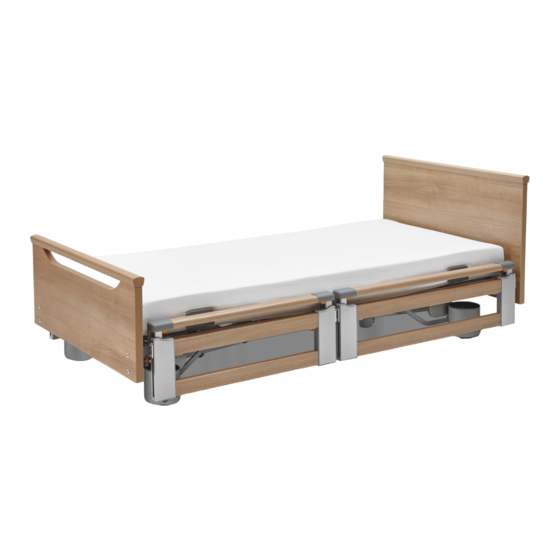
- Page 4 Regia care bed with telescopic safety sides (TSG) (optional equipment) [1] Footboard [2] Lower leg rest handle (both sides) / mattress retainer bar [3] Backrest handle (both sides) / [4] Adapter sleeves for patient lifting mattress retainer bar pole (head end) 2x...
-
Page 5: Table Of Contents
Contents Part A: General Information Address, Market Information..................1 Address, market information......................1 Foreword......................... 2 Conventions of this Instruction Manual............... 3 Safety information..........................3 Icon information..........................4 Product Description....................... 5 Use for the intended purpose......................5 Contraindications..........................6 Components of the Bed........................7 4.3.1 Mattress base frame......................7 4.3.2... -
Page 7: Part A: General Information
Address, Market Information Address, market information Manufacturer Burmeier GmbH & Co. KG (A Stiegelmeyer-Group company) Industriestraße 53 / 32120 Hiddenhausen / Germany Tel.:+49 (0) 5223 9769 - 0 • Fax:+49 (0) 5223 9769 - 090 Email:info@burmeier.com Internet:www.burmeier.com Service Centre To order replacement parts in Germany and for any servicing requirements or other ques- tions, please contact our service centre: Burmeier GmbH &... -
Page 8: Foreword
Even after you have purchased a bed, Burmeier is still on hand to help at any time. We pro- vide customised solutions in all matters relating to inspection and maintenance, repair and process optimisation. -
Page 9: Conventions Of This Instruction Manual
Conventions of this Instruction Manual Safety information At the time of delivery, the care bed Regia represents state-of-the-art technology and has been tested by an independent testing institute. Only use the care bed Regia if it is in perfect working order. -
Page 10: Icon Information
Conventions of this Instruction Manual The safety symbols used are not a substitute for the written safety information. It is important therefore to read the safety information and follow the instructions exactly! Icon information General information and cross-references will be displayed in the following way: General information, tips and helpful courses of action. -
Page 11: Product Description
Product Description Use for the intended purpose • This bed was developed as a comfortable solution for caring for persons in need of care or infirm persons in homes for the elderly, as well as in nursing homes. Further- more, it was developed as a supporting solution for home care, for infirm, disabled or frail persons. -
Page 12: Contraindications
Product Description Weight of accessories (incl. mattress) Maximum permitted resident weight 40 kg 185 kg • Please refer to the safety information provided in the chapter Part B: Safety Informa- » tion 3, especially in the case of residents in poor clinical condition. •... -
Page 13: Components Of The Bed
Product Description CAUTION Risk of injury Failure to heed this warning may result in physical injury to the resident due to entrapment or crushing of limbs. • Owing to the smaller limbs of residents with a body height/weight that is less than this, there is an increased risk of entrapment between the open spaces of the safety sides when safety side systems are used. -
Page 14: Optional Equipment
Product Description with protective low voltage using a connection cable. The socket available on the chas- sis is protected against the ingress of water. Electricity only flows from the external switch mode power supply unit to the bed while the handset is being used. •... -
Page 15: Mattress Base Sizes
Product Description Mattress Base Sizes The bed can be ordered in the following sizes. This instruction manual may describe functions or features that your model of bed does not have. Mattress base size External dimensions 90 x 200 cm (standard) 101 x 211 cm 100 x 200 cm (optional) 111 x 211 cm... - Page 16 Product Description Explanation of the graphical symbols used: Order number Date of manufacture (week/year) The article is a medical device Device with type BF applied part in accordance with IEC 601-1 (spe- cial protection against electric shock) Protection Class II device, shock-proof Only for use in enclosed spaces –...
-
Page 17: Pid Number
Product Description Explanation of the graphical symbols used: Permissible weight of patient Minimum resident measurements/weight: Height: 146 cm, weight: 40 kg; body mass index “BMI”: 17 Only use mattresses that are approved by the manufacturer. Lock the handset if the resident could be at risk due to inadvertent motorised adjustments. -
Page 18: Dimensions And Weights
» Part A: Mattress Base Sizes Note: Please refer to the dimensioned sketch on our website for further details: www.burmeier.com/de/information/downloads. Total weight, depending on model from approx. 118 kg to approx. 130 kg Safe working load... -
Page 19: Classification
Product Description Storage temperature min. -10°C, max.+50°C Relative humidity Min. 20 %, max. 80 % (not condensed) Air pressure (at altitude ≤ 3000 Min. 700 hPa, max. 1060 hPa In operation: Ambient temperature min. + 5°C max. + 40°C Relative humidity Min. -
Page 20: Electrical Data
Product Description procedures can be provided to help maintain or improve the condition of the resi- dent. (e.g. retirement and nursing homes, rehabilitation facilities and geriatric in- stitutions) Care in the home. A medical electrical device is used to alleviate or compensate for injuries, disabilities or illnesses. - Page 21 Product Description External switch mode power supply Classification Protection Class II, Type B, MDR classification Class I, not for use in explosive atmospheres External rechargeable battery (optional) Type Linak BA 18013 Voltage/capacity DC 24 V/ 1.2 Ah (lead-gel technolo- Max. charging current/ charging time 0.3 A/ 8-10 h Charging only admissible with Linak control units...
-
Page 22: Electrical Connection Diagram
Product Description Motors for mattress base height Duty cycle Intermittent duty: 2 min ON / 18 min Protection category IP X4 Backrest motor Type Linak LA 27 Force/installation dimension/lift 4000 N / 438 mm / 200 mm Input voltage Max. DC 34 V Duty cycle Intermittent duty: 2 min ON / 18 min Protection category... - Page 23 Product Description Part Image2: Location of the electrical components A: Head end, high up B: Centre of bed, high up C: Foot end, high up D: Head end, low down E: Centre of bed, low down F: Foot end, low down 4.5.9.1 Standard features The letters in the following tables refer to the previous picture “Location of the electrical...
- Page 24 Product Description 1: Backrest motor → B 2: Height adjustment motor at head end → E 3: Thigh rest motor → B 4: Height adjustment motor at foot end → E 5: Conventional handset → B 6: Control unit → A 4.5.9.2 Optional equipment Components with an asterisk must be inserted into the correct connection socket only.
- Page 25 Product Description 7: Distributor box (MJB5) → A 8: Under bed light → B 9: Rechargeable battery → A 10: Trendelenburg handset → B 11: Reading lamp → A 12: Distributor box (MJB8)→ A Part A: General Information...
-
Page 26: Information On Electromagnetic Compatibility (Emc)
Failure to heed this warning may result in malfunctions and material damage. • The use of accessories, transducers and cables other than those supplied by BURMEIER for this bed may result in increased electromagnetic emissions or reduced electromagnet- ic immunity of the bed and may lead to incorrect operation. - Page 27 Product Description Sheathing Phenomenon EMC basic standard Immunity level (test + compli- or test method ance) Home healthcare environment Electrostatic discharge (ESD) IEC 61000-4-2 +/- 8 kV contact +/- 2 kV, +/- 4 kV¸ +/- 8 kV, +/- 15 kV; +/- 25 kV air High-frequency electromagnetic IEC 61000-4-3...
- Page 28 Product Description Ports for signal input/signal output parts Phenomenon EMC basic standard Immunity level (test + compli- ance) Home healthcare environment Electrostatic discharge (ESD) IEC 61000-4-2 +/- 8 kV; contact +/- 2 kV, +/- 4 kV¸ +/- 8 kV, +/- 15 kV; +/- 25kV air;...
- Page 29 Product Description Table zz: Test specifications for the immunity of sheathings to high-frequency wire- less communication equipment Test fre- Frequen- Radio serv- Modulation Max. Distance Immunity quency cy band power W test level GSM 1900, 1845 DECT, LTE band 1; 3; 4; 1970 25;...
- Page 30 Part B: Operator and Technical Per- sonnel...
- Page 31 Regia (Standard) care bed Regia care bed DSG (optional)
- Page 32 Regia care bed with telescopic safety sides (TSG) (optional equipment) [1] Footboard [2] Lower leg rest handle (both sides) / mattress retainer bar [3] Backrest handle (both sides) / [4] Adapter sleeves for patient lifting mattress retainer bar pole (head end) 2x...
- Page 33 Contents Part B: Operator and Technical Personnel Target Groups, Qualifications and Duties..............1 Operator............................1 1.1.1 Responsibilities of the operator.................... 1 Technical Personnel.........................2 Safety Information......................3 General information......................... 3 Safety Information for Operating the Bed..................3 2.2.1 Electrical cables and connections..................4 2.2.2 Operating time of electric drives...................5 2.2.3...
- Page 34 3.6.1 No safety sides (standard)....................24 3.6.2 Full-length safety sides (DSG)................... 24 3.6.3 Split safety sides........................ 27 Adaptable bed extension (option)....................36 3.7.1 Installation (with split safety sides)..................36 3.7.2 Removal..........................37 Comfort mattress base (optional)....................38 Electrical connection........................39 Putting into Service...................... 41 Putting into service........................
- Page 35 Troubleshooting......................63 Faults and their rectification......................63 Decommissioning......................64 Dismantling the Care Bed.................... 65 Disposal.........................66 11.1 Disposal of the Bed........................66 11.2 Disposal of Packaging........................66 11.3 Disposal of Electrical Components....................66 Appendix........................67 12.1 Accessories............................ 67 12.1.1 Mattress requirements......................67 12.1.2 Safety Side Requirements....................68 12.2 Translation of EC Declaration of Conformity................68...
-
Page 37: Target Groups, Qualifications And Duties
If any other equipment is attached to the bed, (e.g. compressors for positioning systems, etc.), ensure that this is securely fastened and is functioning properly. If anything is unclear, please contact the manufacturer of the device, or Burmeier. Part B: Operator and Technical Personnel... -
Page 38: Technical Personnel
Target Groups, Qualifications and Duties Technical Personnel Technical personnel comprises persons who, based on their training or briefing, are qualified to deliver the care bed, assemble or dismantle it and to transport the bed. Furthermore, this personnel is briefed in the cleaning and disinfection instructions. Part B: Operator and Technical Personnel... -
Page 39: Safety Information
Safety Information General information Before using the care bed for the first time: • Read this instruction manual in full. This will help you to prevent injuring persons or damaging materials as a result of incorrect handling. • Please read and note the information on approved mattresses in accordance with the »... -
Page 40: Electrical Cables And Connections
Safety Information 2.2.1 Electrical cables and connections WARNING Risk of injury Failure to heed this warning may result in fatal injuries due to damaged mains power ca- bles. • Do not use damaged mains power cables! This can lead to electric shock, fire and other hazards as well as malfunctions. -
Page 41: Operating Time Of Electric Drives
Safety Information 2.2.2 Operating time of electric drives Continuous operation must not exceed two minutes! After this time, a rest period of at least 18 minutes must be observed. If the electric drive is operated for a much longer pe- riod, e.g. -
Page 42: Bed Adjustment
Safety Information • When making any adjustments, always ensure that no limbs belonging to the resident, care staff or other persons, especially playing children, could be trapped underneath the rests or the mattress base during the adjustment. • Do not leave children unsupervised in the room with the bed. •... -
Page 43: Special Hazards
Safety Information Special Hazards 2.3.1 Risk of fire WARNING Risk of injury Failure to heed this warning may result in a fire caused by various external factors. To pre- vent a fire, take the following precautionary measures. • Use only flame-retardant mattresses and bedding if possible. •... -
Page 44: Safety Information For Attachments And Additional Equipment
• Efficient and safe operation combined with maximum protection of residents can only be guaranteed if original Burmeier accessories designed for the relevant model of bed are used. Part B: Operator and Technical Personnel... -
Page 45: Safety Information For Disposal
Safety Information Safety information for disposal WARNING Risk of infection Failure to heed this warning may result in infections. Beds, bed components or accessories that have not been disinfected can become health hazards for people. • The operator must ensure that all components of the bed that are to be disposed of are not infectious or contaminated. -
Page 46: Assembling The Care Bed
• Helpful assembly videos for setting up the bed can be found on www.burmeier.com/de/information/downloads or directly on YouTube. Please scan the following QR code with your mobile device: Included in the package The bed is delivered unassembled. Two people are required to assemble the bed. -
Page 47: Location Requirements
Before using the bed on parquet flooring, check whether the castors will leave stains on the parquet varnish. The bed can be used on tiles, carpet, linoleum or laminate flooring without causing any damage. Burmeier is not liable for any floor damage that may be caused by day-to-day operation. - Page 48 Assembling the Care Bed The motors of the thigh rest and the back rest have been secured in transport position by the manufacturer. They must first be removed from their transport position. ⁃ Remove the locking pin on the housing. ⁃...
- Page 49 Assembling the Care Bed Put the mattress base in place. Note: Pay attention to the signs indicating the head and foot end. Insert the location pins [1] into the holes on both sides. Connect the mattress base and the chassis [2] with the handwheel bolts (2 x 2 bolts). Part B: Operator and Technical Personnel...
- Page 50 Assembling the Care Bed Raise the backrest by hand. Insert the backrest motor into the take-up and secure it in place with the locking pin [3] on the housing side. Note: Observe the following installation position. The housing assembly must be loca- ted over the lift motor.
-
Page 51: Headboard And Footboard
Assembling the Care Bed Raise the thigh rest. Place the thigh rest motor in the take-up. Secure the thigh rest motor in place on the housing side using the locking pin [5]. Note: Observe the following installation position. The housing assembly must be loca- ted over the lifting motor. -
Page 52: Attachment
Assembling the Care Bed • After assembly, carry out the mandatory checks to make sure that the fixings are secure. • To ensure that the plastic locking levers of the “Easy Switch” system function properly, do not allow them to fall or suffer severe knocks during disassembly or storage. •... -
Page 53: Removal
Assembling the Care Bed Swivel the locking levers [3] (left and Check that the headboard/footboard is right side) upwards and press until firmly in place by pulling the top edge they audibly click into place of the board to and fro 3.4.2 Removal Similar to illustration! -
Page 54: Side Panels
Assembling the Care Bed Use a finger to pull the orange safety Swivel the locking levers [2] (left and lock [1] towards the centre of the bed right side) downwards. and keep holding it in this position. Standing behind the headboard/foot- Pull the headboard/footboard straight board, firmly grip the uppermost cor- up and then outwards out of the slits in... - Page 55 Assembling the Care Bed • After assembly, carry out the mandatory checks to make sure that the fixings are secure. • To ensure that the plastic locking levers of the “Easy Switch” system function properly, do not allow them to fall or suffer severe knocks during disassembly or storage. •...
- Page 56 Assembling the Care Bed Swivel the locking levers [2] (left and right side) upwards and press until they audibly click into place. Check that the side panel is firmly in place by jiggling the top edge of the panel to and fro.
- Page 57 Assembling the Care Bed Swivel the locking levers [2] (left and right side) downwards. Grasp the lower edge of the side panel with both hands. Pull the side panel, as smoothly as possible, straight up and then outwards out of the slits in the tube.
-
Page 58: Full-Length Side Panels
Assembling the Care Bed 3.5.2 Full-length side panels The bed can optionally be fitted with full-length side panels (1x per bed side). The use of full- length side panels is only possible in conjunction with full-length safety sides (DSG). 3.5.2.1 Attachment The side panels are fixed to the longitudinal tube of the mattress base using screws. -
Page 59: Safety Sides
Assembling the Care Bed 3.5.2.2 Removal Proceed in reverse order to the attachment process. Safety sides WARNING Risk of injury Failure to heed this warning may result in physical injury due to falling from the bed. • Use only the safety sides described in this manual. Safety sides are either factory integra- ted into the bed or available as accessories. -
Page 60: No Safety Sides (Standard)
Assembling the Care Bed 3.6.1 No safety sides (standard) This bed is delivered as standard without any safety sides. 3.6.2 Full-length safety sides (DSG) The bed can be equipped with full-length safety sides at the customer’s request to protect the resident from accidentally falling out of bed. - Page 61 Assembling the Care Bed Insert one end of the bar into the lower holding fixture (at the head end). Insert the other end of the bar into the lower holding fixture (at the foot end). • The bar must firmly click into place with the aid of the release button [2]. •...
- Page 62 Assembling the Care Bed 3.6.2.2 Removal Position the safety side bars diagonally as shown. Press the release button [2] on the holding device down with your index finger and re- move one end of the bar. Part B: Operator and Technical Personnel...
-
Page 63: Split Safety Sides
Assembling the Care Bed Repeat step 2 at the other end of the bar Repeat steps 1 to 3 for the other safety side bars. 3.6.3 Split safety sides This care bed can also be fitted with optional “Easy Switch” split safety sides. WARNING Risk of injury Failure to heed these warnings may result in injuries due to entrapment or falls, as well as... - Page 64 Assembling the Care Bed • After assembly, carry out the mandatory checks to make sure that the fixings are secure. • To ensure that the plastic locking levers of the “Easy Switch” system function properly, do not allow them to fall or suffer severe knocks during disassembly or storage. •...
- Page 65 Assembling the Care Bed 3 Insert the locking hooks of the adapters in- to the slits in the long tube as far as they will go, and ensure that the safety side is inserted properly. 4 Swivel the locking levers (left and right- hand side) upwards and press them until they audibly click into place.
- Page 66 Assembling the Care Bed 3.6.3.2 Combination of split safety side and side panels WARNING Risk of injury Failure to heed these warnings may result in injury due to the unauthorised combined instal- lation of the split safety side (90 cm wide) and side panel (110 cm wide)! •...
- Page 67 Assembling the Care Bed Fig. D 3.6.3.3 Sticker – split safety sides (optional equipment) WARNING Risk of injury Failure to heed this warning may result in physical injury due to entrapment. • Please note: There is a sticker in the middle of the long side of the mattress base frame (see illustration).
- Page 68 Assembling the Care Bed With a bed extension The following is permitted: 2x size 110 cm split safety sides Bed extension approx. 20 cm Without bed extension Part B: Operator and Technical Personnel...
- Page 69 Assembling the Care Bed The following is permitted: 1 x size 90 cm split safety side 1 x size 110 cm split safety side 3.6.3.4 Covering cap – split safety side Please note: Slits are provided in the frame of the mattress base to accommodate split safety sides or side panels.
- Page 70 Assembling the Care Bed Removing the cover cap To remove or replace the cover cap, grasp it from below, push it down and remove it from the slit. Fitting the cover clip Proceed in reverse order to the removal proc- ess.
- Page 71 Assembling the Care Bed 3.6.3.5 Removal Use a finger to pull the orange safety lock [1] of the locking lever outwards and keep holding it in this position Tilt the locking levers (on the left and right-hand side) downwards Hold the safety side by grasping the housing sections at either side with both hands, as shown Part B: Operator and Technical Personnel...
-
Page 72: Adaptable Bed Extension (Option)
Assembling the Care Bed Pull the safety side straight up and then out of the slits in the long bed frame tube, as smoothly as possible Adaptable bed extension (option) The bed can be fitted with an extension at the foot end that extends the length of the mat- tress base by 20 cm. -
Page 73: Removal
Assembling the Care Bed Slightly raise the bed extension and push it forwards until the locking hooks on the bed extension slide over the cross tube on the mattress base frame and are positioned over the slits provided [A]. Press the bed extension down until the hooks snap into place. Swivel the locking levers upwards (on the left and right-hand side) and press them in until they audibly click into place »... -
Page 74: Comfort Mattress Base (Optional)
Assembling the Care Bed Comfort mattress base (optional) Regia can optionally be fitted with a comfort mattress base. The following assembly instruc- tions refer to the 90 cm and 100 cm wide mattress base: Included in the package: Wings of the black elements face out- wards [1]. -
Page 75: Electrical Connection
Assembling the Care Bed Electrical connection • When connecting components, always ensure that the plugs are inserted fully into the control unit. This is the only way to ensure proper sealing and faultless operation. • Ensure that the plug cover is always on the control unit. •... - Page 76 Assembling the Care Bed Proceed as follows: Plug the switch mode power supply into a mains socket. • The cable outlet must hang downwards (see picture). Insert the plug of the low-voltage cable into the connection socket found underneath the head end of the mattress base. Part B: Operator and Technical Personnel...
-
Page 77: Putting Into Service
Putting into Service Putting into service Before initial operation, no electrical measurement is necessary for beds with a 24-volt sys- tem, since these beds are tested for electrical safety and functionality by the manufacturer before they leave the factory in perfect condition. Making Ready for Operation •... -
Page 78: Cleaning And Disinfection
Cleaning and Disinfection Safety information on cleaning and disinfection Cleaning is the most important measure and requirement for ensuring successful chemical disinfection. When the bed is occupied by the same resident, routine cleaning of the bed is generally suffi- cient. Disinfection of the chassis is only necessary if it has been visibly contaminated with infec- tious or potentially infectious materials (blood, stool, pus etc.) or if the doctor requires this due to the presence of an infectious disease. -
Page 79: Cleaning And Disinfection Plan
Cleaning and Disinfection • Before operating the bed again, ensure that there is no residual moisture on the electrical contacts by drying or blowing on the power plug. • The electrical components must not be cleaned with a water jet, a high pressure cleaner or any other similar device! Clean only with a moist cloth (at most with pressure-less splash water)! •... -
Page 80: Cleaning Agents And Disinfectants
Cleaning and Disinfection • A clean bed must be transported in such a way that it will not become dirty or contami- nated during transport. • When dismantling the bed, we recommend that it should be cleaned and wiped down with disinfectant straight away. - Page 81 The choice of cleaning agents and disinfectants available on the market may change from time to time. Burmeier therefore routinely tests the most commonly used materials for com- patibility. The most up-to-date list of tested cleaning agents and disinfectants can be obtained on request.
-
Page 82: Handling Cleaning And Disinfection Agents
Cleaning and Disinfection Customers outside Germany can contact our distribution companies in their particular coun- try if they have any questions. Contact details can be found on our website. Handling Cleaning and Disinfection Agents • Follow the instructions for use for the particular products and their manufacturer. Pay attention to the exact dosage! We recommend the use of automated dosing instru- ments. -
Page 83: Maintenance
Maintenance Legal principles Operators of medical beds in Europe are obliged, in accordance with the new Medical Device Regulation (EU) 2017/745 (MDR) and existing relevant national laws/regulations, e.g. in Ger- many currently the • German Medical Devices Operator Ordinance § 4 (Maintenance) •... -
Page 84: Inspections And Function Checks
Maintenance • Damage, defects and wear resulting from improper operation and after long-term use can- not be ruled out. • if they are not recognised and corrected immediately. To this end, there are legal requirements for conducting regular inspections in order to guar- antee the safe condition of this medical product. -
Page 85: Operating Current Test Procedure
Burmeier offers leakage current testing of switch mode power supply units as a service. To take advantage of this, the power supply units must be sent to Burmeier. You will receive tested switch mode power supply units in return. Contact us for further details »... -
Page 86: Inspection Report
Location: Serial number: Application environment (IEC60601-2-52): [ ] 1 [ ] 2 [x] 3 [x] 4 [ ] 5 Manufacturer: Burmeier GmbH & Co. Applied parts: Mattress base, headboard, footboard, safety sides Testing equipment used (type/inven- tory no.): Medical Device Regulation classifica-... - Page 87 Maintenance Inspection report I. Visual inspection Description of de- fect Visual inspection of the electrical components What? How? Stickers and type plates Present, legible Up-to-date instruction manual Present, legible for the product in question Control unit/plug-in power sup- Correct position, dam- ply housing age, signs of spilt liq- Motor housings and lifting tubes...
- Page 88 Maintenance Inspection report II. Electrical measurement(Use only measuring instruments according to DIN EN 62353 (VDE 0751-1)) Note: To minimise measuring errors, route the test leads as far away as possible from and not par- allel to the power cables and handset cables of the bed. Also observe the operating instructions for the measuring instruments used Insulation resistance: To be carried out only if there are doubts about the electrical insulation, such as:...
- Page 89 Maintenance Inspection report (normalised to rated value of mains voltage) Result: Bed prot. 0.1 mA class II (type BF) In case of measured voltage external volt: conductor - earth Inspection report III. Functional check Description of defect Functional check of the electrical components What? How? End of travel cut-out of the motors...
- Page 90 Maintenance Inspection report Lower leg rest Engages properly Accessories (e.g. patient lifting Correct fastening, no dam- pole, grab handle) age, suitable for purpose Inspection result: Inspection passed; test approval sticker applied: [ ] Safety or functional defects were not detected [ ] No direct risk, the defects detected can be rectified quickly Inspection was not passed;...
-
Page 91: Replacement Parts
Expert: Replacement parts The relevant replacement parts are available from Burmeier, by specifying the item number, order number and serial number. You will find the necessary details by referring to the type plate and the PID number, which is located on the mattress base frame at the head end. For »... -
Page 92: Replacement Of Electrical Components
Replacement of electrical compo- nents Safety information WARNING Danger of death due to electric shock! Failure to heed this warning may result in injury due to electric shock. • Before commencing any work on electrical equipment, always unplug the mains cable from the electrical socket! •... -
Page 93: Replace The Handset With A New One
Replacement of electrical components WARNING Risk of injury Failure to heed this warning may result in physical injury due to faulty maintenance. • All drive components are maintenance-free and must not be opened. In the event of a malfunction, the corresponding components should always be replaced in full! •... - Page 94 Replacement of electrical components The following description applies to the standard handset. The Trendelenburg handset (optional) can be replaced in the same manner as the stand- ard handset. Please note that the Trendelenburg handset must always be directly con- nected to the existing distributor box. •...
-
Page 95: Replace The Motor
Replacement of electrical components Make sure that the O-ring on the plug is not damaged. This O-ring ensures that the plug is tightly sealed. With the handset extension cable: Turn the fastener through 90° to secure the plug. With the under bed light: Press the securing clip [1] down as far as it will go. Replace the motor In order to reconnect the electrical components correctly after replacement, it is essential »... -
Page 96: Initialising The Control Unit
Replacement of electrical components Remove the old control unit from its bracket and fit the new control unit in the same way. Re-insert all plug connections in the corresponding sockets. Make sure that the O-rings on the plugs are present and undamaged. These seal the plugs into the control unit. When routing the handset cable, ensure that it cannot be damaged by any moving parts of the bed. - Page 97 Replacement of electrical components Step Buttons Action Press and hold both of the marked keys simultaneously (a rapid inter- mittent signal sounds) until after approximately 5 seconds a slow intermittent signal sounds (=RE- SET/ manual mode) Note: When the lift motors are at their end position (top/bottom), the initialisation is complete.
-
Page 98: Control Unit - Reset
Replacement of electrical components Control unit – Reset Reset the control unit in the following cases: • If a serious error was detected by the control unit and this has now been properly recti- fied but the control unit has locked out the affected functions for safety reasons. Locking can be caused, for example, by: ⁃... -
Page 99: Troubleshooting
Troubleshooting Faults and their rectification Simple faults and problems can often be rectified by trained care staff using the troubleshoot- » ing table in this instruction manual. Please refer to the Part C: Troubleshooting 31. In all other cases, the operator and/or the technical personnel for maintenance and repairs are re- sponsible for rectifying malfunctions and faulty components. -
Page 100: Decommissioning
Decommissioning If the bed is not used for an extended period, please follow the instructions below for taking the bed out of service safely and ensuring ideal conditions for its re-use: » • Clean and disinfect the bed (see Part C: Cleaning and Disinfection Part B: »... -
Page 101: Dismantling The Care Bed
Dismantling the Care Bed • Move the backrest, thigh rest and lower leg rest to a horizontal position. • Move the mattress base to the highest position. • Disconnect the switch mode power supply plug from the mains socket. • Remove the safety sides. -
Page 102: Disposal
The operator of this bed is legally obliged to return the electrical components directly to the manufacturer and not to dispose of them at municipal waste collection points. Burmeier and its service and sales partners will take these components back. The return of these compo- nents is covered by our General Terms and Conditions. -
Page 103: Appendix
Appendix 12.1 Accessories The bed must only be operated with original Burmeier accessories. Burmeier does not ac- cept any responsibility for accidents, defects and hazards that arise from the use of other ac- cessories. WARNING Risk of injury Failure to heed this warning may result in physical injury to residents •... -
Page 104: Safety Side Requirements
12.2 Translation of EC Declaration of Conformity We, Burmeier GmbH & Co. KG, in our sole responsibility as the manufacturer, hereby de- clare that this product complies with the provisions of REGULATION (EU) 2017/745 OF THE EUROPEAN PARLIAMENT AND THE COUNCIL of 5 April 2017 (MDR). - Page 105 Appendix Part B: Operator and Technical Personnel...
- Page 106 Part C: Care staff and residents...
- Page 107 Regia (Standard) care bed Regia care bed DSG (optional)
- Page 108 Regia care bed with telescopic safety sides (TSG) (optional equipment) [1] Footboard [2] Lower leg rest handle (both sides) / mattress retainer bar [3] Backrest handle (both sides) / [4] Adapter sleeves for patient lifting mattress retainer bar pole (head end) 2x...
- Page 109 Contents Part C: Care staff and residents Target Groups, Qualifications and Duties..............1 Care staff............................1 1.1.1 Duties of Care Staff......................1 Residents............................2 Safety Information......................3 Safety Information for Operating the Bed..................3 2.1.1 Electrical cables and connections..................3 2.1.2 Operating time of electric drives...................4 2.1.3...
- Page 110 3.7.1 To Insert/Remove....................... 18 3.7.2 Slewing Range........................19 Triangular grab handle........................19 3.8.1 Service Life.........................19 3.8.2 Adjusting the Grab Handle....................20 Safety sides.............................20 3.9.1 Split safety side (TSG) (optional equipment)..............22 3.9.2 Full-length safety sides (DSG)................... 25 3.10 Lower leg rest..........................27 3.10.1 Raising by Hand.........................
-
Page 111: Target Groups, Qualifications And Duties
If any additional devices (such as compressors for positioning systems) are attached, ensure that these are securely fastened and are working properly. • If anything is unclear, please contact the manufacturer of the device, or Burmeier. Part C: Care staff and residents... -
Page 112: Residents
Target Groups, Qualifications and Duties CAUTION Risk of injury Failure to heed this warning may result in injuries as well as material damage due to dam- age to the bed and resulting malfunctions. • If any damage or malfunction is suspected, take the bed out of service. •... -
Page 113: Safety Information
Safety Information Safety Information for Operating the Bed 2.1.1 Electrical cables and connections WARNING Risk of injury Failure to heed this warning may result in fatal injuries due to damaged mains power ca- bles. • Do not use damaged mains power cables! This can lead to electric shock, fire and other hazards as well as malfunctions. -
Page 114: Operating Time Of Electric Drives
Safety Information • Check the strain relief of the power mains cable regularly to ensure that it is securely fixed. • Do not place multiple socket outlets under the bed. This could cause electrical hazards due to damaged mains cables or penetrating fluids. •... -
Page 115: Bed Adjustment
Safety Information CAUTION Risk of injury Failure to heed this warning may result in physical injury due to unintentional incorrect oper- ation. Lock the operating functions for the resident on the handset if: • The resident is unable to operate the bed safely or to free himself/herself from potentially dangerous situations, •... -
Page 116: Safety Information For Attachments And Additional Equipment
• Efficient and safe operation combined with maximum protection of residents can only be guaranteed if original Burmeier accessories designed for the relevant model of bed are used. Part C: Care staff and residents... -
Page 117: Safety Information For Accessories
• Efficient and safe operation combined with maximum protection of residents can only be guaranteed if original Burmeier accessories designed for the relevant model of bed are used! Safety information for users and residents Ensure that the operator/your medical supply store instructs you in the safe operation of this bed. -
Page 118: Operation
Operation Handset 3.1.1 Operation The bed’s electrical adjustment mechanisms can be controlled with the handset. The adjust- ment range for all functions is electrically/mechanically limited to the permitted ranges. For safety reasons, the handset features a number of locking functions. Adjustments can be locked on the handset in order to protect residents whose clinical condition is deemed by the doctor treating them to necessitate this. -
Page 119: Operation
Operation Indicator Lock Auto contour Backrest Thigh rest Mattress base height Sleep position Sitting position Auto contour Raise: The backrest and thigh rest are raised at the same time. Lower: The thigh rest follows the backrest after a five second delay. This prevents the resident from sliding towards the foot end of the bed. -
Page 120: Special Functions
Operation Height adjustment Depending upon the bed model, the mattress base height can be adjusted from approximately 25 to 80 cm. During the height adjustment, continuous monitoring of the horizontal position occurs – including when a strongly imbalanced load is acting on the mattress base. -
Page 121: Saving A New "Intermediate Stop" Position
Operation 3.1.3 Saving a new “intermediate stop” position This can only be saved if the mattress base is in a horizontal position. • Adjust the mattress base to the desired minimum height. • Press both [A] buttons at once on the handset briefly three times. - Page 122 Operation WARNING Risk of injury Failure to heed this warning may result in physical injury due to incorrect use of the hand- set. • Only users are authorised to use this handset. Lock the handset’s functions if they are not being used! •...
-
Page 123: Locking Functions
Operation Locking Functions WARNING Risk of injury Failure to heed this warning may result in physical injury due to incorrect use of the hand- set. • Only care staff are authorised to use the locking function! • If the clinical state of the resident is so critical that any adjustment using the handset pla- ces him/her at risk, then carers must lock this adjustment function immediately. -
Page 124: Standard Handset Locking Functions
Operation 3.3.1 Standard handset locking functions Tool/Symbol Function/Explanation Turn the respective lock on the handset clockwise to the locked position using the locking key. The colour of the respective display changes from green to yellow. Operation enabled: The lock is in a vertical position Colour of display: green Keys can be operated (“click”... -
Page 125: Under Bed Light (Optional Equipment)
Operation Under bed light (optional equipment) Similar to illustration! The energy-saving, long-lasting LED under bed light provides safe orientation during the night and can reduce the risk of falls. The light is sufficiently subtle, however, to not disturb the resident of the adjacent bed. The light goes on automatically if the bed is connected to the mains power supply. -
Page 126: Castors
Operation • Hook the mains cable holder onto the headboard before moving the bed to prevent the mains cable from being driven over, crushed or torn off. • Such damage could lead to electrical hazards and malfunctions. Castors The bed is equipped with four lockable castors which can be centrally braked at the foot end of the bed. -
Page 127: Patient Lifting Pole
Operation • Before moving the bed around, always ensure that the castor brakes have been released. This prevents excessive wear of the castor treads and scuffing marks on the floor. • Make sure that the cable of the switch mode power supply cannot be stretched, rolled over or otherwise damaged when moving the bed. -
Page 128: To Insert/Remove
Operation • The loading capacity is rated to allow a heavy patient lying in the bed to sit up by them- selves using their own strength. • Do not use the patient lifting pole as a lifting mechanism for the patient. •... -
Page 129: Slewing Range
Operation 3.7.2 Slewing Range Part Image2: Slewing range of patient lifting pole WARNING Risk of injury Failure to heed this warning may result in injury and damage to property due to the bed tip- ping up. • Only swivel the patient lifting pole within the slewing range of the bed [A]. •... -
Page 130: Adjusting The Grab Handle
Operation 3.8.2 Adjusting the Grab Handle Due to its adjustable belt, the grab handle height can be adjusted to between about 55 cm and 70 cm (measured from the upper edge of the mattress). Part Image3: Adjusting the Lifting Pole →... - Page 131 Operation WARNING Risk of injury Failure to heed this warning may result in physical injury due to the incorrect use of safety sides! • Only use technically perfect, undamaged safety sides which engage securely! • Use only the safety sides described in this manual. Safety sides are either factory integra- ted into the bed or available as accessories.
-
Page 132: Split Safety Side (Tsg) (Optional Equipment)
Operation • Attach the handset out of reach of the resident (e.g. at the foot end of the bed). • Lock the handset adjustment options. • Otherwise there is a danger of limbs being crushed or trapped by the safety sides if the resident inadvertently activates the handset. - Page 133 Operation 3.9.1.1 Raising Grasp the top bar [1] with both hands and pull the safety side up as far as it will go. Repeat this procedure with the middle bar [2]. Various position options The split safety sides can be positioned as follows: Fully-lowered safety side Top bar raised Part C: Care staff and residents...
- Page 134 Operation Fully-raised safety side Angled position of the top bar 3.9.1.2 Lowering The split safety sides can be lowered in two stages (telescopic) CAUTION Risk of injury! Failure to heed this warning may result in physical injury due to entrapment and crushing. •...
-
Page 135: Full-Length Safety Sides (Dsg)
Operation 3.9.2 Full-length safety sides (DSG) Requirements for operation: The full-length safety side (DSG) has been fitted to the bed at the fixing points provided for this purpose in accordance with the assembly instructions. Part C: Care staff and residents... - Page 136 Operation 3.9.2.1 Raising CAUTION Risk of injury Failure to heed this warning may result in physical injury due to the incorrect use of safety sides! • When making any adjustments with the safety sides and backrest raised, always ensure that no limbs of residents, care staff or other persons, especially playing children, could become trapped and injured underneath the rests and mattress sections or between the mattress retainer and the safety sides during the adjustment.
-
Page 137: Lower Leg Rest
Operation Repeat steps 2 and 3 at the other end of the bar. 3.10 Lower leg rest When the thigh rest is raised, the lower leg rest can be set individually. For this purpose, an adjustable fitting that locks the lower leg rest in position is located under the lower leg rest. 3.10.1 Raising by Hand The thigh rest must be raised in order to raise the lower leg rest. -
Page 138: Lowering By Hand
Operation 3.10.2 Lowering by hand WARNING Risk of injury Failure to heed this warning may result in physical injury due to entrapment or crush- ing of the member of staff. Lower the lower leg rest carefully. There is a risk of injury occurring if the lower leg rest falls unchecked. -
Page 139: Emergency Release Of The Backrest
Operation 3.11 Emergency release of the backrest WARNING Risk of injury Failure to heed this safety information and instruction manual may cause the backrest to fall unchecked, which could lead to serious injuries for both the member of staff and the resi- dent. - Page 140 Operation The motor is now separated from the backrest and will fall off. The first carer then carefully lowers the backrest. Attention: Hold the backrest firmly when lowering it, as it could otherwise fall uncontrollably! To return the bed to its original state: Swing the lifting pipe up again, use the pin to secure it in place in the motor connector mount and fold the curved clip back over.
-
Page 141: Troubleshooting
Troubleshooting The following table is a guide to rectifying faults: If malfunctions occur while the bed is in use, and care staff are unable to remedy them with the aid of the troubleshooting table, the main- tenance and repair personnel of the bed operator concerned must be informed. WARNING Risk of injury Failure to heed this warning may result in physical injury due to electric shock. - Page 142 Troubleshooting Problem Possible causes Solution Green LED on ex- • The switch mode power → Plug in the switch mode power supply ternal switch mode supply is not inserted → Check the mains socket and fuse box power supply* properly does not light up →...
- Page 143 Troubleshooting Problem Possible causes Solution Continuous alarm • Battery capacity deple- • Connect bed to the mains supply to re- sounds during bat- charge the battery as soon as possible tery mode Operation with suf- • Limit of battery’s service •...
- Page 144 Troubleshooting Problem Possible causes Solution Example: If only the lift is defective, it is still possible to move the back rest and thigh rest. • Perform RESET (see Part B: Control unit – » Reset 62); if it occurs again: have drive system checked.
-
Page 145: Maintenance
Maintenance As well as the extensive routine inspections performed by technical personnel, the bed must also be checked at shorter regular intervals by non-technical users (care staff, family carers etc.), and be briefly visually inspected and have its functions tested before being occupied by a new user. - Page 146 Maintenance Check Description of Fault Switch mode power Damage, no rattling supply noises when shaken, cable laying Visual inspection of the mechanical components Lifting pole, handle, Damage, deformation adapter sleeves Bed frame Damage, deformation Sprung slats Damage, splinters Wooden surround Damage, splinters Mattress base frame Damage, deformation...
- Page 147 Maintenance Check Description of Fault Inspector’s signa- Inspection result: Date: ture: Part C: Care staff and residents...
-
Page 148: Cleaning And Disinfection
Cleaning and Disinfection Cleaning - Private Use ATTENTION Material damage Failure to heed this warning may result in material damage due to penetrating moisture. • Unplug the power cable and store the power plug so that it does not come into excessive contact with water or other cleaning solutions (place in a plastic bag). - Page 149 The choice of cleaning agents and disinfectants available on the market may change from time to time. Burmeier therefore routinely tests the most commonly used materials for com- patibility. The most up-to-date list of tested cleaning agents and disinfectants can be obtained on request.
- Page 150 Cleaning and Disinfection Customers outside Germany can contact our distribution companies in their particular coun- try if they have any questions. Contact details can be found on our website. Part C: Care staff and residents...
- Page 151 Cleaning and Disinfection Part C: Care staff and residents...
- Page 152 Burmeier GmbH & Co. KG Industriestraße 53 / D-32120 Hiddenhausen Telephone: +49 (0) 5223 9769 - 0 / Fax: +49 (0) 5223 9769 - 090 E-mail: info@burmeier.com www.burmeier.de...
Need help?
Do you have a question about the Regia and is the answer not in the manual?
Questions and answers