
Subscribe to Our Youtube Channel
Related Manuals for SMC Networks VR2110


Summary of Contents for SMC Networks VR2110
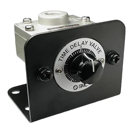
- Page 1 Doc. no.VM*-OMR0038-B PRODUCT NAME Time Delay Valve MODEL / Series / Product Number VR2110...
-
Page 2: Table Of Contents
Contents Page 1. Safety Instructions 2 ~ 9 2. Application 3. Specifications 4. How to Order 5. Operation Patterns 6. Characteristics 11 ~ 12 7. Dimensions... -
Page 3: Safety Instructions
Safety Instructions These safety instructions are intended to prevent hazardous situations and/or equipment damage. These instructions indicate the level of potential hazard with the labels of “Caution,” “Warning” or “Danger.” They are all important notes for safety and must be followed in addition to International Standards (ISO/IEC) , and other safety regulations. - Page 4 Safety Instructions Caution The product is provided for use in manufacturing industries. The product herein described is basically provided for peaceful use in manufacturing industries. If considering using the product in other industries, consult SMC beforehand and exchange specifications or a contract if necessary. If anything is unclear, contact your nearest sales branch.
- Page 5 Design precautions Warning ! (1) Actuator drive When an actuator, such as a cylinder, is driven, take appropriate measures (cover installation or approach prohibition) to prevent potential danger caused by actuator operation. (2) Maintenance space When installing the products, allow access for maintenance. (3) Ventilation Provide ventilation when using a valve in a confined area, such as in a closed control panel.
- Page 6 Mounting Caution ! (1) Tube, other than coil tube, should be used for static piping. For example, if a flexible moving tube is used, it may become worn, elongated, disconnected from the fitting, or torn due to tensile forces. Before using, ensure the tube is in a static condition at all times. After installation and maintenance, apply air supply to the equipment and perform appropriate functional and leakage inspections to verify the equipment is mounted properly.
- Page 7 Lubrication Caution ! (1) The product has been lubricated for life by the manufacturer and does not require additional lubrication while in service. (2) Use turbine oil Class 1, ISO VG32 (with no additives), if lubricated. Besides, if the lubrication is suspended halfway, the original lubricant will be lost and may result in a malfunction.
- Page 8 Operating Environment Warning ! (1) Do not use in an environment where corrosive gases, chemicals, sea water, water or steam are present. (2) Do not operate in a location subject to vibration or impact. (3) Use a protective cover, etc. to shield the product from direct sunlight. (4) Shield the product from radiated heat generated by nearby heat sources.
- Page 9 1-2. Time Delay Valve Specific Product Precautions Air Source Caution ! (1) Use regulated air using a regulator for input signal air. When the input signal air fluctuates, there will be larger differences in the delayed time, making it impossible to obtain the intended functions. Make sure to regulate the air using a regulator to avoid any influence of pressure fluctuation due to air consumption of other equipment.
- Page 10 Maintenance Warning ! (1) Perform inspection on a regular basis as necessary, such as at the beginning of operation, to verify that the Time Delay Valve operates properly. (2) Check whether the bolts on the mounting surface or the VR21 body are loose or damaged.
-
Page 11: Application
2. Application For design of a sequence control using pneumatic pressure, delayed operation is necessary as one of the basic functions. The VR2110 Time Delay Valve is used to delay the operation in a general industrial pneumatic circuit. 3. Specifications... -
Page 12: Operation Patterns
5. Operation Patterns ON timing: ON upon the set delay Output method: Normal close Settable time delay: 0.5 to 60 seconds Operation time chart is shown in Fig. 1. Time delay (Input signal) Time (Output) Fig. 1: Operation timing chart When an Input Signal Pressure is provided, Output turns ON after the preset time. - Page 13 (2) Input signal pressure and the set delay time Input signal pressure and supply pressure are fed from separate lines for the VR2110 Time Delay Valve. It is possible to operate the valve at pressure levels independent of each other.
-
Page 14: Dimensions
7. Dimensions ø4 EXH port Input signal port( PIL ) 2 x 1/8 Output port 2( A ) R port Supply pressure exhaust port Supply port on the other side 1( P ) 2 x M6 x 1 thread depth 8 (Panel mounting screw) Bracket mounted Panel mounted... - Page 15 Revision history A:Update VM to VM100-A B: Note added on page 8, weight corrected on page 10. Incorrect description corrected on page 12, outside diameter dimension drawing layout changed on page 13. 4-14-1, Sotokanda, Chiyoda-ku, Tokyo 101-0021 JAPAN Tel: + 81 3 5207 8249 Fax: +81 3 5298 5362 https://www.smcworld.com Note: Specifications are subject to change without prior notice and any obligation on the part of the manufacturer.
Need help?
Do you have a question about the VR2110 and is the answer not in the manual?
Questions and answers