Advertisement
Advertisement
Table of Contents

Related Manuals for Azkoyen VITRO X1


Summary of Contents for Azkoyen VITRO X1
- Page 1 Technical information VITRO X1...
- Page 2 Technical Principles Avda. San Silvestre, s/n 31350 Peralta (Navarra) Spain Tel.: +34 948 709 709 Cliente.azkoyenvending.es I N D E X INTRODUCTION 1.1. DEFINITIONS 1.2. MODELS 1.3. PRINCIPAL TECHNICAL CHARACTERISTICS DESCRIPTION OF COMPONENTS 2.1. PRINCIPAL COMPONENTS 2.2. HYDRAULIC CIRCUIT INSTALLATION AND SWITCHING ON 3.1.
-
Page 3: Technical Principles
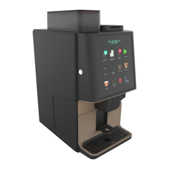
Technical Principles 1ª review – UK 12 – 2020... - Page 4 Technical Principles INTRODUCTION The semiautomatic machines of the Vitro X1 series are destined for the elaboration of espresso coffee and soluble drinks consisting of the mixing of warm water with product in powder or granulated. In the rest of the book, and for major briefness, the elements that are indicated will be named like: The machines of the series Vitro X1: machine or machines.
- Page 5 Technical Principles MODELS AND PRINCIPLE TECHNICAL CHARACTERISTICS The purpose of the Vitro X1 range is to make espresso coffee, which can be combinated with two soluble products. The machine can also produce soluble products independent of espresso coffee and has a direct outlet to the cup of hot water.
-
Page 6: Description Of Components
Technical Principles DESCRIPTION OF COMPONENTS 2.1. MAIN COMPONENTS 1ª review – UK 12 – 2020... - Page 7 Technical Principles Coffee beans hopper/canister It has a capacity of 1,2 kilograms. A manual lock allows the user to remove the canister without loosing any bean. Instant product hopper With a capacity of 1,6 litres in each one of the hoppers of instant for instant products. The approximate weight of the product is: Capacity in grams Product...
- Page 8 Technical Principles A motor spins the mixing Blade. Motor technical data: Motor manufacturer Mabuchi Voltage 34 Vcc Power 20 w Speed 15.000 rpm Mixing assy can be removed by pulling untill free the clipping pivots. Then unscrew the fixing screw and twist the motor to the right to set free the clips. In case of total dissambly;...
-
Page 9: Coffee Grinder
0.026 mm Turning the handle anticlockwise gives a coarser grind and moving it clockwise gives a finer grind. The grinder used in Vitro X1 is regulated by time. Grinder programming in function 315 (check details in programming manual) To get the desired amount of coffee for your Service: first adjust the “grinding point” using the handle. - Page 10 Technical Principles To remove from its position of anchor, the lower lever must be turned and the two upper screws must be loosened, as indicated in the photographs. If the group was in brewing position, to remove it, it is necessary to acces programming function 30 and raise the piston. To put the group back on the machine, it can be in any position and not matter that it has been turned out of the machine: Just put it in its place and fix its two anchor levers;...
- Page 11 Technical Principles The motor assembly positions the piston and exerts appropiate pressur on the coffee tablet, according to the grinding time or grams settings that is made in the recipe. D8. Micro switch positioning. D9. Motor connector. D10. Gear box motor The apper piston assembly has a pinion that is coupled to the engine, to make the right compression to the coffee tablet according to its number of grams.
- Page 12 Technical Principles A10. Volumetric counter Its function is to measure the quantity of water that is pumped for the elaboration of the espresso coffee A blade inside it spins boosted by the water flow. Two magnets on the blades activate a terminal locate on the counter cap. The three terminals on the cap are positive, negative (5V cc) and the _П_ (square signal symbol).
- Page 13 Technical Principles A12. Boiler The boiler works under pressure and has a capacity of 700 cc. It warms up the water for the elaboration of the products, espresso coffee or soluble products. F1. Temperature sensor F2. Clixon, rated at 120º C F3.
- Page 14 Technical Principles The water recedes back from the infusion element towards the third outlet because of the pressure it was submitted to by the pump in the infusion process. I1. 3rd outlet open I2. Infusion element joined to atmospheric pressure I3.
- Page 15 Technical Principles ºC 100,00 100,39 100,78 101,17 101,56 101,95 102,34 102,73 103,12 103,51 103,90 104,29 104,68 105,07 105,46 105,85 106,24 106,63 107,02 107,40 107,79 108,18 108,57 108,96 109,35 109,73 110,12 110,51 110,90 111,28 111,67 112,06 112,45 112,83 113,22 113,61 113,99 114,38 114,77 115,15 115,54 115,93 116,31 116,70 117,08 117,47 117,85 118,24 118,62 119,01 119,40 119,78 120,16 120,55 120,93 121,32 121,70 122,09 122,47 122,86 123,24 123,62 124,01 124,39 124,77 125,16 125,54 125,92 126,31 126,69...
- Page 16 H2. Control pcb H3. Display H4. Push buttons board Vitro X1 range machines have . The control 2 electronic boards, a Control board and a key board unit provides the supply voltages for the rest of the components and managing the machine.
- Page 17 Technical Principles a pre-selection is pressed, only the product labels affected by that pre- selection are illuminated, the rest is turned off. On the electronic pushbutton card, the display is connected, which is of the alphanumeric type with two lines of 16 characters each. The pushbutton card is tied with 4 plastic nuts and protected by a plastic panel.
-
Page 18: Installation And Switching On
Technical Principles INSTALLATION AND SWITCHING ON 3.1. Installation The power supply of the machine requires a socket, or another system, that allows its disconnection. The method used must guarantee the complete disconnection of both poles. Elemental safety requirements: Never touch any mechanisms with wet hands or feet. Never connect or use the machine barefoot. -
Page 19: Electrical Connection
Technical Principles Electrical connection The supply voltage of the machine is indicated in the characteristics plate, there is one inside the machine and another on the back. Depending on the machine code and the country, it can operate at 110 or 220 Vac, with a frequency of 50 or 60 Hz. -
Page 20: Error Messages
Technical Principles 4. ERROR MESSAGES In the following table there are described the errors that the machine can detect. The machine displays this warning for approx. 1 LOW TEMPERATURE min. on being started up. Check the water supply. ERROR: NO WATER Fill the water tank Load the hopper with coffee NO COFFEE BEANS... -
Page 21: Control Points
Technical Principles CONTROL POINTS Heatting element Meassured in the control board in the conector jp11 Between pins 1 and 3, will be 220 Vca when heatting element is working. (if 10A fuse is fine) Erogation pump Meassured in the control board in the conector jp10 Between pins 1 and 7 will be 220 Vca when ulka pump is working. - Page 22 Technical Principles Doser microswitch Meassured in the control board in the conector jp1. Between pins 4 and 11 will be 5 Vcc when doser is full. Between pins 4 and 11 will be 0 Vcc when doser is empty. Group motor microswitch Meassured in the control board in the conector jp1.
-
Page 23: Cleaning And Maintenance
Technical Principles CLEANING AND MAINTENANCE Daily Solid waste bucket. Empty the coffee residues and rinse with clean water. Liquid collector tray. Clean with a water and dish washing liquid solution. Beaters. Carry out various auto-cleaning operations by pressing button “B” on the ... - Page 24 Technical Principles 1. Remove the nut that holds the spindle shaft at the bottom of the group, it is recommended to support with a screwdriver the shower filter at the same time 2. Push the shaft from the bottom and remove the filter holder 3.
- Page 25 Technical Principles WORKING CONDITIONS AND NORMS The optimum working conditions of this equipment is achieved by fulfilling the following requirements: Temperatures: Storage: -25 to + 70ºC. Working: 0 to 50º C. Maximum relative humidity without condensation 85% ...
- Page 26 Technical Principles VOLUMÉTRIC DIMENSIONS Measurements in mm and weight in Kg. Model width height depth weight Vitro X1 Se+2 672 (X) 337 (Y) 505 (Z) 42 kg 1ª review – UK 12 – 2020...
Need help?
Do you have a question about the VITRO X1 and is the answer not in the manual?
Questions and answers
I have a Azkoyen Vitro x1 that is not heating. It shows a low temp and a resistor fault on screen. What do I need to look for.
For a heating issue and resistor fault on an Azkoyen Vitro X1, check the following:
- Measure voltage at the control board connector JP11 between pins 1 and 3. It should be 220 VAC when the heating element is working.
- Ensure the 10A fuse is intact.
- Check if the heating element is broken or disconnected.
This answer is automatically generated
Vitro x1 no power
The Azkoyen Vitro X1 may not be powering on due to several possible reasons:
1. Power Supply Issues – Ensure that the electrical installation, outlet, and automatic circuit breaker are correctly sized for the machine’s consumption.
2. Transformer Failure – The transformer (96 VA) provides power to components. If faulty, the machine may not receive power.
3. Control Board Issues – The control PCB manages power distribution. A malfunction or firmware issue could prevent startup.
4. Incorrect Installation – An inadequate electrical installation may cause power failure.
5. Safety Precautions – If the machine was moved incorrectly (tipped, dragged, or shaken), internal components might be damaged.
Checking the power source, transformer, control board, and installation setup can help diagnose the issue.
This answer is automatically generated