
Related Manuals for Azkoyen VITRO M5


Summary of Contents for Azkoyen VITRO M5
- Page 1 Avda. San Silvestre s/n 31350 Peralta (Navarra) Tfno. 948 709 709 https://cliente.azkoyenvending.es VITRO M5 – TECHNICAL MANUAL v0-10060-EN...
- Page 2 CONTENTS SAFETY AND WARNINGS ....................3 DESCRIPTION OF VITRO M5 ..................10 INSTALLATION ......................42 CLEANING AND MAINTENANCE ..................60...
-
Page 3: Safety And Warnings
SAFETY AND WARNINGS SYMBOLS The warning triangle appears in the instructions to warn users that failing to observe the safety warnings may result in a risk of personal injury or damage to materials. Danger, high risk that could cause serious or fatal injuries. - Page 4 • Do not tamper with the machine or change any of its elements, following the instructions included in the documents supplied by Azkoyen at all times for these procedures. • A damaged power supply cable can cause electric shock. Check it on a regular basis.
- Page 5 Hot water is poured out of the outlet tap during the initialisation process. Take care during initialisation. Risk of injuries by trapping with moving parts Several mechanisms exist in Vitro M5 which could cause injuries by trapping while being manipulated. •...
- Page 6 Change the water filter according to the maintenance plan established with the service provider. GENERAL CONSIDERATIONS • This machine must be installed by an Official Certified Technical Service. Only certified technicians have the skills and knowledge to install the machine, according to AZKOYEN’s specifications.
- Page 7 • AZKOYEN shall not be held liable for any damage caused by persons or materials due to: ▪ Faulty installation ▪ Improper electrical and/or hydraulic circuit installation ▪ Failure to clean the machine properly or incorrect maintenance ▪ Use of the machine for purposes other than the design purpose or under conditions out of the specifications ▪...
- Page 8 Latest food regulations AZKOYEN guarantees that all elements in contact with water or food products comply with the legal requirements established in regulation (EC) 1935/2004 or subsequent updates, in relation to materials and objects used that come in contact with food.
- Page 9 The machine features internal elements that are live with dangerous voltages. Do not disconnect the machine’s elements. These procedures are only authorised to the Technical Service. The power cable must only be replaced by the technical staff authorised by AZKOYEN. •...
-
Page 10: Description Of Vitro M5
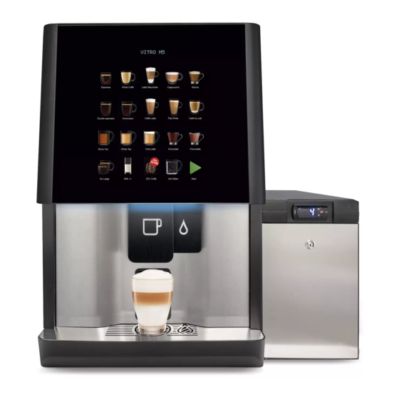
RANGE Vitro M5 is based on Vitro S5. To sum up, Vitro M5 is part of Vitro S5, which also features the capacity to serve milk in its natural condition. For this service, the Vitro M5 range features an innovative module that prepares and serves milk in liquid form and frothy milk. - Page 11 Versions, according to the machine’s main elements Code Description Beverages based on freeze-dried soluble product. Espresso coffee beverages. 20-key selection touch panel In ESP models, V10 is the standard 8 g espresso group. In ESP models, V20 is the standard 14 g barista group. Variable capacity espresso group, from 7 to 14 g.
- Page 12 MAIN COMPONENTS Front view – Touch panel, 20 selections – Alphanumeric display – Refrigerator FG16i DGT – Programmable thermostat – Independent hot water outlet – Folding cup holder – Liquid evacuation grille – Service head – Front service panel – Door liquid collection tray A9 –...
- Page 13 Inner front view B1 – Coffee bean container B2 – Soluble product hoppers B3 – Beaters B4 – Hot water outlet B5 - Refrigerator temperature control B6 – Milk container B7 – Milk suction tube B8 – Programming connector B9 – Tray level sensor B10 –...
- Page 14 A1. Selection touch panel The Vitro S5 model may feature one of the following types of keyboards: basic keyboard with 12 keys, with 8 direct product selection keys and 4 pre-selection keys, or the keyboard with 20 keys, with 19 product selection keys and 1 inactive key.
- Page 15 A2. Alphanumeric display The display is connected to the electronic push-button card, which has two lines of 16 alphanumeric characters each. A3. Natural milk refrigerator The natural milk storage refrigerator is a key component in the fresh milk system. This is an independent unit placed on one side of the machine or under the counter, which features a tank with a 9-litre capacity in the supply unit.
- Page 16 Main features Designation Volume Container Power supply Volumetric dimensions capacity voltage FG16I DGT 13 litres 9 litres 220-240 Vac/50 Hz B5. Refrigerator temperature control It is hosted on the upper part of the refrigerator’s front panel and it is used to configure the different parameters required to control the container’s temperature.
- Page 17 AZKOYEN. Extracting the container from the refrigerator B7. Milk suction tube...
- Page 18 A10. Door liquid collection tray It hosts a 1.2-litre tank that recycles the liquids spilled in the dispenser area. This tray is released by using two knobs on the rear of the door. The tray features two magnets, which maintain it steady in its position, so it can be easily removed from the front by simply releasing it from these two fastening elements.
- Page 19 Azkoyen tool no. 10040130 in its parts catalogue should be used to perform this.
- Page 20 (See A16, hot water boiler). B8. RS-232 Programming connector RS232 service connector for connection with a programming cable to a PC. The Azkoyen Configurator application can be used to perform the following service operations: ▪...
- Page 21 B9. Liquid waste tray level sensor When the waste in the tray reaches the maximum level, this sensor detects it by the continuity of the two “ ” electrodes in contact with the liquid. The machine will show the Liquid tray full error on the display.
- Page 22 The elements of the brewing group and piston are manufactured in resin and are the elements used to brew the ground coffee dose. Azkoyen offers three coffee groups with different features and capacities. The Vitro S5 models may incorporate any of the three types of groups: 1.
- Page 23 To remove the AZK 30 group, in addition to the lower lever and the upper nut, release the bolt shown in the image above. AZK 10 - AZK 20. Washer position and coffee capacity The piston features a spring and two washers, which adjust the pressure of the piston on the ground coffee, depending on their position.
- Page 24 AZK 30. Variable group The AZK 30 group has a variable and automatic positioning system, handling from 7 to 14 g, thanks to a 24 VDC position control motor. The variable group allows a more controlled dosing system and better pressing results, since the piston is positioned by the activation of a DC motor, controlled by a pulse meter.
- Page 25 0.026 mm points Vitro S5 machines feature Azkoyen’s M03 grinder. The grinder features flat grinding bits, dosing the amount of ground coffee in different time slots, without the need to use a volumetric dosing system. In addition, they offer a smoother and lighter coffee grinding process.
- Page 26 B18. Production extraction chutes It is used to remove the soluble product from the corresponding hopper and transferring it to the product beaters. It features a Mabuchi motor and a gear motor developed by Azkoyen. Motor brand Mabuchi Power supply voltage...
- Page 27 B21. Pressure pump This element is responsible for taking water from the cold water tank and transferring it to the boiler. The cold water drives the water inside the boiler towards the soluble product EVs or to the espresso coffee brewing group. E1.
- Page 28 Technical features: Power supply voltage 120/230 Vac Nominal power 48 W Operating pressure 8 kg/cm² Maximum pressure 12 kg/cm² B22. Cold water tank It is manufactured in copolyester (PCTA) and has a 500cc capacity for water. It operates at the atmospheric pressure and temperature.
- Page 29 F1. Temperature sensor (PTC) F2. 120ºC Safety thermostat F3. 1,800 W heater resistor F4. Electrovalves F5. Upper cover F6. Lower cover F7. Water inlet The espresso and soluble product electrovalves are found on a support bolted onto the boiler. The espresso EV is a 3-way valve: a boiler outlet way, a way used to access the group, and a third way, which when at standby, allows the group to be set at the environmental pressure.
- Page 30 When the machine stops brewing espresso, the 3-way EV is set to standby, so it closes the water outlet from the boiler and the group is connected to the third way. Therefore, the water that could not flow through the coffee during the brewing process and which is held inside the group, will be driven through the third way to the waste container.
- Page 31 ºC 100.00 100.39 100.78 101.17 101.56 101.95 102.34 102.73 103.12 103.51 10 103.90 104.29 104.68 105.07 105.46 105.85 106.24 106.63 107.02 07.40 20 107.79 108.18 108.57 108.96 109.35 109.73 110.12 110.51 110.90 11.28 30 111.67 112.06 112.45 112.83 113.22 113.61 113.99 114.38 114.77 15.15...
- Page 32 200 175.84 176.21 176.57 176.94 177.31 177.68 178.04 178.41 178.78 79.14 210 179.51 179.88 180.24 180.61 180.97 181.34 181.71 182.07 182.44 82.80 220 183.17 183.53 183.90 184.26 184.63 184.99 185.36 185.72 186.09 86.45 230 186.82 187.18 187.54 187.91 188.27 188.63 189.00 189.36 189.72 90.09...
- Page 33 FRESH MILK MODULE The module is hosted to the left of the espresso boiler and is accessed from the rear panel. Rear view C1 – Fresh milk module...
- Page 34 Main components of the milk circuit 2.3.1 Overview – Air inlet for air injection – Cream adjustment control – Air inlet control EV – Milk heater element – Anti-return valve of the cleaning circuit – Milk inlet control EV – Milk suction channel to the refrigerator –...
- Page 35 C14. Milk pump Main features: • Power supply: 24 VDC • It is used to supply milk during service. • The amount of air required is injected in the milk flow for the milk-cream services. The pump supply procedure and the subsequent reduction of the conduit’s cross-section using a 0.6 mm ...
- Page 36 Functions: C3 – Air inlet • Air inlet. Need to froth milk Opens or closes the milk inlet. C6 – Milk inlet • Milk inlet. Controls the supply of milk from the refrigerator. C10 – Hot water inlet • Controls the hot water for cleaning processes, supplied by the 700cc boiler. C12 –...
- Page 37 – Control PCB of the Fresh Milk module – Hydraulic components and external refrigerator – Milk outlet EV – Power supply and I2C / CAN communications • Control PCB of the Fresh Milk module • It features different devices with I2C communications that allow different system elements to be controlled and the temperature to be monitored.
- Page 38 Technical datasheets 2.3.2 Dimensions Dimensions (mm) and weight (kg) VM5 - Width VM5 - Height / Height with base 775/1630 VM5 - Depth VM5 - No load weight F16i DGT - Width (Outer/Inner). 230/173 F16i DGT - Height (Outer/Inner). 390/277 F16i DGT - Depth (Outer/Inner).
- Page 39 Electromechanical components Electromechanical components Grinder M03 / flat grinder bits 230 VAC 50 Hz / 400 W / 1,250 rpm / ULKA EX5 Brewing pump 230 VAC 50 Hz / 48 W Espresso group gear motor 230 VAC 50 Hz / 85 W / 7.3 rpm Espresso boiler resistor 230 VAC 50 Hz / 1,400 W / ...
- Page 40 Environmental conditions Environmental conditions and environment in which the machine is used Temperature range +1ºC to +40ºC Maximum relative humidity 65% rH IP Degree of protection For indoor use only Maximum tilt, any axis 2º Sound level 80 db(A) Load capacity/selections Capacity/Volume Coffee bean container capacity 2.6 kg...
- Page 41 No. selection keys 12 or 20 capacitive keys Selection - 12 keys 8 selections + 4 pre-selections Selection - 20 keys 19 selections + 1 inactive Connections and user interface Connections / Access interface / Telemetry Connections / Interface USB via RS232 interface Application SW / service AZK beverage configurator OS Compatibility...
-
Page 42: Installation
INSTALLATION PRELIMINARY INSTALLATION CONDITIONS • The installation and start-up procedures require previous planning. • The owner/operator will responsible for completing all work required to connect the electrical, hydraulic and waste connections. These tasks must be carried out by authorised technicians, in compliance with the local regulations, and must be completed before the machine is installed. - Page 43 Environmental conditions 3.1.2 • The equipment must be installed indoors and not subject to outdoor conditions (frost, rain, etc.). • Ambient temperature, between +10ºC and 40ºC • Maximum relative humidity of 65% Rh. Volumetric dimensions 3.1.3 Maximum dimensions 3.1.4 1275...
- Page 44 The refrigerator can be installed on the right side, left side or under the counter. • Refrigerator options: o Azkoyen supplies the FG16i DGT refrigerator as an accessory. This model is designed for the installation of a refrigerator as an accessory and it features different functions, such as sanitary temperature control and minimum level detector to control the level of milk in the container.
- Page 45 Vitro M5 settings. • Function 333 Step 1 - REFRIGERATOR YES/NO Used to define whether the refrigerator recommended by Azkoyen is used or not. • If you select YES: The machine will start to control the corresponding parameters and states via a series I2C connection: the sanitary temperature monitor and milk level control will be activated.
- Page 46 Do not exceed the maximum length of the suction tube. Failing to observe this could cause permanent damage to the milk pump and not guarantee the effectiveness of the cleaning cycles. The warranty does not cover damage caused by this. Electrical connections 3.1.6 •...
- Page 47 • Azkoyen does not recommend the use of socket extenders. If these need to be used, the ’ cables must have a minimum cross-section of 1.5 mm and the manufacturer recommendations must be observed • Guide the power supply cable so it is not in contact with sharp surfaces or ensure it cannot become snagged by nearby objects.
- Page 48 Network connection characteristics • ” Machine connections: 3/4 male. • The water connection must feature a shut-off valve, allowing it to be closed. • – Admissible network pressure: 0.098 MPa 0.98 MPa • Minimum flow rate: 5 l/min. • The water connection hose is not supplied with the machine. •...
- Page 49 Evacuating waste through the counter/tabletop • The base of the Vitro M5 cabinet features holes to evacuate waste from the bottom. The solid waste evacuation area features holes, but additional ones can be opened with pliers. Liquids are evacuated through the 28 mm hole found under the tray ’...
- Page 50 INSTALLATION AND START-UP Pre-condition checks 3.3.1 Check that the installation requirements described in point 3.1 are met. Removing the packaging from the equipment 3.3.2 Remove the packaging from the machine and its accessories. Remove the protective materials and save the accessories and documents for subsequent steps.
- Page 51 3.3.4 Machine-refrigerator fastening flange The fastening flange ensures that both units are fastened together, preventing the milk suction tube from being damaged or trapped, thus preventing the product from being supplied. The joint is fastened using the refrigerator legs. Release those on the corresponding side and fasten the flange as indicated in the image.
- Page 52 The default factory configuration is with this tube mounted on the right side of the machine, when viewed from the front. Make sure that the tube is not bent or snagged. Make sure that the filter mounted on the end is inside the milk container. Machine-refrigerator I2C bus connection 3.3.7 ...
- Page 53 3.3.9 Adjusting the cold temperature setpoint 1 & 3 Hold down for 3 seconds to access the programs Press the keys indicated here to increase or decrease the desired Temperature setpoint value. Press once to adjust the temperature value Considerations 1) If the display is off, hold down the ON/OFF button for a few seconds to activate the...
- Page 54 7) Press the ON/OFF button to increase the temperature by 1 unit intervals and the light bulb button to decrease it. 8) Press Set to exit after the desired temperature has been configured. Connecting the machine to the mains and configuring the panel 3.3.10 ...
- Page 55 Calibrating the frothing level F030 3.3.12 Calibrating the frothing function. The dispenser arm features the control to adjust the cream consistency. It is adjusted at the factory for a level that is suitable in most cases. If the customer would like to change the consistency, open or close the valve for no more than ½...
- Page 56 Freeze-dried products have a limited useful life after storage. Only fill the machine with the amount of product you wish to consume, ideally, for that same day. You can attach the maximum level labels included in the accessory bag to mark these levels. Therefore, you can indicate the most suitable filling level, according to the expected consumption level.
- Page 57 Cleaning solution for fresh milk module 3.3.15 Filling with fresh milk The installation tests should be carried out with refrigerated milk (5ºC). Milk at ambient temperature may not produce the desired frothing results and the effect of temperature might be confused with deficient operation. ...
- Page 58 We recommend using ultra-heated UHT milk to guarantee the safety levels with regards to the proliferation of germs. The container must be opened for a maximum of 24h before this process to guarantee that a high-quality cream is served. Milk at ambient temperature may not produce the desired frothing results and the effect of temperature might be confused with deficient operation.
- Page 59 HYDRAULIC FRESH MILK CIRCUIT General operation • The main functions of the module are: o Supply of liquid or frothy milk, at the ambient temperature or hot. o Cleaning the water circuit after each service, automatically. o In-depth cleaning of the circuit with detergent on a daily basis; this procedure is activated by the user.
-
Page 60: Cleaning And Maintenance
CLEANING AND MAINTENANCE Regular cleaning of the Vitro M5 and its accessories is vital to guarantee food safety and the highest quality of the beverages served. The regular cleaning tasks are described in this chapter. Under no circumstances can these actions be omitted. - Page 61 • We also recommend using the cleaning solution supplied by AZKOYEN to clean all milk remains thoroughly. A small dose of 20 ml can be diluted in 5 l of lukewarm water.
- Page 62 Recommended cleaning products Fresh milk module cleaning Espresso group cleaning Disinfectant spray for HoReCa solution. tablets. surfaces. Ref. 41250180 Ref: 09725700 Ref: 09725710 CLEANING TASK FREQUENCY • The table below shows the elements that require regular cleaning and the cleaning frequency. These intervals must be strictly observed.
- Page 63 System Element ⚫ Fresh milk module ⚫ Milk container Milk ⚫ Milk suction tube ⚫ Milk tap ⚫ Refrigerator ⚫ Coffee bean container Espresso ⚫ Brewing group ⚫ Espresso tap ⚫ Instant product containers Soluble ⚫ Instant product beaters ingredients ⚫...
- Page 64 FRESH MILK MODULE CLEANING INSTRUCTIONS Remove the milk tank. Drain. Wash with water and neutral soap and let dry. Place the blue cleaning tank inside the refrigerator and place the suction tube inside it. Press D on the programming control. ...
- Page 65 Container removed to add Pour the dose into the Fit the dosing device onto the cleaning solution. the cleaning element. blue container. Place the container in the Open the cover in the vertical position and press refrigerator and press “D”...
- Page 66 Remove the cleaning tank. Use a cloth dampened in water and the cleaning solution to clean the following: 1) the inner surfaces of the refrigerator and 2) the outside of the suction tube; dry all surfaces with a clean and dry cloth.
Need help?
Do you have a question about the VITRO M5 and is the answer not in the manual?
Questions and answers