Table of Contents
Advertisement
Advertisement
Table of Contents

Related Manuals for Azkoyen AZKOY GROUP VITRO S5


Summary of Contents for Azkoyen AZKOY GROUP VITRO S5
- Page 1 USER MANUAL «VITRO S5» ESPRESSO REFERENCE MANUAL: 81044280; EDICIÓN 09-2017...
- Page 2 User Manual - 2 -...
-
Page 3: Table Of Contents
User Manual INDEX CAUTIONS ..........................4 CHAPTER 1. GENERAL CHARACTERISTICS ................ 7 1.1.- Description of the VITRO S5 line................... 7 1.2.- Main characteristics ....................... 7 1.3.- Description of the main components ................8 CHAPTER 2. INSTALLATION AND START-UP ..............11 2.1.- Choosing a machine location .................. -
Page 4: Cautions
All rights are hereby reserved. No part of this document may bephotocopied, reproduced or translated without the prior written consent of AZKOYEN. AZKOYEN hereby declines all liability for damages caused to persons or things as a result of the following: o Incorrect installation. - Page 5 FOR ANY ADDITIONAL INFORMATION THAT IS NOT SPECIFIED HEREIN CONTACT YOUR DISTRIBUTOR OR ACCESS THE TECHNICAL MANUAL FROM AZKOYEN'S OFFICIAL WEBPAGE This symbol on a label indicates if you need more information, you can be found in the User Manual.
- Page 6 User Manual - 6 -...
-
Page 7: Chapter 1. General Characteristics
CHAPTER 1. GENERAL CHARACTERISTICS 1.1.- Description of the VITRO S5 line. The machines of the AZKOYEN VITRO range are TABLETOP type dispensers of coffee and soluble drinks, and they are especially designed for use in places with average coffee consumption, such as waiting rooms, medium sized offices, etc. -
Page 8: Description Of The Main Components
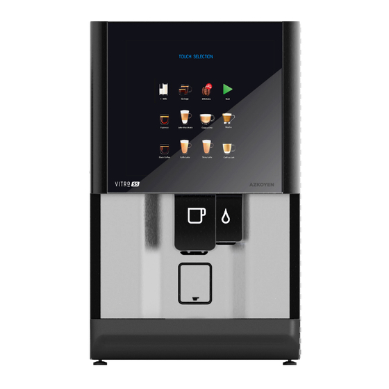
User Manual 1.3.- Description of the main components Figura 1. Figure 1. Fig. 1 Coffee bean Hopper Cabinet Mixers Espresso coffee unit Coffee bean tray Liquid spill tray Soluble product hoppers Fig. 2 Information screen Sellection buttons lift cup Figure 2. - 8 -... - Page 9 User Manual Figure 3. Fig. 3 1 Hopper 2 Hopper flow gate 3 Mill regulating handle 4 Uper piston 5 Lower unit 6 Unit securing lever - 9 -...
- Page 10 User Manual - 10 -...
-
Page 11: Chapter 2. Installation And Start-Up
The machine must be positioned on a piece of furniture or support such that it is stable and cannot be accidentally tipped over. AZKOYEN can supply a stand especially designed for this range of machines. If you would like more information, consult your distributor 1. - Page 12 User Manual 4. Drill a drain hole in the plastic tray using an Ø 8 drill bit (you will see the "blind" hole to be drilled at the bottom of the tray.). 5. Remove the sensor cable from the spill tray, fastened to the coin box bracket, and lead it to the waste bin of the stand as shown in the figure.
- Page 13 User Manual Waste container assembly according to the type of machine Sensor Fresh Brew Coffee grounds Ties tray Stand-alone cantainer area Tubes for solid wastes Espresso & Solid wastes Instant container Liquid waste container - 13 -...
-
Page 14: Changing The Product And Price Sign
User Manual 2.6.- Changing the product and price sign Disconnect the machine and remove the plastic nut that fastens the top of the buttons. Pull back the cover to remove the selections menu. Press on the side of the label holder to release the row of labels you want to change. -
Page 15: Load Level Labels Of The Hoppers
User Manual 2.8.- Load level labels of the hoppers Some of the soluble products may require shorter reloading cycles in order to prevent its expiry, or the loss of properties. The machine incorporates "top-level labels" as an additional provision. These will inform the person responsible for the loading the product what is the maximum level of each hopper. - Page 16 User Manual - 16 -...
-
Page 17: Chapter 3. Filling The Machine
3.4.- Initial programming The machine will be sent with the programming predefined by AZKOYEN. In order to modify any of the values of the functions, enter the basic menu (see chapter 4) and program the new functions. - Page 18 User Manual - 18 -...
-
Page 19: Chapter 4. Configuration And Programming
User Manual CHAPTER 4. CONFIGURATION AND PROGRAMMING 4.1.- What is programming? The machine is cable of performing a series of functions that you can configure. The programming is the actions that you establish in order to determine how the machine will operate in certain functions. The machine is cable of performing a series of functions that you can configure. -
Page 20: Direct Access To A Function
User Manual Operation of the programming control unit in the programming mode. There are four “editing modes” for communicating with the machine in order to program values in the functions. PRESSING THE KEY Key A The digit being edited goes up one character in the table. Key B The digit being edited goes down one character in the table. - Page 21 User Manual The symbol of the editing mode that is used with the function is displayed next to each function. The symbols are the following: EXE Direct execution function. Option list editing mode. AB1 Alphanumeric editing mode. PROP Editing mode proper to the function Numerical editing mode.
-
Page 22: Service Programming
User Manual 4.5.- Service programming. 4.5.1.- What is a service? A service is the act that the machine performs every time that a customer presses a selection. When programming a service, each step that the machine needs to take to complete the selected operation must be programmed. - Page 23 User Manual If the option, MODIFY A STEP, is selected, the machine will display the CONFIGURATION SCREEN of the step: Change the values using the programming control keys. The functions of the keys are as follows: A or B - Go up or down the "steps" C or D - Increase or decrease the amounts (move the bar forward or backward in the figure) The water volumes are measured in seconds.
- Page 24 User Manual - 24 -...
-
Page 25: Chapter 5. Anomaly Control And Maintenance
User Manual CHAPTER 5. ANOMALY CONTROL AND MAINTENANCE 5.1.- Reset If the machine is out of service, enter and exit programming by pressing key C on theprogramming box twice. 5.2.- Possible incidents during a service. If the machine is without of coffee beans or if there is a problem with serving espresso coffee, the machine allows services of soluble product. -
Page 26: Disassembly Of The Coffee Bean Unit
User Manual 5.4.- Disassembly of the coffee bean unit Use the 030 function to place the group in standby. In order to disassemble the complete lower unit, turn the anchor levers of the unit and remove the unit by pulling it outwards. In order to remove the brewing piston, 1. - Page 27 User Manual Verify that the dosage is correct whenever an adjustment is made and perform a few coffee services to ensure proper operation. Adjusting the water temperature in the boiler. The machines are equipped with a single boiler, therefore the programmed temperature will be implemented in both the espresso services as well as in the services of other soluble products.
- Page 28 User Manual - 28 -...
-
Page 29: Chapter 6. Cleaning The Machine
User Manual CHAPTER 6. CLEANING THE MACHINE. 6.1.- Components that require regular cleaning 1. Sensor level of liquid wastes 2. Coffee grounds dregs tray (espresso machines only) 3. Liquid spill tray 4. To clean lift cup (by pressing B in the programming box and closing the door instantly of the machine with lift cup down) -
Page 30: Cleaning Cycle For The Group Brewing Chamber
User Manual Once a week Clean the mixer (Press B in the programming unit). or every 700 To clean lift cup (by pressing B in the programming box and closing the services door instantly of the machine with lift cup down). ... -
Page 31: Exterior Cleaning
User Manual Once the machine starts the cleaning cycle, it cannot be stopped. If you want to stop the cycle for any reason, you must switch the machine off and turn it back on again. When the cleaning cycle has finished, the machine will resume normal service. 030 TEST MACHINE GROUP CLEANING To run the cleaning cycle:... - Page 32 User Manual - 32 -...
- Page 33 User Manual - 33 -...
Need help?
Do you have a question about the AZKOY GROUP VITRO S5 and is the answer not in the manual?
Questions and answers
Are the units NSF approved
The Azkoyen AZKOY GROUP VITRO S5 unit uses a recommended sanitizer (STERA SHEEN) that is approved by NSF, but the document does not state that the unit itself is NSF approved.
This answer is automatically generated
Coffee Beans not filtering through
The coffee beans may not be filtering through in the Azkoyen Vitro S5 because the hopper flow gate is closed. Ensure that the flow gate is open to allow beans to pass through. Additionally, check if the hopper is properly installed and not blocked.
This answer is automatically generated
Group water flow fault