WEG CFW900 User Manual
Hide thumbs
Also See for CFW900:
- Installation manual (2 pages) ,
- Quick installation manual (121 pages)

Subscribe to Our Youtube Channel
Related Manuals for WEG CFW900


Summary of Contents for WEG CFW900
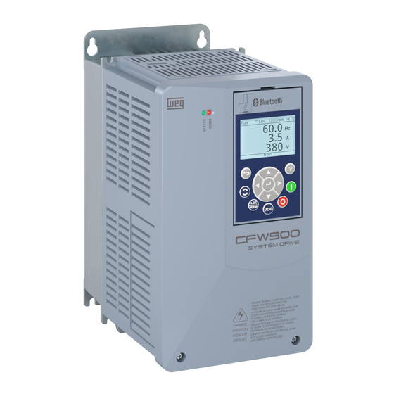
- Page 1 Motors | Automation | Energy | Transmission & Distribution | Coatings Frequency Inverter CFW900 User’s Manual...
- Page 3 User’s Manual Series: CFW900 Language: English Document: 10008985516 / 01 Models: Frame Sizes A, B, C, D and E Publication Date:04/2022...
- Page 4 SUMMARY OF REVISIONS The information below describes the revisions made to this manual. Version Revision Description First edition. Update of tables, figures and identification labels and general corrections.
-
Page 5: Table Of Contents
2.3 ABOUT THE CFW900 ........ - Page 6 CONTENTS 4.2 MENU ACCESS MODE - MENU LEVELS ............. 49 4.2.1 Reading Variables - Status and Diagnostics Menus .
- Page 7 CONTENTS 8.3.1 General Control Specifications ............... 8.3.2 Input and Output Specifications .
-
Page 8: Safety Instructions
SAFETY INSTRUCTIONS 1 SAFETY INSTRUCTIONS This manual provides information for the proper installation and operation of the CFW900 frequency inverter. Only trained and qualified personnel should attempt to install, start-up and troubleshoot this type of equipment. 1.1 SAFETY WARNINGS IN THIS MANUAL... - Page 9 NOTE! ✓ For the purpose of this manual, qualified personnel are those trained and able to: Install, power up and operate the CFW900 in accordance with this manual and the safety legal procedures in force; Provide first aid; Use the protective equipment according to the regulations in force.
-
Page 10: General Information
It is not the intention of this manual to present all the possibilities for the application of the CFW900, as well as WEG cannot take any liability for the use of the CFW900 which is not based on this manual. - Page 11 Rectifier: inverter input circuit that transforms the input AC voltage into DC, formed by thyristors and/or power 4 | CFW900...
-
Page 12: About The Cfw900
Self-Tuning function (Assistant) for the vector control allows the automatic setting of the regulators and control parameters,from the identification (also automatic) of the motor and load parameters. By navigating the CFW900 HMI, it is possible to set the parameters through the navigation groups: Status, Diagnostics and Configurations. - Page 13 External 24 V 24V, 0,8A Power Supply Protection Protection 10V, 10mA (backup) AO1-X AI1-X AO2-X Lettering Connectors Not included AI2-X Alternative wiring Isolation CFW900-IOS (*) All models have a built-in RFI filter. Figure 2.1: Block diagram for the CFW900 6 | CFW900...
- Page 14 A - surface mount brackets B - heatsink/back of inverter C - fan with mounting bracket D - XC1 connector (CFW900-IOS) E - CFW900-4SLOTS backplane F - CFW900-REL accessory board module G - front cover H - HMI Figure 2.2: Main components USB Connector...
-
Page 15: Identification Labels
2.3.1 Identification Labels There are two identification labels on the CFW900: a complete one, located on the side of the inverter and a condensed one, under the HMI. The label under the HMI brings the most important data even on inverters mounted side by side. -
Page 16: Receiving And Storage
2.3.2 Receiving and Storage The CFW900 is supplied in a cardboard box up to frame C models; the others are supplied in a wooden box. The package bears an identification label that must be identical to the one affixed to the side of the inverter. - Page 17 GENERAL INFORMATION If the CFW900 is not installed soon, store it in a clean and dry location (temperature between -25 °C and 60 °C (-13 °F and 140 °F), with a cover to prevent dust accumulation inside it. WARNING! When the inverter is stored for a long period, it becomes necessary to perform the capacitor reforming.
-
Page 18: Installation And Connection
INSTALLATION AND CONNECTION 3 INSTALLATION AND CONNECTION This chapter provides information on installing and wiring the CFW900. The instructions and guidelines listed in this manual shall be followed to guarantee personnel and equipment safety, as well as the proper operation of the inverter. - Page 19 650 [25.6] 275 [10.83] 318.5 [12.54] 318.5 [12.54] 316 [12.44] 620 [24.41] Frame E *Tolerance of the dimensions d3 and e3: + 1.0 mm (+ 0.039 in) *Tolerance of the other dimensions: ± 1.0 mm (± 0.039 in) 12 | CFW900...
-
Page 20: Horizontal Mounting
IP21 / UL type 1 150 [5.9] 250 [9.84] 20 [0.79] 30 [1.18] 3.1.3 Horizontal Mounting Frames A ... C can be mounted horizontally without derating the output current. The correct mounting position is shown in Figure 3.3. CFW900 | 13... -
Page 21: Cabinet Mounting
The portion of the inverter that is located outside the cabinet is rated IP55 / UL type 12. To ensure that the cabinet degree of protection is maintained, adequate sealing must be provided between the panel opening and the drive flange. Example: silicone gasket. 14 | CFW900... -
Page 22: Access To Control And Power Terminals
Figure 3.4: Repositioning of the mounting brackets 3.1.5 Access to Control and Power Terminals In CFW900 inverters of frames A, B, C and D, it is necessary to remove the HMI and the front cover to access the control and power terminals, as shown in Figure 3.5. - Page 23 In case of inverters of frame size E, it is necessary to remove the HMI and control rack cover to access the control connectors (see Figure 3.6). In order to access the power connectors, remove the lower front cover as shown in Figure 3.7. Figure 3.6: HMI and control rack cover removal 16 | CFW900...
-
Page 24: Hmi Installation At The Cabinet Door Or Command Panel (Remote Hmi)
Figure 3.8: Data for the HMI installation at the cabinet door or command panel - mm [in] 3.2 ELECTRICAL INSTALLATION DANGER! The following information is merely a guide for proper installation. Comply with applicable regulations for electrical installations. Make sure the AC power supply is disconnected before starting the installation. CFW900 | 17... -
Page 25: Identification Of The Power And Grounding Terminals
DC+/+UD: positive pole of the DC power supply. U, V and W: motor cable connection. The maximum tightening torque of the power terminals and grounding points must be checked in Table 3.4. DANGER! Observe correct DC power connection, polarity and position of the terminals. 18 | CFW900... - Page 26 flaps of the cover protecting the DC+, DC- and BR terminals and insert this new cover to seal the BR terminal, as shown in Figure 3.10. In this case, the cover of terminals R/L1, S/L2 and T/L3 must be kept. CFW900 | 19...
-
Page 27: Power And Grounding Wiring
The inverter will be damaged in case the input power supply is connected to the output terminals (U/T1, V/T2, or W/T3) Check all the connections before powering up the inverter. In case of replacing an existing inverter by a CFW900, check if the installation and wiring is according to the instructions listed in this manual. NOTE! ✓... - Page 28 Grounding (phillips) R/L1 ; S/L2 ; T/L3 ; U/T1 ; V/T2 ; W/T3 ; DC+ ; DC-. The first value is for 3-phase power supply and motor connection, and the second value is for single-phase power supply. CFW900 | 21...
- Page 29 Wire ferrule (phillips/ slotted) CFW900C70P0T2 3.7 (32.8) Grounding 16.0 (phillips) Power 35.0 Wire ferrule (phillips/ slotted) 3.7 (32.8) CFW900C80P0T2 Grounding 16.0 (phillips) R/L1 ; S/L2 ; T/L3 ; U/T1 ; V/T2 ; W/T3 ; DC+ ; DC-. 22 | CFW900...
- Page 30 1.2 (10.6) Fork Grounding (phillips) Power (phillips/ slotted) CFW900A04P8T4 1.2 (10.6) Fork Grounding (phillips) Power Fork (phillips/ slotted) CFW900A06P5T4 1.2 (10.6) Grounding (phillips) R/L1 ; S/L2 ; T/L3 ; U/T1 ; V/T2 ; W/T3 ; DC+ ; DC-. CFW900 | 23...
- Page 31 (phillips) Power Wire ferrule (pozidriv) CFW900C50P0T4 3.7 (32.8) 16.0 Grounding (phillips) Power 25.0 Wire ferrule (pozidriv) CFW900C62P0T4 3.7 (32.8) Grounding 16.0 (phillips) R/L1 ; S/L2 ; T/L3 ; U/T1 ; V/T2 ; W/T3 ; DC+ ; DC-. 24 | CFW900...
-
Page 32: Fuses, Circuit Breakers And Power Supply Capacity
3.2.3 Fuses, Circuit Breakers and Power Supply Capacity The CFW900 is suitable for use in circuits with short circuit capacity of up to 65 kA, which value varies according to the type of protection used (fuse or circuit breaker) and certification considered (UL or CE). For more details, Table 3.5,... - Page 33 Frame C: 500x800x600 mm Frame D: 500x1000x500 mm Frame E: 600x1000x600 mm For the use of frames C and D drives in grids with a short-circuit current capacity of up to 10 kA there is no minimum panel size. 26 | CFW900...
- Page 34 Mersen A70QS400-4 CFW900E0203T4 Mersen A70QS400-4 type J ≤450 A CFW900E0242T4 Mersen A70QS400-4 Panel with a minimum size of 1.5 times the size of the inverter. Minimum panel dimensions (width x height x depth): 600x1000x600 mm (23.6x39.3x23.6 in). CFW900 | 27...
- Page 35 INSTALLATION AND CONNECTION Table 3.7: Circuit breaker specifications as per UL and IEC standards Circuit Breaker Protection Weg Circuit Breaker recommendation Maximum Minimum Maximum Model Circuit Breaker Panel Short-Circuit Current Rated (CB type) (ACW type) Dimensions of the Power Supply [kA]...
-
Page 36: Pre-Charge Circuit Control Fuses
In case replacement is required, use control fuses as specified below or equivalent: 0.5 A / 600 V time-delay fuse. Manufacturer: Cooper Bussmann. Commercial reference: FNQ-R-1/2. WEG Item (material number): 10411493. Figure 3.11: Fuses for the control circuit 3.2.4 Power Connections PE R... -
Page 37: And Delta Corner Earthed Networks
It is also possible to operate the CFW900 in delta corner earthed networks, except for models of frame A. In these cases, the grounding screws of the filter capacitors must also be removed, as shown in Figure 3.13. -
Page 38: Dynamic Braking
This type of braking is used in cases where short deceleration times are desired or when high inertia loads are driven. The “Optimal Braking” feature may be used with the vector control mode, which eliminates in most cases the need of an external braking resistor. CFW900 | 31... -
Page 39: Sizing The Braking Resistor
For critical applications with very short deceleration times and high inertia loads (ex.: centrifuges) or short duration cycles, consult WEG for the adequate sizing of the braking resistor. -
Page 40: Installation Of The Braking Resistor
Use twisted cable for the connection. Separate these cables from the signal and control cables. Size the cables according to the application, respecting the maximum and effective currents. If the braking resistor is installed inside the inverter cabinet, consider its additional dissipated energy when sizing CFW900 | 33... -
Page 41: Output Connections
3.2.4.3 Output Connections WARNING! The inverter has an electronic motor overload protection that shall be adjusted according to the driven motor. When several motors are connected to the same inverter, install individual overload relays for each motor. 34 | CFW900... -
Page 42: Motor Cables
INSTALLATION AND CONNECTION WARNING! The motor overload protection available in the CFW900 is in accordance with the IEC609047-4-2 and UL61800-5-1, standards, note the following information: “Trip” current equal to 1.25 times the motor rated current (C2.1.5) adjusted in the Oriented “Start-up ”menu. -
Page 43: Connection Of The Motor Cable Shield To Ground
Figure 3.15: Motor connection cables recommended by IEC 60034-25 3.2.4.3.2 Connection of the Motor Cable Shield to Ground Inverters of the CFW900 series include clamps and grounding plates that simplify the connection of the control cables and motor cable shield, enabling a low impedance connection for high frequencies. -
Page 44: Grounding Connections
When installing several inverters, follow the procedures presented in Figure 3.18 for the grounding connection. WARNING! The neutral conductor of the network that powers the inverter cannot be used to ground the inverter. Figure 3.17: Grounding terminals CFW900 | 37... -
Page 45: Control Connections
INSTALLATION AND CONNECTION Panel 1 Panel 2 Internal panel grounding bar Figure 3.18: Grounding connections with multiple inverters 3.2.6 Control Connections Figure 3.19: CFW900 control connections 38 | CFW900... - Page 46 DIP switches S1 and S2: safety module configuration XC6 connector: DB9 connector for connecting the HMI/remote HMI Backplane CFW900-4SLOTS: provides four slots to connect accessories. By default, slot A is taken by the CFW900-REL-01. It can be replaced by the CFW900-7SLOTS, which has seven slots for accessories...
- Page 47 24 V power supply of the inverter control is not energized. If this characteristic is unwanted, the CFW900-REL-01 or CFW900-IOD-01 outputs must be used. Table 3.12: Configuration of DIP switches for selecting the type of signal on the CFW900-IOS analog inputs/outputs Input/Output DIP switch...
- Page 48 For more information see the detailed specification in Table 8.13. The CFW900-REL-01 supplied with the inverter will be connected to slot A, and the corresponding outputs will be 1A, 2A and 3A, with the default functions indicated. If the accessory is reconnected to another slot, the identification of the outputs will change to 1n, 2n and 3n, with...
-
Page 49: Internal 24 Vdc Power Supply Current Capacity
3.2.6.1 Internal 24 Vdc Power Supply Current Capacity The inverters of the CFW900 line have an internal 24 Vdc / 0.8 A power supply used to power the accessories connected to slots A to G. The current capacity not used by the accessories can be used to power external... -
Page 50: Use Of A 24 Vdc External Power Supply
0.10 A Consumption In this example, the capacity of the internal power supply was exceeded, being necessary to use an external power supply as 3.2.6.2. Prefix “CFW900” has been omitted. NOTE! ✓ If it is necessary to use an external power supply because the consumption of accessories and loads connected to VOUT is greater than 0.8 A, make sure that the external power supply is energized... - Page 51 0.10 A In these examples, the capacity of the internal power supply has been exceeded, and care must be taken to ensure that the external power supply is energized before the inverter. Prefix “CFW900” has been omitted. 44 | CFW900...
-
Page 52: Installation According To The European Directive Of Electromagnetic
“EMC Directive 2004/108/EC”. The CFW900 inverter series has been designed only for industrial applications. Therefore, the emission limits of harmonic currents defined by the standards EN 61000-3-2 and EN 61000-3-2/A 14. -
Page 53: Conformal Installation
Use of toroid on power cables is required (Part Number T60006-L2045-V101-01- VACUUMSCHMELZE manufacturer or similar). The models with frames C, D and E of line T2 and frame E of line T4 do not comply with the C2 category. 46 | CFW900... -
Page 54: Hmi
4 HMI The product graphic HMI allows viewing and programming the CFW900 frequency inverter. The key navigation provides access to all data by means of groups (Menus). Figure 4.1: HMI keys USB connector for communication with PC. “Esc”: Cancel programming or go back to menu. -
Page 55: Main Screen
Configuration for a given communication network and thus can be changed using it. 4.1 MAIN SCREEN After powering up the CFW900, the HMI starts up on the Main screen, where you can see some reading variables (Status). LOC or REM... -
Page 56: Menu Access Mode - Menu Levels
3. Inverter Output 0.0 % 4. Motor temperatures 5. Inverter temperatures Figure 4.5: Average torque reading Diagnostics Menu: It has reading variables with values saved as a result of events: actuation of protections, alarms, start and others. CFW900 | 49... -
Page 57: Writing Variables - Configurations Menu
3. Fault 3 Figure 4.6: Reading of protection actuations 4.2.2 Writing Variables - Configurations Menu All programming or configuration of the CFW900 is carried out through this menu, which is divided into programming submenus, groups or subgroups. Ready 0rpm 00:00... -
Page 58: Date And Time Setting
Figure 4.10: Date and time setting 4.5 MAIN SCREEN SETTING Customizing the main screens allows you to define what will always be displayed when powering up the CFW900. Three easy-to-access main screens are available. Each screen can be configured among 3 view modes. -
Page 59: Modification Of The Main Screen
0rpm 00:00 Configurations C11 HMI 7. Protections 1. Configuration 8. Functional Safety 2. Main Screen 9. Communications 10. SoftPLC 11. HMI 2. Select Add View and choose the reading variable to be added to the Main screen. 52 | CFW900... - Page 60 0rpm 00:00 Sample time 0000.5s 3600.0 NOTE! ✓ The option Edit View is applied to the bar and graph mode, where you can set the minimum and maximum values for existing views. 5. Confirm the new view. CFW900 | 53...
-
Page 61: Screen Examples
Figure 4.15: Main screen examples 4.6 USB MODE The CFW900 HMI has a USB port to connect the inverter to a computer with WEG WPS software installed. This software application allows, among other things, reading variables, configuring parameters and updating the inverter firmware. -
Page 62: Installing The Hmi
Figure 4.16: CFW900 USB connection to a computer When the inverter is not powered or connected to an external 24 Vdc power supply, the control circuit is powered by the USB port, which imposes some restrictions. Only the control circuit will be enabled; other circuits, control accessories and networks will be disabled. -
Page 63: First Time Power-Up And Start-Up
✓ For instructions to use the inverter in the VVW and Vector mode or other existing functions, refer to the programming manual of the CFW900. 5.1 PREPARE FOR START-UP Before power-up, the inverter must have already been installed according to the instructions of Chapter 3. -
Page 64: Instructions For Computer Connection
(PE). Use an isolated notebook for the USB connection or a desktop connected to the same protective ground (PE) of the inverter. To control the motor speed and to view and program the inverter through a PC, it is necessary to install the WEG WPS software, available at: ”www.weg.net”. -
Page 65: Troubleshooting And Maintenance
Switching off the power supply and switching it back on (power-on reset). When an alarm actuates, the result is: Indication on the display of the alarm description and code. The STATUS “LED” changes to yellow. The PWM pulses are not blocked (the inverter is still operating). 58 | CFW900... -
Page 66: Protections, Faults, Alarms, And Possible Causes
The alarms are indicated on the HMI, in the CFW900 status word ( S1.1.1) and in the current alarm diagnosis ( D2.1). They are automatically cleared after the alarm condition ceases. - Page 67 - High ambient temperature around the inverter (>50 temperature sensors (NTC) of the IGBTs. C) and high output current. ◦ Note: - Locked or defective fan. - It can be disabled by C7.5.1. - Inverter heat sink too dirty. 60 | CFW900...
- Page 68 - Short circuit to the ground at one or more output Note: phases. - The fault can be disabled by setting C7.2.1 = 0 or - Motor cable capacitance too high, causing current peaks at the output. CFW900 | 61...
- Page 69 Motor thermistor not installed. - Motor shaft locked. A128: Serial Communication It indicates that the CFW900 stopped receiving - Check network installation, broken cable or Timeout telegrams on the serial interface for a period longer fault/poor contact on the connections with the than the setting programmed in C9.3.5.
- Page 70 IGBT undertemperature Alarm of undertemperature measured by the sensors - Ambient temperature around the inverter ≤ -30 ◦ in the IGBTs, rectifier, power and/or control below -30 ◦ Note: - The alarm can be disabled by setting C7.5.1. CFW900 | 63...
- Page 71 (2 min). - Damage in the electronic circuit of STO90. F161: STO90 Off-line It indicates to the user that CFW900 central control - Poor contact between STO90 and CFW900 central has lost communication with STO90. control. - Damage in the electronic circuit of STO90 or CFW900 central control.
- Page 72 - Defective fan. - Defective fan power supply connection. F228: Serial Communication It indicates that the CFW900 stopped receiving - Check network installation, broken cable or Timeout telegrams on the serial interface for a period longer fault/poor contact on the connections with the than the setting programmed in C9.3.5.
- Page 73 - Electromagnetic interference above the level the inverter withstands. - Safety interface board turned off. F608: Code Flow Failure Internal fault during inverter operation. - If the problem persists, please contact WEG Note: assistance. - Reset the inverter. - Load the factory default. 66 | CFW900...
- Page 74 F1103: Slot A accessory Loss of communication with the accessory. - Above-supported electromagnetic noise. connection - Vibration above supported limits causing connector problems. - Corrupted accessory firmware. CFW900 | 67...
- Page 75 Analog input signal set to actual mode is out of the - AI cable broken (the read value was less than 2 mA disconnection range 4 to 20 mA. for 5 seconds). Poor contact on the signal connection at the terminals. 68 | CFW900...
- Page 76 Sensor type selected by the accessory DIP switches - DIP switch configured incorrectly. Check the wrong hw config. other than the sensor type configured by the CFW900-TEMP-01 accessory guide. parameters. - ”Sensor Type” parameter incorrectly configured. Check the description in C5.2.6.1. A1126:...
- Page 77 F1203: Slot B accessory Loss of communication with the accessory. - Above-supported electromagnetic noise. connection - Vibration above supported limits causing connector problems. - Corrupted accessory firmware. 70 | CFW900...
- Page 78 Analog input signal set to actual mode is out of the - AI cable broken (the read value was less than 2 mA disconnection range 4 to 20 mA. for 5 seconds). Poor contact on the signal connection at the terminals. CFW900 | 71...
- Page 79 Sensor type selected by the accessory DIP switches - DIP switch configured incorrectly. Check the wrong hw config. other than the sensor type configured by the CFW900-TEMP-01 accessory guide. parameters. - ”Sensor Type” parameter incorrectly configured. Check the description in C5.2.6.1. A1226:...
- Page 80 F1303: Slot C accessory Loss of communication with the accessory. - Above-supported electromagnetic noise. connection - Vibration above supported limits causing connector problems. - Corrupted accessory firmware. CFW900 | 73...
- Page 81 Analog input signal set to actual mode is out of the - AI cable broken (the read value was less than 2 mA disconnection range 4 to 20 mA. for 5 seconds). Poor contact on the signal connection at the terminals. 74 | CFW900...
- Page 82 Sensor type selected by the accessory DIP switches - DIP switch configured incorrectly. Check the wrong hw config. other than the sensor type configured by the CFW900-TEMP-01 accessory guide. parameters. - ”Sensor Type” parameter incorrectly configured. Check the description in C5.2.6.1. A1326:...
- Page 83 F1403: Slot D accessory Loss of communication with the accessory. - Above-supported electromagnetic noise. connection - Vibration above supported limits causing connector problems. - Corrupted accessory firmware. 76 | CFW900...
- Page 84 Analog input signal set to actual mode is out of the - AI cable broken (the read value was less than 2 mA disconnection range 4 to 20 mA. for 5 seconds). Poor contact on the signal connection at the terminals. CFW900 | 77...
- Page 85 Sensor type selected by the accessory DIP switches - DIP switch configured incorrectly. Check the wrong hw config. other than the sensor type configured by the CFW900-TEMP-01 accessory guide. parameters. - ”Sensor Type” parameter incorrectly configured. Check the description in C5.2.6.1. A1426:...
- Page 86 F1503: Slot E accessory Loss of communication with the accessory. - Above-supported electromagnetic noise. connection - Vibration above supported limits causing connector problems. - Corrupted accessory firmware. CFW900 | 79...
- Page 87 Analog input signal set to actual mode is out of the - AI cable broken (the read value was less than 2 mA disconnection range 4 to 20 mA. for 5 seconds). Poor contact on the signal connection at the terminals. 80 | CFW900...
- Page 88 Sensor type selected by the accessory DIP switches - DIP switch configured incorrectly. Check the wrong hw config. other than the sensor type configured by the CFW900-TEMP-01 accessory guide. parameters. - ”Sensor Type” parameter incorrectly configured. Check the description in C5.2.6.1. A1526:...
- Page 89 F1603: Slot F accessory Loss of communication with the accessory. - Above-supported electromagnetic noise. connection - Vibration above supported limits causing connector problems. - Corrupted accessory firmware. 82 | CFW900...
- Page 90 Analog input signal set to actual mode is out of the - AI cable broken (the read value was less than 2 mA disconnection range 4 to 20 mA. for 5 seconds). Poor contact on the signal connection at the terminals. CFW900 | 83...
- Page 91 Sensor type selected by the accessory DIP switches - DIP switch configured incorrectly. Check the wrong hw config. other than the sensor type configured by the CFW900-TEMP-01 accessory guide. parameters. - ”Sensor Type” parameter incorrectly configured. Check the description in C5.2.6.1. A1626:...
- Page 92 F1703: Slot G accessory Loss of communication with the accessory. - Above-supported electromagnetic noise. connection - Vibration above supported limits causing connector problems. - Corrupted accessory firmware. CFW900 | 85...
- Page 93 Analog input signal set to actual mode is out of the - AI cable broken (the read value was less than 2 mA disconnection range 4 to 20 mA. for 5 seconds). Poor contact on the signal connection at the terminals. 86 | CFW900...
- Page 94 Sensor type selected by the accessory DIP switches - DIP switch configured incorrectly. Check the wrong hw config. other than the sensor type configured by the CFW900-TEMP-01 accessory guide. parameters. - ”Sensor Type” parameter incorrectly configured. Check the description in C5.2.6.1. A1726:...
- Page 95 - Fault actuation level configuration error. F1749: Slot G sensor 6 Temperature measured by the sensor close to the - Monitored equipment at a high temperature. overtemperature threshold level. - Fault actuation level configuration error. 88 | CFW900...
-
Page 96: Solutions For The Most Frequent Problems
- Max: 528 Vca Blown fuses 1. Replace fuses Low motor speed and Encoder signals 1. Check if the signals A, ¯ A , B, ¯ B are correctly connected to the CFW900- S1.1.4 = C3.3.5.1.2 inverted power (item 3.2.6) or to the accessory of inputs for incremental encoder (see the C3.3.5.1.3... -
Page 97: Preventive Maintenance
If needed, first touch the grounded mettalic frame or wear a ground strap. Do not perform any withstand voltage test: if needed, consult WEG. The inverters require low maintenance when properly installed and operated. Table 6.3 presents main procedures and time intervals for preventive maintenance. -
Page 98: Cleaning Instructions
To remove and reinstall the fan, follow the steps shown in Figure 6.1 Figure 6.2. Removal of the fan Cable disconnection Releasing the latches Figure 6.1: Removing the heatsink fan Connecting the cable Fitting the fan Figure 6.2: Installing the fan CFW900 | 91... -
Page 99: Accessories
Accessories is hardware that can be added to the inverter to expand the product application possibilities. Thus, all models of the CFW900 line can be equipped with the accessories listed in ut and are interchangeable between all frames, except for the protection rating kits (UL type 1 and IP21). -
Page 100: Backplane Replacement
By default, the CFW900 is supplied with the backplane CFW900-4SLOTS, which allows the installation of up to 4 accessories (slots A to D). It is possible to replace the CFW900-4SLOTS with the CFW900-7SLOTS, which expands the connection up to 7 accessories, following the steps in Figure 7.1. - Page 101 ACCESSORIES 9. Power up the CFW900 and check that the accessory has been correctly identified in parameter S1.4.n.1, where ‘n’ indicates the slot to which the accessory has been connected. Figure 7.2: Installing the accessory 94 | CFW900...
-
Page 102: Technical Specifications
Efficiency levels by model can be found in the ”WEG Ecodrive” app available for Android and iOS devices. For DC power supply, an external pre-charge circuit must be used. Exception: in CFW900 inverters with frames A, B and C, it is possible to connect the ”+”... -
Page 103: Output
This output frequency range is valid considering the factory settings (e.g., rated switching frequency). It is possible to operate with higher output frequencies, limited to 1000 Hz, but the rated switching frequency must be increased. In these cases, WEG must be consulted. -
Page 104: Environmental And Mechanical Data
-Inverters with suffix ”N1” or inverters with suffix ”20” with UL type 1 kit IP65 / UL type 12 HMI installed on metal panel using the CFW900-RHMIF kit Rated: 1000 m Altitude Maximum: 4000 m with derating factor Heatsink fan flow at the operation point... -
Page 105: Current, Motor And Loss Data
8.1.1. Inverter losses at the other seven operating points specified by IEC61800-9-2 standard: see specific document on Ecodesign Directive. To determine losses for different motors, use the WEG Ecodrive app. Rated power values defined based on the rated current of WEG motors at the indicated voltages. - Page 106 The dissipated power for sizing the panel must be considered the same specified for the ND overload class according to Table 8.5. Rated power values defined based on the rated current of WEG motors at the indicated voltages. Item 8.1.4 indicates the maximum inverter ambient temperature considered for choosing the motor.
- Page 107 8.1.1. Inverter losses at the other seven operating points specified by IEC61800-9-2 standard: see specific document on Ecodesign Directive. To determine losses for different motors, use the WEG Ecodrive app. Rated power values defined based on the rated current of WEG motors at the indicated voltages.Item 8.1.4...
-
Page 108: Definitions Of Derating Factors
The dissipated power for sizing the panel must be considered the same specified for the ND overload class according to Table 8.7. Rated power values defined based on the rated current of WEG motors at the indicated voltages. Item 8.1.4 indicates the maximum inverter ambient temperature considered for choosing the motor. -
Page 109: Derating Factor According To The Ambient Temperature (Fdta)
8.2.2 Derating factor according to the Ambient Temperature (FDta) The rated operating temperature of CFW900 is -10 °C to 50 °C (14 °F to 122 °F) for frames A ... D, and -10 °C to 45 °C (14 °F to 113 °F) in frame E, without the need to reduce the output current (Ta,nom= 50 °C (122 °F) for frame A ... -
Page 110: Derating Factor According To The Switching Frequency (Fdfsw)
Figure 8.2: Current derating according to the ambient temperature (note that the current derating also depends on the switching frequency (fsw) set in parameter C1.3.1 (User Switching Frequency)) 8.2.3 Derating factor according to the Switching Frequency (FDfsw) The rated and maximum switching frequency of CFW900 are defined in item 8.1.2. It is possible to operate with a frequency above the rated one, limited to the maximum frequency;... -
Page 111: Derating Factor According To The Altitude Of The Installation Site
(kHz) Figure 8.3: Current derating as a function of the switching frequency in the inverter factory settings condition In some models of the CFW900 line, it is not possible to follow the derating curve shown in Figure 8.3. In these... -
Page 112: Other Derating Factors
Figure 8.4: Current derating as a function of the installation altitude 8.2.5 Other Derating Factors There are factors related to the inverter application that require rated current derating. In these cases, WEG must be consulted. Prolonged inverter operation at low output frequencies (<5 Hz). -
Page 113: Inverter Control Data
Communication with smartphone using Bluetooth (for models equipped with CFW900-HMI-BLT). USB communication with PC using WEG WPS. Allows powering the HMI and the control board through the USB port for inverter parameterization without powering up the network or DC link. -
Page 114: Input And Output Specifications
24VS power supply input Input for 24 V power supply ± 15% to the internal safety module. *For more details, see the safety manual. Table 8.13: Characteristics of the CFW900-REL-01 (XC30) 2 relay outputs with NO contact. 1 relay output with NO/NC contact. -
Page 115: Specifications Of The Communication Networks
Table 8.14: Communication network data Isolated RS-485 Interface. RS-485 Modbus-RTU Protocol. Can be used to program the inverter via WEG WPS software application. Two RJ-45 Ethernet connectors. 10/100 Mbps data rate with built-in dual port switch. Dual port Ethernet network Protocol: Modbus TCP. -
Page 116: Mechanical Data
TECHNICAL SPECIFICATIONS 8.4 MECHANICAL DATA 8.4.1 Frame Size A Model Weight (mass) kg/lb CFW900A 4,5 / 9,9 Figure 8.5: Dimensions for frame A - mm [in] CFW900 | 109... -
Page 117: Frame Size B
TECHNICAL SPECIFICATIONS 8.4.2 Frame Size B Model Weight (mass) kg/lb CFW900B 10,0 / 22,0 Figure 8.6: Dimensions for frame B - mm [in] 110 | CFW900... -
Page 118: Frame Size C
TECHNICAL SPECIFICATIONS 8.4.3 Frame Size C Model Weight (mass) kg/lb CFW900C 20,5 / 45,2 Figure 8.7: Dimensions for frame C - mm [in] CFW900 | 111... -
Page 119: Frame Size D
TECHNICAL SPECIFICATIONS 8.4.4 Frame Size D Model Weight (mass) kg/lb CFW900D 33,5 / 73,8 Figure 8.8: Dimensions for frame D - mm [in] 112 | CFW900... -
Page 120: Frame Size E
TECHNICAL SPECIFICATIONS 8.4.5 Frame Size E Weight (mass) kg/lb Model CFW900E 63,5 / 140,0 Figure 8.9: Dimensions for frame E - mm [in] CFW900 | 113... -
Page 121: Frames A, B And C With Ip21 Kit
TECHNICAL SPECIFICATIONS 8.4.6 Frames A, B and C with IP21 kit Frame A with IP21 kit - ”CFW900-IP21A” accessory Frame B with IP21 kit - ”CFW900-IP21B” accessory Frame C with IP21 kit - ”CFW900-IP21C” accessory Figure 8.10: Inverter height with IP21 kit - mm [in]... -
Page 122: Frames D And E With Ip21 Kit
TECHNICAL SPECIFICATIONS 8.4.7 Frames D and E with IP21 kit 289 11.38 19 0.75 250 9.84 Frame D with IP21 kit - ”CFW900-IP21D” accessory 381.4 15.02 51.8 2.04 335 13.19 Frame E with IP21 kit - ”CFW900-IP21E” accessory Figure 8.11: Inverter height with IP21 kit - mm [in]... -
Page 123: Frames A, B And C With Ul Type 1 Kit
TECHNICAL SPECIFICATIONS 8.4.8 Frames A, B and C with UL Type 1 kit Frame A with UL Type 1 kit - ”CFW900-KN1A” accessory Frame B with UL Type 1 kit - ”CFW900-KN1B” accessory Frame C with UL Type 1 kit - ”CFW900-KN1C” accessory Figure 8.12: Inverter height with UL Type 1 kit - mm [in]... -
Page 124: Frames D And E With Ul Type 1 Kit
TECHNICAL SPECIFICATIONS 8.4.9 Frames D and E with UL type 1 kit Frame D with UL Type 1 kit - ”CFW900-KN1D” accessory Frame E with UL Type 1 kit - ”CFW900-KN1E” accessory Figure 8.13: Inverter height with UL Type 1 kit - mm [in]... - Page 125 WEG Drives & Controls - Automation LTDA. Jaraguá do Sul - SC - Brazil Phone 55 (47) 3276-4000 - Fax 55 (47) 3276-4020 São Paulo - SP - Brazil Phone 55 (11) 5053-2300 - Fax 55 (11) 5052-4212 automacao@weg.net www.weg.net...
Need help?
Do you have a question about the CFW900 and is the answer not in the manual?
Questions and answers