
Subscribe to Our Youtube Channel
Related Manuals for Eaton Green Motion Fleet


Summary of Contents for Eaton Green Motion Fleet
- Page 1 Green Motion chargers Installation guide: Green Motion Fleet Green Motion Building...
-
Page 2: Table Of Contents
Contents PRODUCT INTRODUCTION . . . . . . . . . . . . . . . . . . . . . . . . . . . . . . . . . . 1 PACKAGE CONTENTS . -
Page 3: Product Introduction
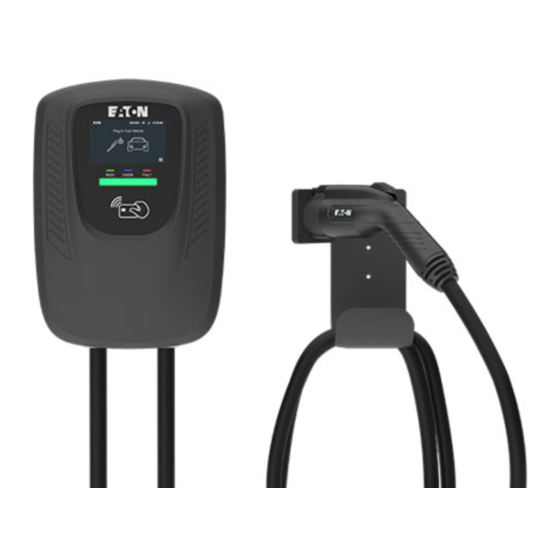
Installation Guide Product introduction Eaton Green Motion chargers (AC Level 2) deliver fast and cost-effective charging for passenger vehicles and medium-duty trucks used for last mile delivery. Combining breakout capabilities for metering, control, integrated communications and access control with flexible installation options. -
Page 4: Routine Operation
Green Motion Fleet & Green Motion Building Routine operation READY CHARGE FAULT READY CHARGE FAULT State Color Blink Type Idle / Ready Green No Blink Vehicle connected Blue Medium Vehicle connected, EVSE ready Blue Long Vehicle charging state, EVSE not ready (1) -
Page 5: Installation
YOU CONTACT YOUR ELECTRIC UTILITY TO DISCONNECT POWER TO AN EXISTING LOADCENTER. THE LINE SIDE OF THE MAIN BREAKER IS ENERGIZED UNLESS POWER IS DISCONNECTED UPSTREAM. EATON WILL NOT ASSUME RESPONSIBILITY FOR PROPERTY DAMAGE OR PERSONAL INJURY RESULTING FROM MISUSE OF THE INFORMATION IN THIS PUBLICATION. -
Page 6: General Reference
Green Motion Fleet & Green Motion Building Definitions Americans with Disabilities Act requirements to consider for workplace charging installation EVSE—Electric Vehicle Supply Equipment . EVSE is a general term used for all of the equipment used to supply The ADA and workplace charging electricity to the car . -
Page 7: A - Preparing The Ev Charger(S)
Recommended screw torque is 1 .0 N .m (9 .6 lbf .in) Reference: 1. EV charger front cover Repeat Steps A-1 through A-4 if you plan to install a second charger onto a pedestal GREEN MOTION FLEET & BUILDING www.eaton.com... -
Page 8: B Mount An Ev Charger To A Wall
Eaton suggests following the appropriate ADA installation guidelines for commercial applications CAUTION: Ensure the EV charger’s dedicated 100A upstream breaker handle is in the OFF position. Eaton recommends use of a BRX2100 circuit breaker to energize EV charging systems . Mount an EV charger to a wall... - Page 9 3. 1” trade size conduit Follow local guidelines to secure the cover and knock-out holes of the junction box. Reference: 1. Lineside conductors 2. Junction box 3. Conductors from circuit breakers 4. Junction box cover GREEN MOTION FLEET & BUILDING www.eaton.com...
- Page 10 Green Motion Fleet & Green Motion Building Steps B-6 and B-7 are optional: RJ45 (Ethernet) cable wiring B6 Main STEP B-6 Optional Assemble the custom Ethernet adapter connector (1), the 1/2” o-ring (2), and the 1/2” NPT conduit straight adapter (3) together as a unit .
-
Page 11: C Mount An Ev Charger To A Pedestal
1. Middle rear cover panel Reference: 2. Hex head screw assembly 1. Hex head screw assembly - x4 3. Top rear cover panel 2. Front NEMA plug 4. Bottom rear cover panel 3. Front NEMA plug GREEN MOTION FLEET & BUILDING www.eaton.com... - Page 12 Green Motion Fleet & Green Motion Building STEP C-3 Remove the serrated flange nuts and neoprene washers (1) from the cord hook (2) that came with the EV pedestal . With that hardware, install the premium cord holster (3) onto the pedestal using 1/4-20 hex head bolts, washers, and serrated flange nuts .
- Page 13 1" conduit locknut (2) . Insert the conduit assembly (3) into the pedestal and connect the locknut (2) to it . Reference: 1. Lineside conductors 2. 1” conduit locknut 3. Conduit assembly GREEN MOTION FLEET & BUILDING www.eaton.com...
- Page 14 Green Motion Fleet & Green Motion Building B6 Main Steps C-7 through C-9 are optional: RJ45 (Ethernet) cable wiring STEP C-7 Optional Assemble the custom Ethernet adapter connector (1), a 1/2” o-ring (2), and the 1/2” NPT conduit straight adapter (3) together as a unit .
- Page 15 Polaris lugs (1) . stud (1) . Secure the ring terminal to the pedestal ground stud using a 1/4-20 serrated flange nut . GROUND Reference: Reference: 1. Polaris lugs 1. EV charger ground conductor GREEN MOTION FLEET & BUILDING www.eaton.com...
- Page 16 Green Motion Fleet & Green Motion Building If you are installing a second EV charger onto the same EV pedestal, then skip to Section D. STEP C-12 STEP C-13 Replace the three access panels BEFORE ENERGIZING WALL CHARGER, RE-CHECK ALL ELECTRICAL starting with the top panel .
-
Page 17: D Mount A Second Ev Charger To A Pedestal
C-11 to mount the second EV charger. Install the last bolt, washer, and nut (4) to the plate assembly . Reference: 1. Adapter plate 2. Pedestal 3. Speed screws - x10 4. Hex bolts, washers, nut GREEN MOTION FLEET & BUILDING www.eaton.com... - Page 18 Green Motion Fleet & Green Motion Building STEP D-4 STEP D-5 Attach the premium cord holster (1) to the middle BEFORE ENERGIZING WALL CHARGER, RE-CHECK access cover (2) using the 1/4-20 hex head bolts, ALL ELECTRICAL CONNECTIONS AFTER ALL washers, and locknuts (3) .
-
Page 19: Fcc
. If the unit requires servicing, Operation is subject to the following two conditions: please contact Eaton customer service . The installation, maintenance, and servicing of your EV charger must only 1. This device may not cause harmful interference, and be performed by qualified personnel in accordance with applicable local regulations . -
Page 20: Warranty Information
For all other Terms and Conditions of Sale, please refer to Eaton’s not in conformance with Seller’s recommendations, including as set forth in Selling Policy 25-000. -
Page 21: Troubleshooting
Refer to the EV charger product page for instructions on commissioning the to the CPO EV charger using Wi-Fi, Ethernet, or cellular and connecting to a CPO provider. Scan for more troubleshooting tips on various error codes. GREEN MOTION FLEET & BUILDING www.eaton.com... - Page 22 Eaton 1000 Eaton Boulevard Cleveland, OH 44122 United States Eaton .com © 2022 Eaton All Rights Reserved Eaton is a registered trademark. Printed in USA Publication No . IL191012EN All trademarks are property December 2022 of their respective owners.
Need help?
Do you have a question about the Green Motion Fleet and is the answer not in the manual?
Questions and answers