Table of Contents
Advertisement
Eaton
VORAD
AlwaysAlert
®
®
Eaton
VORAD
SmartCruise
®
®
Eaton
VORAD
BlindSpotter
®
®
AlwaysAlert
Helps Avoid Accidents
TM
Significantly reduces rear-end collisions.
Helps drivers maintain safe following distances.
Audible/visual alerts to dangerous
obstacles ahead in rain, snow, fog
and night conditions.
Continuous undistracted road monitoring
up to 500-feet ahead and around curves.
Visit our website www.VORAD.com for additional information.
™
™
™
VORAD = Vehicle Onboard RADar
A highly sophisticated radar-based system
that helps prevent front and side collisions.
Provides additional driver safety and
convenience with automated
cruise control.
BlindSpotter
- "Sees" what you can't.
TM
Reduces lane change/merge collisions.
Warns driver of obstacles in their blind spot.
Driver had constant visual alert when an object
is detected in the blind spot.
Audible and visual alerts activated with turn signal.
Or call 866-RV-VORAD (866-788-6723)
Installation Guide VOIG-0035 July 2005
SmartCruise
TM
Uses radar to automatically maintain a safe
cruise control following distance.
Electronically communicates with diesel engines
to match following speed with traffic flow.
Automatically engages the engine retarder when
engine braking is required to maintain safe
following distances.
Automatically returns to cruise set speed when
traffic clears.
Reduces Driver Fatigue
Advertisement
Table of Contents

Related Manuals for Eaton VORAD AlwaysAlert


Summary of Contents for Eaton VORAD AlwaysAlert
- Page 1 Eaton VORAD AlwaysAlert ® ® ™ Eaton VORAD SmartCruise ® ® ™ Eaton VORAD BlindSpotter ® ® ™ Installation Guide VOIG-0035 July 2005 VORAD = Vehicle Onboard RADar A highly sophisticated radar-based system that helps prevent front and side collisions.
- Page 2 Limitations of Collision Warning Systems The Eaton VORAD system is intended solely as an aid for an alert and conscientious driver. The system should be used in conjunction with side-view mirrors and other instrumentation to maintain safe operation. A vehicle equipped with the VORAD system should be operated in the same safe manner as if the VORAD system were not installed.
-
Page 3: Table Of Contents
Wiring Harness Connection to Vehicle Wiring ......................17 Vehicle Wiring Connections ............................18 Diagnostics Road Test Check-Out Procedure ..........................20 Appendix Connector Wiring ..............................22 Recommended Cable Termination Procedure ......................23 Eaton VORAD System Specifications ........................24 Reading Fault Codes - Troubleshooting ........................25... -
Page 4: General Information
SmartCruise - adaptive cruise control • BlindSpotter - side radar lane change assistant • EVIMS - Eaton VORAD information management/accident reconstruction data recorder Special Tools To perform installation, you will need: • PC with the Eaton Service Ranger Diagnostic Software •... -
Page 5: General Information
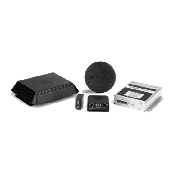
General Information General Information The VORAD System can be installed on a variety of vehicles. Typical applications include heavy class 8 trucks, medium duty trucks, transit and shuttle buses, RV motor homes, SUVs and passenger cars. The VORAD System components and locations are shown below: 1 - Antenna Assembly 4 - Central Processing Unit 2 - Side Sensor Display... -
Page 6: Side Sensor Display (Optional System Component)
General Information Side Sensor Display (optional system component) The side sensor display contains red and yellow indicator lights. The yellow indicator light is on when there is no object within the side sensor detection zone. When the side sensor detects an object, the red indicator light illuminates and the yellow indicator light goes off. -
Page 7: Component Installation
Component Installation Antenna Assembly Installation There are three antenna assembly mounting options to choose from (two surface and one recessed). To determine which will work best, review the options and note that there are seven installation holes and one cable pass-through hole required. -
Page 8: Surface - License Plate Mount
Component Installation Surface - License Plate Mount Attach mounting plate to license plate location. CAUTION Before drilling, check for any wiring, hoses and components that may be damaged by drilling and/or mounting hardware. Drill needed holes though template. Attach antenna assembly to mounting plate. Attach fairing over antenna assembly. -
Page 9: Surface - Front Facia Mount
Component Installation Surface - Front Facia Mount Locate mounting plate (template) at centerline above license plate and mark hole locations through template. CAUTION Before drilling, check for any wiring, hoses and components that may be damaged by drilling and/or mounting hardware. -
Page 10: Recessed - Mounted To Bumper/Facia From Behind Through Cutout
Component Installation Recessed - Mounted to Bumper/Facia from behind through Cutout CAUTION Before drilling, check for any wiring, hoses and components that may be damaged by drilling and/or mounting hardware. Measure antenna assembly at centerline of bumper and cut out shape in bumper. Determine which bracket configuration will work best and secure antenna assembly to bracket. -
Page 11: Antenna Assembly Alignment
Component Installation Antenna Assembly Alignment Note: Park the vehicle on a level surface. Vertical Alignment Adjust the antenna assembly to face down 0.50° from vertical. Use a digital level held against the face of the antenna assembly. Using a 5/32" Allen wrench, slightly loosen the four screws that attach the antenna assembly to its mounting brackets. -
Page 12: Horizontal Alignment
Component Installation Horizontal Alignment The antenna assembly must face straight ahead (azimuth) to detect objects out to maximum range traveling in the same lane as the VORAD-equipped vehicle. Select two vehicle reference points on the vehicle centerline that are identical and symmetrical. Ensure that the reference points are equally aligned. -
Page 13: Cpu Installation
Component Installation CPU Installation Central Processing Unit (CPU) Installation The CPU may be mounted in a variety of locations, such as under the dashboard, seat, or in the storage compartment. The location must be away from elements; such as water. Pick a location that will facilitate easy routing of the main wir- ing harness to the other components. -
Page 14: Driver Display Installation
Component Installation Driver Display Installation Install the Driver Display where the driver can easily view and adjust the controls. Usually it will be on top of the dash- board, flush with the front edge. For a more finished look, the display can be mounted in the dash, using the dash bezel. Consider the method chosen for routing the wiring harness to the Driver Display when determining the optimal location, but ease of operation and visibility of the driver display unit front panel are the primary considerations. -
Page 15: Driver Display Installation Procedure - In Dash
Component Installation Driver Display Installation Procedure - In Dash Use bezel as a template tracing the outer and inner side of the bezel face on the area of dash to be cut. Cut the dash between the two lines. Attach bezel to display and snap into cutout. 1 - Dashboard 4 - Screws (qty. -
Page 16: Side Sensor Display Installation
Component Installation Side Sensor Display Installation Install the side sensor display where the driver can easily see it. Usually, this will be on the windshield pillar of the vehi- cle, generally in the same line of sight as the side mirror, so that the driver can monitor both at the same time. If possi- ble, use existing hardware on the windshield pillar to secure the side sensor display bracket. -
Page 17: Side Sensor Installation
Component Installation Side Sensor Installation Install the side sensor where it provides maximum coverage of the driver's most vulnerable blind spot. The blind spot should be determined manually. Have an assistant walk from the front to the rear of the vehicle and mark on the ground where the driver loses sight of the assistant and then regains sight of the assistant as he or she continues to the rear of the vehicle. -
Page 18: Side Sensor Installation Procedure
Component Installation Side Sensor Installation Procedure Use a 5-1/2" hole saw to cut a hole for the sensor. Insert the sensor from the front. Attach using the supplied bracket and three stainless steel nuts. 1 - Side sensor 3 - Side of coach 2 - Bracket 4 - Cutout hole Multiple Side Sensors... -
Page 19: Wiring Harness Installation
Component Installation Wiring Harness Installation Installation of the wiring harness should start from the CPU and then extend outward to the other components. CAUTION Avoid routing the wiring harness near sharp edges or extreme heat, which could damage wire insulation. Route the wires along existing wires, up through existing pass-through holes or spaces in the floor or dashboard to the installed components. -
Page 20: Wiring Harness Connection To Vehicle Wiring
Component Installation Wiring Harness Connection to Vehicle Wiring Use the Butt connectors provided in this kit to connect the system wires to the existing vehicle wires (see Connector Wiring). Parts: Terminal, P/N 2B-14, Thomas & Betts® Solder sleeve, P/N CWT-3805, Raychem® Shrink tubing 5/16 Cut the vehicle wire and slide a solder sleeve over the wire that will remain single. -
Page 21: Vehicle Wiring Connections
Component Installation Vehicle Wiring Connections Brake Connect the wire marked “BRAKE” to the vehicle harness. Tap into the brake circuit so that current is sensed only when the vehicle brakes are applied. Power Connect the wire marked “IGNITION,” with the fuse holder, to an ignition switched power source so that the VORAD will only power up, when the ignition switch is turned to the run position. - Page 22 FCC Feild Office or to the Federal Communications Commission; Field Operations Bureau; 1919 W. St. NW; Room 734, Mail Stop 1500; Washington, D.C. 20554-0001. Manufactured by EATON VOARD Technologies, San Diego, California Made in U.S.A. Terminating J-1939/11 data link...
-
Page 23: Diagnostics
Calibrating the Discrete Speed Source Note: Calibration is not required when using J1587 or J1939 as the speed source. Use the calibration function on the Alignment Program supplied by Eaton. Press Speedcal and follow procedure. This tool checks the alignment of the VORAD antenna. - Page 24 Diagnostics Dynamic Antenna Alignment Procedure Use Alignment Program supplied by Eaton. Press Start and follow procedure. This tool checks the alignment of the VORAD antenna. Alignment should be made to within 0.5 degrees. A straight road is required. 1. Speed - recommend highway speed 50-65 MPH 2.
-
Page 25: Appendix
Ground (3) Ground (A) Brown Grey Lt Turn Signal Input Rt Turn Signal Input Dk Green Dk. Green Signal (4) Signal (4) EATON VORAD EATON VORAD View Looking Into EATON VORAD EATON VORAD the Connector Pins LEFT SENSOR RIGHT SENSOR... -
Page 26: Recommended Cable Termination Procedure
Appendix Recommended J1939 Cable Termination Procedure Remove cable outer jacket approximately 25 mm. Remove foil shield from exposed wires to within 2 mm of cable jacket. Strip insulation from data wires 7 ±0.8 mm. Attach adhesive filled solder sleeve and wire to drain wire per manufacturers recommendation OR attach extended wire barrel socket contact to the drain wire. -
Page 27: Eaton Vorad System Specifications
Appendix Eaton VORAD System Specifications DESCRIPTION VALUE Vehicle Closing Rate 0.25-106 m.p.h., 0.4-168 km/hr. Operating Range 1-500 feet, 0.3-157 meters (typical) Host Vehicle Speed 0.5-156 m.p.h., 0.8-250 km/hr. Power Requirements 12 to 24 Vdc, 20 watts (nominal) Operating Frequency Antenna Assembly 24.725 Ghz... -
Page 28: Reading Fault Codes - Troubleshooting
Appendix Reading Fault Codes - Troubleshooting Faults are logged in the system memory as fault codes. A complete listing of these fault codes is provided in the Fault Code Table. If the "FAIL" light remains on after start up: Set the range knob to the minimum level. Note: Inactive faults are displayed if the range knob is in the 1/2 to full range position. - Page 30 Eaton VORAD Copyright Eaton Corporation, 2004. EATON CORPORATION hereby grants its customers, vendors, or distributors permission to 13100 E. Michigan Avenue freely copy, reproduce and/or distribute this document in printed Galesburg, MI 49053 format. THIS INFORMATION IS NOT INTENDED FOR SALE OR U.S.A.
Need help?
Do you have a question about the VORAD AlwaysAlert and is the answer not in the manual?
Questions and answers