
Subscribe to Our Youtube Channel
Related Manuals for Eaton EZD Series


Summary of Contents for Eaton EZD Series
- Page 1 EZD Series User Manual April 2005 MN05013005E For more information visit: www.EatonElectrical.com...
- Page 3 Warning! Dangerous electrical voltage! Before commencing the installation • Disconnect the power supply of the device. • Connecting cables and signal lines should be installed so that inductive or capacitive • Ensure that devices cannot be accidentally interference does not impair the automation restarted.
- Page 4 • Emergency stop devices complying with • Measures should be taken to ensure the IEC/EN 60204-1 must be effective in all proper restart of programs interrupted after operating modes of the automation devices. a voltage dip or failure. This should not Unlatching the emergency-stop devices cause dangerous operating states even for must not cause restart.
-
Page 5: Table Of Contents
Contents About This Manual Device designation Writing conventions Target readership Proper use – Improper use Overview Device overview – EZD devices at a glance – Type references for the EZD EZD operation – Buttons – Moving through menus and choosing values –... - Page 6 Connecting the inputs – Connecting the AC inputs – Connecting EZD-DC inputs Connecting the outputs Connecting relay outputs – EZD-R.. – EZ6..-..RE.. – EZ2..-RE Connecting transistor outputs – EZD-T.. – EZ6..-DC-TE Connecting analog outputs – Connecting servo valves – Setpoint entry for a drive Connecting the NET network –...
- Page 7 – Displaying the Status display of other stations Configuring the interface for the COM-LINK mode 102 – Setting up the COM-LINK Terminal mode – Terminal mode Programming wiring diagrams with EZD EZD operation – Buttons for drawing circuit diagrams and function block usage –...
- Page 8 – Comparators – Text output function block – Data function block – PID controller – Signal smoothing filter – GET, fetch a value from the network – Seven-day time switch – Year time switch – Value scaling – Jumps – Master reset –...
- Page 9 – Password logout – Set variable to fixed value – Increment variable – Decrement variable – Changeover relay EZ-NET Network, COM-LINK Serial Connection 333 Introduction to EZ-NET EZ-NET network topologies, addressing and functions – Loop through the unit wiring method –...
- Page 10 – Adjustable parameters for function blocks Setting date, time and daylight saving time Changing between winter/summer time (DST) Activating input delay (debounce) – Deactivating debounce (input delay) Activating and deactivating the P buttons – Activating the P buttons – Deactivating the P buttons Startup behavior –...
- Page 11 – Interface – Memory card – EZSoft Device version Appendix Technical data – General – CPU, real-time clock/timing relay/memory – Transistor outputs – Analog output – EZ-NET network List of the function blocks – Function blocks – Function block coils –...
-
Page 13: About This Manual
About This Manual This manual describes the installation, commissioning and programming (circuit diagram generation) of the EZD control relay. A specialist knowledge of electrical engineering is needed for commissioning and creating circuit diagrams. When active components such as motors or pressure cylinders are controlled, parts of the system can be damaged and persons put at risk if the EZD device is connected or programmed incorrectly. - Page 14 About This Manual Indicates interesting tips and additional information For greater clarity, the name of the current chapter is shown in the header of the left-hand page and the name of the current section in the header of the right-hand page. This does not apply to pages at the start of a chapter and empty pages at the end of a chapter.
-
Page 15: Ezd
EZD must only be installed and wired up by trained Target readership electricians or other persons familiar with the installation of electrical equipment. A specialist knowledge of electrical engineering is needed for commissioning and creating circuit diagrams. When controlling active components such as motors or pressure cylinders, parts of the system can be damaged and persons put at risk if EZD is connected or programmed incorrectly. -
Page 16: Overview
EZD is an electronic HMI unit and control relay with the Overview following features: • Logic functions, • Timing relay and counter functions, • Time switch functions, • Arithmetic functions, • PID controllers, • Operator and display functions. EZD is a display, HMI, control and input device in one. With EZD you can create solutions for domestic applications as well as for tasks in machine and plant construction. - Page 17 Overview – off-delayed with random switching, – on and off delayed, – on and off delayed with random switching, – single pulse, – synchronous flashing, – asynchronous flashing. • use up and down counters, • count high-speed signals: – up and down counters with upper and lower limit values, –...
-
Page 18: Device Overview
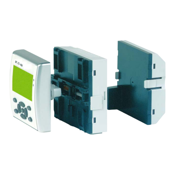
• track the flow of current in the circuit diagram, • load, save and password-protect circuit diagrams. If you prefer to wire up EZD from a PC, then use EZSoft. EZSoft allows you to create and test your circuit diagram on the PC. - Page 19 Device overview Power supply and CPU Figure 2: Device overview of power supply and CPU Power supply EZ-NET terminals EZ-LINK terminal Interface for memory card, PC and point-to-point connection Power supply / operating mode LED EZ-NET LED Inputs/outputs Figure 3: Device overview of inputs/outputs Inputs Analog output (optional)
-
Page 20: Type References For The Ezd
Type references for the EZD EZD - x xx x - x x - x x Additional functions Equipment B = Operator buttons ME = Open-loop control, closed-loop control; NT = Open- loop control, closed-loop control, EZ-NET Device function Number = display and enclosure in mm CP8 = Power supply and CPU rating 8 R = relay outputs, T = Transistor outputs A = Analog output... -
Page 21: Moving Through Menus And Choosing Values
EZD operation Moving through menus and choosing values Show System menu Go to next menu level Select menu item Activate, modify, save your entry Return to last menu level Cancel your entry since the last OK Í Ú Change menu item Change value ú... -
Page 22: Selecting Main And System Menu
Selecting main and system menu Status display I .2..5..MO 02:00 Q..34 . STOP S .2 6.. password Current selection PROGRAM... SECURITY... STOPå RUN SYSTEM... flashes in PARAMETERS MENU LANGUAGE the EZD menu SET CLOCK... CONFIGURATOR... 1st menu level 1st menu level Main menu System menu Date display... -
Page 23: Status Display For Local Expansion
EZD operation Status display for local expansion Inputs AC expansion ok/P buttons R 1..12 Expansion or Weekday/Date Weekday/Time MO 10:42 S 1..8 STOP Outputs On: 1, 2, 3, 4/Off:… RS = Expansion functioning correctly EZD advanced Status display I 12...6.89..12 I NT1 AC P- Retention/debounce/ AC expansion ok/P buttons... - Page 24 Table 1: Power supply/RUN-STOP mode LED LED OFF No power supply LED continuously lit Power supply present, STOP mode LED flashing Power supply present, RUN mode Table 2: EZ-NET LED (EZ-NET) LED OFF EZ-NET not operational, fault, in configuration LED continuously lit EZ-NET is initialized and no station has been detected.
-
Page 25: Menu Structure
EZD operation Menu structure Main menu without password protection You access the main menu by pressing OK. STOP: Circuit diagram display RUN: Power flow display Main menu PROGRAM... Æ PROGRAM... CIRCUIT DIAGRAM Circuit diagram STOP å RUN DELETE PROGRAM FUNCTION RELAYS PARAMETERS CARD SET CLOCK... - Page 26 Main menu PROGRAM... DELETE PROGRAM CARD... DEVICE-CARD REPLACE ? CARD-DEVICE DELETE CARD ? PROGRAM... Æ DEVICE-CARD STOP å CARD-DEVICE REPLACE ? PARAMETERS DELETE CARD ? SET CLOCK... æ TERMINAL MODE DEVICE-CARD CARD-DEVICE DELETE ? DELETE CARD ? Parameter display PROGRAM... Æ...
- Page 27 EZD operation Main menu with password protection Four wrong entries Unlocking Main menu Password entry (if enabled) PASSWORD... Æ DELETE ALL Password STOP å PARAMETERS SET CLOCK... æ Correct entry Status display PASSWORD... EZD system menu The System menu is accessed by simultaneously pressing DEL and ALT.
- Page 28 System menu SECURITY... DEBOUNCE å Æ DEBOUNCE å Æ SYSTEM... P BUTTONS P BUTTONS å MENU LANGUAGE RUN MODE RUN MODE å CONFIGURATOR... CARD MODE æ CARD MODE å æ TERMINAL MODE TERMINAL MODE å DISPLAY... DISPLAY... RETENTION... RETENTION... INFORMATION... INFORMATION...
- Page 29 EZD operation System menu SECURITY... ENGLISH Æ SYSTEM... DEUTSCH å MENU LANGUAGE FRANCAIS CONFIGURATOR... ESPANOL æ Only one selection is possible. ITALIANO PORTUGUES NEDERLANDS SVENSKA POLSKI TURKCE SECURITY... NET PARAMETERS... NET... SYSTEM... STATIONS... COM... MENU LANGUAGE CONFIGURE... LINK... CONFIGURATOR... The other menus of NET and COM are only shown in STOP mode...
- Page 30 System menu This list is only created NET PARAMETERS... Æ in Station 1. STATIONS... This list only appears if CONFIGURATOR... æ station 1 has been selected. SAVE Æ æ CANCEL Æ æ NET PARAMETERS... STATIONS... CONFIGURE? CONFIGURATION CONFIGURATOR... PROGRESS. Fault scenario ERR: ID CONFLICT with ID conflict.
-
Page 31: Selecting Or Toggling Between Menu Items
EZD operation System menu BAUDRATE:19200B NET... BAUDRATE: 9600B COM-LINK å COM... COM-LINK REMOTE MARKER... CONFIGURE... REMOTE MARKER... BAUDRATE:19200B READ: COM-LINK å 1MD00 1MD00 REMOTE MARKER... WRITE: 1MD00 1MD00 This menu only appears if COM-LINK was selected. Selecting or toggling between menu items Í... -
Page 32: Cursor Display
Cursor display The cursor flashes. HH:MM '4:23 DD.MM 05.05 Ê Full cursor YEAR 2003 ú í • Move cursor with Í Ú • in circuit diagram also with Value HH:MM 14:23 ú í DD.MM 05.05 • Change position with YEAR 2003 Í... -
Page 33: Installation
Installation The EZD must only be installed and wired up by qualified electricians or other persons familiar with the installation of electrical equipment. Danger of electric shock! Never carry out electrical work on the device while the power supply is switched on. Always follow the safety rules: •... - Page 34 Installation When using the EZD with expansion units, connect the expansion concerned before mounting (see page 47). For ease of wiring, leave a gap of at least 30 mm between the EZD terminals and the wall or adjacent devices. Figure 4: Clearances to the EZD Fitting the protective membrane For special applications such as in the food industry, the...
- Page 35 Mounting Figure 5: Fitting the protective membrane Protective membrane Display/operating unit Place the protective membrane over the display/operating unit. Caution! Ensure that the membrane fits snugly in the groove of the display/operating unit. Otherwise a proper seal cannot be guaranteed and particles may enter underneath the membrane.
- Page 36 Installation Figure 6: Correct position of the protective membrane If the protective membrane has to be replaced, the display and the operating unit have to be removed. Replace the membrane and refit the device. Mounting the protective cover The protective cover is provided for using the device in aggressive environments.
- Page 37 Mounting Figure 7: Removing the front frame Remove the front frame as shown in the figure. The protective cover can be mounted in two different positions. Choose the position that is most suitable for the application at hand and your requirements. Figure 8: Position of the protective cover MN05013005E...
- Page 38 Installation Figure 9: Mounting the protective cover Mount the protective cover as shown in the figure. Sealing the protective cover Figure 10: Sealing the protective cover The grip handle of the protective cover is provided with holes that can be used in any mounting position. You can fit a wire or similar material through these holes in order to seal the cover.
- Page 39 Mounting Mounting the display/operating unit, “front mounting” 22.5 Figure 11: Drill holes for the EZD Drill and punch out two 22.5 mm diameter holes. The diameter is the same as is normally required for control circuit devices. Observe the following technical requirements: •...
- Page 40 Installation Figure 12: Mounting the display/operating unit The protective membrane or the protective cover must be fitted. Fit the display/operating unit in the punched fixing holes. For more information visit: www.EatonElectrical.com MN05013005E...
- Page 41 Mounting Figure 13: Screw fastening the display/operating unit Screw fasten the display/operating unit. The tightening torque must be between 1.2 and 2 Nm (10.6 and 17.6 in.lb) Ensure that the correct torque is used. If the tightening torque is too low or high, this may impair the seal. Figure 14: Mounting the display/operating unit, front mounting Use the combination box spanner with the designation M22-MS.
- Page 42 Installation Removing the display/operating unit, “front mounting” Unscrew the fixing element and remove the display/ operating unit. Mounting the power supply/CPU module If you wish to add expansion units to the power supply/CPU module, the top-hat rail must be fitted beforehand. Fitting the top-hat rail Ensure that the cutout of the top-hat rail was prepared for the fixing shafts according to the specified dimensions.
- Page 43 Mounting Caution! The fixing shafts of the display/operating unit are designed for mounting the expansion units. Other devices such as contactors must not be mounted on this top-hat rail. Attach the expansion unit before fitting the top-hat rail. Figure 16: Fitting the top-hat rail Fit the top-hat rail in the groove using the slide catch of the power supply/CPU module and the expansion unit.
- Page 44 Installation Figure 17: Fitting the CPU with and without top-hat rail For more information visit: www.EatonElectrical.com MN05013005E...
- Page 45 Mounting Mounting the inputs/outputs onto the power supply/CPU module Figure 18: Plugging in the I/O module The inputs/outputs can be mounted before or after mounting the power supply/CPU module onto the fixing shaft. Figure 19: CPU with I/O module MN05013005E For more information visit: www.EatonElectrical.com...
- Page 46 Installation Removing the inputs/outputs Figure 20: Releasing the I/O module Press the two catches together. Pull one side out of the catch. Pull the other side out of the second catch. Figure 21: Removing the I/O module Remove the I/O module. For more information visit: www.EatonElectrical.com MN05013005E...
- Page 47 Mounting Removing the power supply/CPU module The power supply/CPU module can be removed with or without the I/O module. If there is another fixing point for the top-hat rail, apart from the one for the display/operating unit, undo it. Figure 22: Releasing the fixing shaft Use a screwdriver with a 100 x 3.5 mm slot width.
- Page 48 Installation Figure 23: Removing the spring Remove the spring with a screwdriver. Figure 24: Pulling out and removing the slide catch Pull the slide catch out of the guide and remove it. For more information visit: www.EatonElectrical.com MN05013005E...
- Page 49 Mounting Hook the EZD to the top edge of the top-hat rail and hinge into place while pressing down slightly. Press down lightly on both the device and the top-hat rail until the unit snaps over the lower edge of the top-hat rail. The EZD will clip into place automatically.
- Page 50 Installation Figure 26: Screw mounting for the EZD EZ2..-..: EZ700: Figure 27: Screw mounting for EZ For more information visit: www.EatonElectrical.com MN05013005E...
-
Page 51: Connecting The Expansion Unit
Connecting the expansion unit Connecting the expansion unit Figure 28: Connecting expansion units Terminals Tool for cage clamp terminals Slot-head screwdriver, width 3.5 × 0.6 mm. Connection cross-sections of the EZD cage clamp terminal cables • Solid: 0.2 to 4 mm (AWG 24 -12) •... -
Page 52: Network Cables And Plugs
Installation If possible use the prefabricated EZ-NT cables (e.g. 30 or 80 Network cables and plugs cm). Other cable lengths can be made using the EZ-NT-CAB cable and the EZ-NT-RJ45 plug. AWG 24, 0.2 mm are the largest crimpable cross-sections. The first and last stations in the network must be provided with an EZ-NT-R bus termination resistor. - Page 53 Connecting the power supply EZD-AC power supply Figure 29: AC power supply on the EZD Attention! A short current surge will be produced when switching on for the first time. Do not switch on AC via Reed contacts since these may burn or melt. MN05013005E For more information visit: www.EatonElectrical.com...
- Page 54 Installation EZ…-AC-.E expansion units E+ E- 115/230 V Figure 30: Power supply on the AC expansion units Attention! A short current surge will be produced when switching on for the first time. Do not switch on EZ AC via Reed contacts since these may burn or melt.
- Page 55 Connecting the power supply EZD-DC power supply L01+ L02+ L01– > 1 A +24V 0V 0V Figure 31: Power supply on the EZD The EZD power supply/CPU module supplies the necessary power supply to itself, the display, the input/output electronics, the EZ-LINK, and optionally the EZ-NET.
-
Page 56: Cable Protection
Installation EZ…-DC-.E DC expansion units L01+ L01- E+ E- 24 V Figure 32: Power supply on the DC expansion units EZ DC is protected against polarity reversal. To ensure that EZ works correctly, ensure that the polarity of each terminal is correct. -
Page 57: Connecting The Inputs
Connecting the inputs EZ or EZD inputs switch electronically. Once you have Connecting the inputs connected a contact via an input terminal, you can reuse it as a contact in your EZD circuit diagram as often as you like. +24 V Figure 33: Connecting the inputs Connect contacts such as pushbutton actuators or switches to EZ or EZD input terminals. - Page 58 Installation EZD-AC basic unit Figure 34: Connecting the inputs Warning! The AC inputs must only be used with EZD-AC-CP8... devices. Other devices may be destroyed. For more information visit: www.EatonElectrical.com MN05013005E...
- Page 59 Connecting the inputs AC expansion device E+ E– R11 R12 115/230 V h Figure 35: Inputs on the EZ…-AC-.E expansion device Connect the inputs, for example, to pushbutton actuators, switches or relay/contactor contacts. Input signal voltage range • OFF signal: 0 to 40 V •...
- Page 60 Installation The following applies to expansion units: With longer cables, connect a diode (e.g. 1N4007) for 1 A, minimum 1 000 V reverse voltage, in series to the EZ input. Ensure that the diode is pointing towards the input as shown in the circuit diagram, otherwise EZ will not detect the 1 state.
- Page 61 Connecting the inputs Increasing the input current The following input circuit can be used in order to prevent interference and also when using two-wire proximity switches: 100 nF/275 V h E+ E– R11 R12 115/230 V h Figure 37: Increasing the input current When using a 100 nF capacitor, the drop-out time of the input increases by 80 (66.6) ms at 50 (60) Hz.
-
Page 62: Connecting Ezd-Dc Inputs
Installation Complete devices for increasing the input current are available under the type reference EZ256-HCI. E+ E– R11 R12 115/230 V h Figure 39: EZ600 with EZ256-HCI The increased capacitance increases the drop-out time by approx. 40 ms. Connecting EZD-DC inputs Use input terminals I1 to I12 to connect pushbutton actuators, switches or 3 or 4-wire proximity switches. - Page 63 Connecting the inputs L01+ L02+ L01– > 1 A +24V 0V 0V I3 I4 I5 I6 I7 I8 I9 I10 I11 I12 Figure 40: EZD-DC The digital inputs must have the same voltage as the power supply of the EZD. L01 + L01 –...
- Page 64 Installation Connecting analog inputs Inputs I7, I8, I11 and I12 can also be used to connect analog voltages ranging from 0 V to 10 V. The following applies: • I7 = IA01 • I8 = IA02 • I11 = IA03 •...
- Page 65 Connecting the inputs The following circuits contain examples of applications for analog value processing. Ensure that the reference potential is connected. Connect the 0 V of the power supply unit for the different setpoint potentiometers and sensors shown in the examples to the 0 V terminal of the EZD power feed.
- Page 66 Installation Temperature sensor, brightness sensor, 20 mA sensor L01+ L02+ L01– > 1 A +12 V +24 V H 0...10 V –35...55 ˚C 4...20 mA 0...10 V 500 O +24V 0V 0V I3 I4 I5 I6 I7 I8 I9 I10 I11 I12 Figure 43: Temperature sensor, brightness sensor, 20 mA sensor...
- Page 67 Connecting the inputs Connecting high-speed counters and frequency generators High-speed counter signals on the EZD can be counted correctly on inputs I1 to I4 independently of the cycle time. L01+ L02+ L01– > 1 A I8 I9 I10 I11 I12 +24V 0V 0V Figure 44: High-speed counter, frequency generator MN05013005E...
-
Page 68: Connecting The Outputs
Installation Connecting incremental encoders Inputs I1, I2 and I3, I4 on the EZD can each be used for the high-speed counting of an incremental encoder independently of the cycle time. The incremental encoder must generate two 24 V DC square wave signals with a 90° phase shift between them. -
Page 69: Connecting Relay Outputs
Connecting relay outputs The relay or transistor outputs are used to switch loads such as fluorescent tubes, filament bulbs, contactors, relays or motors. Check the technical thresholds and output data before installing such devices (see chapter “Technical data”, from Page 407). Connecting relay outputs EZD-R.. -
Page 70: Ez6
Installation EZ6..-..RE.. 24 V H 8 A 10 000 000 115 V h 8 A 230 V h 8 A 1000 W 0 V H, N 10 x 58 W 25 000 F 8 A/B 16 L1, L2, L3 (115/230 V h) + 24 V H Figure 48: EZ6..-..-RE.. -
Page 71: Connecting Transistor Outputs
Connecting transistor outputs Connecting transistor EZD-T.. outputs + 24 V H 24 V H 0.5 A 0.5 A (20.4 – 28.8 V H) 5 W/24 V F 10 A 24 V Figure 50: EZD-T.. transistor outputs EZ6..-DC-TE 24 V F 10 A 0 V H f 2.5 A + 24 V H... - Page 72 Installation Parallel connection: Up to four outputs can be connected in parallel in order to increase the power. The output current will increase in this case to a maximum of 2 A. Caution! Outputs may only be connected in parallel within a group (Q1 to Q4 or Q5 to Q8, S1 to S4 or S5 to S8), such as Q1 and Q3 or Q5, Q7 and Q8.
-
Page 73: Connecting Analog Outputs
Connecting analog outputs Behavior with short-circuit/overload Should a short-circuit or overload occur on a transistor output, this output will switch off. The output will switch on up to maximum temperature after the cooling time has elapsed. This time depends on the ambient temperature and the current involved. -
Page 74: Connecting Servo Valves
Installation Connecting servo valves L01+ L02+ L01– > 1 A +24V 0V 0V I8 I9 I10 I11 I12 0V 0V QA 1 Figure 53: Connecting servo valves Setpoint entry for a drive L01+ L02+ L01– > 1 A 0V IA +24V 0V 0V I8 I9 I10 I11 I12 0V... -
Page 75: Connecting The Net Network
Connecting the NET network EZD with network connection (EZD-CP.-NT) can be used for Connecting the NET creating the NET network. Up to eight devices can be network connected to this network. Further information can be found in the Chapter “EZ-NET Network, COM-LINK Serial Connection”, Page 333. -
Page 76: Cable Length And Cross-Sections
Installation Table 5: Prefabricated cables, RJ45 plug on both ends Cable length Type designation EZ-NT-30 EZ-NT-80 EZ-NT-150 Material for self-manufactured cables 100 m 4 × 0.18 mm : EZ-NT-CAB Bus termination resistor The first and last stations in the network must be provided with a bus termination resistor. - Page 77 Connecting the NET network Calculating the cable length with known cable resistance If the resistance of the cable per unit of length is known (resistance per unit length ' in Ω/m), the entire cable resistance must not exceed the following values. depends on the selected baud rates: Baud rate Cable resistance R...
-
Page 78: Plugging And Unplugging Network Cables
Installation Calculating length with known cable cross-section The maximum cable lengths are calculated for a known conductor cross-section = cable length in m = minimum cable cross-section in mm = resistivity of copper, if not otherwise stated 0.018 Ω ρ S ×... - Page 79 Connecting the NET network R 1 - 12 S 1 - 8 I 1 - 12 R 1 - 12 Q 1 - 6 S 1 - 6 AS-Interface + – I 1 - 12 Q 1 - 8 Figure 57: Bus termination resistors First station on the NET network Bus termination resistor Last station on the NET network...
-
Page 80: Connecting The Serial Interface
Installation Figure 58: Plugging and unplugging cables The EZD power supply/CPU module is provided with a multi- Connecting the serial function interface. This can be used to set up point-to-point interface communication between different devices. The interface is also used for connecting EZSoft. The following device configurations are possible: •... - Page 81 Connecting the serial interface Figure 59: Fitting/removing the interface cover Remove the interface cover or other plugs from the interface. Fit the connectors in the devices. MN05013005E For more information visit: www.EatonElectrical.com...
- Page 82 06/04 AWB2528-1480GB Figure 60: Fitting the connection plug It must be ensured in all circumstances that the connector with the marking POW-Side is fitted in the interface of the EZD device. The serial interface only functions if the EZD device is providing the power feed required for the interface cable.
-
Page 83: Expanding Inputs/Outputs
Expanding inputs/outputs POW-Side Figure 61: Point-to-point serial interface You can add expansion units to all EZD types with an EZ-LINK Expanding inputs/outputs connection in order to increase the number of inputs and outputs: Expandable EZ basic Expansion units units EZD-CP8-.. EZ618-..-RE •... - Page 84 Installation Connect the EZ expansion unit via the EZ-LINK-DS plug connector. EZ-LINK-DS EZD-CP8.. EZ6..-..-RE.. EZ6..-..-TE.. EZ2… Figure 62: Connecting local expansion units with EZD-CP8.. The following electrical separation is implemented between the power supply/CPU module of the EZD device and the expansion unit (separation always in local connection of expansion unit) •...
-
Page 85: Remote Expansion
Expanding inputs/outputs Remote expansion Remote expansion units can be installed and run up to 30 m away from the basic unit. Warning! The two-wire or multiple-wire cable between the devices must adhere to the insulation voltage requirement which is stipulated for the installation environment. Otherwise, a fault (ground fault, short-circuit) may lead to the destruction of the units or injury to persons. -
Page 87: Commissioning
Commissioning Before startup check whether the power supply, inputs, Switching on outputs, the serial interface and the EZ-NET connection are properly connected: • 24 V DC version: – Terminal +24 V: +24 V voltage – Terminal 0 V: 0 V voltage –... -
Page 88: Ezd Operating Modes
Commissioning Press OK to confirm your choice and press ESC to exit the menu. EZ will then switch to the Status display. You can change the language setting at a later time, if you wish, see Section “Changing the menu language”, Page 364. -
Page 89: Creating Your First Circuit Diagram
Creating your first circuit diagram The following single line diagram takes you step by step Creating your first circuit through wiring up your first circuit diagram. In this way you will diagram learn all the rules, quickly enabling you to use EZD for your own projects. - Page 90 Commissioning In the following example, EZD carries out all the wiring and performs the tasks of the circuit diagram shown below. L01+ L01– +24V 0V 0V I 01----I 02- --Ä Q 01 L01– Figure 65: Lamp controller with EZD For more information visit: www.EatonElectrical.com MN05013005E...
-
Page 91: Starting Point Status Display
Creating your first circuit diagram Starting point Status display When you switch on EZD, it opens the Status display I .... immediately to show the switching state of the inputs and outputs. It also indicates whether the EZD is already running MO 02:00 a program. -
Page 92: Circuit Diagram Display
Commissioning Circuit diagram display The circuit diagram display is currently empty. The cursor Ê flashes at the top left, which is where you will start to create your diagram. The location of the cursor is indicated in the status line. L: = L: 1 C:1 B:7944 Rung (line), C: = Contact or coil (contact), B: = Free memory available in bytes. -
Page 93: From The First Contact To The Output Coil
Creating your first circuit diagram From the first contact to the output coil With EZD, you work from the input to the output. The first input I 01 contact is Press OK. I 01 I 01 EZD proposes the first contact at the cursor position. -
Page 94: Wiring
Commissioning Wiring EZD displays a small arrow in the circuit diagram when creating the wiring. Press ALT to activate the wiring arrow cursor and use the Í Ú ú í cursor buttons to move it. ALT also has two other functions depending on the cursor position: •... - Page 95 Creating your first circuit diagram í Press the cursor button again. The cursor will move to the coil field. Press OK. --------Ä Q 01 Q 01 EZD inserts the relay coil . The specified coil function Ä Q 01 and the output relay are correct and do not have to be changed.
-
Page 96: Testing The Circuit Diagram
Commissioning Testing the circuit diagram Switch to the main menu and select the STOP RUN menu PROGRAM... option. STOP å RUN With a tick at RUN or STOP you switch to the RUN or STOP PARAMETERS operating modes. SET CLOCK... EZD runs in the mode indicated by the tick. - Page 97 Creating your first circuit diagram Press pushbutton actuator S2, that has been connected as a break contact. The rung is interrupted and relay Q1 drops out. I 01====I 02-------------------Ä Q 01 L: 1 C:1 RUN Figure 70: Power flow display: Input I1 is closed, input I2 is open, relay Q1 has dropped out = visible area Press ESC to return to the Status display.
- Page 98 Commissioning Press pushbutton actuator S2, that has been connected as a break contact. The rung is interrupted and relay Q1 drops out. â==#-------- # L: 001 I 01 Í Ú ú í Use the cursor buttons to move between the contacts or coil.
-
Page 99: Deleting The Circuit Diagram
Creating your first circuit diagram Deleting the circuit diagram Switch the EZD to STOP mode. EZD must be in STOP mode in order to extend, delete or modify the circuit diagram. Use PROGRAM… to switch from the main menu to the next menu level. -
Page 100: Configuring An Ez-Net Network
Commissioning If you want to work with the EZ-NET network and Configuring an EZ-NET communicate with several stations, the network must be network configured first. Proceed as follows: Connect all network stations. EZ-NET socket 2 to EZ-NET socket 1 . The first station 1 (socket 1 ) and the last station (socket 2 ) must be provided with a network termination resistor . -
Page 101: Entering The Network Station Number
Configuring an EZ-NET network The following tasks are only possible in STOP mode. Entering the network station number Simultaneously press the DEL and ALT buttons while EZ shows the Status display. The System menu appears SECURITY... SYSTEM... Select the CONFIGURATOR menu option. MENU LANGUAGE CONFIGURATOR... -
Page 102: Entering Network Stations
Commissioning Entering network stations Only the network station at physical location 1 with station number 1 has a station list. The left-hand column is the physical location. You can only assign a physical location to unused station numbers. Physical location 1 is permanently assigned to station number 1. -
Page 103: Configuring An Ez-Net Network
Configuring an EZ-NET network Configuring an EZ-NET network The EZ-NET network can only be configured from station 1. Requirement: All stations are correctly connected to the network and the termination resistors have been connected. All stations have a power supply and are in STOP mode. The POW LED is permanently lit. -
Page 104: Changing The Ez-Net Network Configuration
Commissioning Changing the EZ-NET network configuration The configuration of the EZ-NET network can be modified at any time at station 1, physical location 1. The NET parameters are modified as described for inputting parameters for the first time. Station addresses in the STATIONS menu are changed as follows: Go to the physical location which is to be modified. -
Page 105: Displaying The Status Display Of Other Stations
Configuring an EZ-NET network Displaying the Status display of other stations On every device with a display, you can display the states of the inputs and outputs of each network station. Change to the Status display and press the ESC button. 1I12.. -
Page 106: Configuring The Interface For The Com-Link Mode
Commissioning If you wish to set up point-to-point communication with Configuring the interface for another station, this can be done using either the serial the COM-LINK mode interface or EZ-NET. The EZD must be provided with a display and operating unit. The connection must be configured for this purpose (Page 348 Section “Introduction to COM-LINK”). -
Page 107: Setting Up The Com-Link
Configuring the interface for the COM-LINK mode to configure the stations which have an active power supply. Go to the EZD device that is the active station running the serial interface. The following tasks are only possible in STOP mode. Setting up the COM-LINK Caution! The EZD device can either run as a station on the EZ-NET... - Page 108 Commissioning The menu BAUDRATE: 9600B will appear. The two baud BAUDRATE: 9600B rates are for 9600 or 19200 baud. Select the baud rate that COM-LINK REMOTE MARKER... your connection will support. Baud rate selection. Select 19200 baud as the baud rate. Badly laid cables may give rise to electromagnetic interference.
- Page 109 Configuring the interface for the COM-LINK mode Press the OK button. READ: 1MD00 Ç 1MD00 The data is physically located in the second station, i.e. the WRITE: 1MD00 Ç 1MD00 remote station. The active station reads and writes data from and to the markers of the remote station.
- Page 110 Commissioning í Use the button to enter the upper limit of the READ READ: range. 1MD11 Ç 1MD14 Í WRITE: Use the button to select the value. 1MD00 Ç 1MD00 Confirm the entry with the OK button. READ: 1MD11 Ç 1MD14 WRITE: 1MD00 Ç...
-
Page 111: Terminal Mode
Terminal mode Terminal mode Terminal mode The EZD device also supports the TERMINAL MODE operating mode. This allows you to remotely control other devices. This is especially useful if the other device is located in an inaccessible place. Terminal mode can also be used to show the menus and displays of devices that do not have their own display or operating unit. - Page 112 Commissioning Terminal mode using the point-to-point serial interface POW-Side Figure 75: Terminal mode using the point-to-point serial interface For more information visit: www.EatonElectrical.com MN05013005E...
- Page 113 Terminal mode Terminal mode using the EZ-NET topology I 1 - 12 R 1 - 12 Q 1 - 6 S 1 - 8 I 1 - 12 R 1 - 12 Q 1 - 6 S 1 - 6 AS-Interface I 1 - 12 Q 1 - 8...
- Page 114 Commissioning I 1 - 12 Q 1 - 6 I 1 - 12 Q 1 - 8 Figure 77: Terminal mode in EZ-NET with two EZD devices The above topology allows two EZD devices to be run in EZ- NET Terminal mode. Each EZD device can run with the other devices in Terminal mode.
- Page 115 Terminal mode I 1 - 12 Q 1 - 6 POW-Side I 1 - 12 Q 1 - 6 I 1 - 12 Q 1 - 8 POW-Side Figure 78: Terminal mode in EZ-NET as well as via two serial interfaces The above topology is a combination of EZ-NET operation and serial interface operation.
- Page 116 Commissioning Caution! Data collision! In order to ensure proper operation, the following conditions must be observed. The following applies: If there is more than one EZD device in Terminal mode, each EZD device must access a different EZ-NET station. A device running in Terminal mode must not access any two devices communicating with each other in Terminal mode.
- Page 117 Terminal mode Select the second station. This station will control the display STATION ID: 0 and respond to the operating unit. START MODE Station ID: 0 = Station on the serial interface 1 = Station 1 EZ-NET 2 = Station 2 EZ-NET 3 = Station 3 EZ-NET 4 = Station 4 EZ-NET 5 = Station 5 EZ-NET...
- Page 118 Commissioning If the text “Connection establishment in progress...” is displayed for longer than 10 s, the connection to the selected device is faulty. Press ESC to cancel the selection. Rectify the fault. Try to re-establish the connection. The following applies if the device to be operated is in RUN mode and is displaying a screen: This screen is not displayed in Terminal mode.
- Page 119 Terminal mode In Terminal mode, the EZD device makes its display and operating unit available to the connected device. Only data for the display and the status of the buttons is sent via the connection. This ensures that the local data of the connected device is not destroyed in the event of a communication fault.
-
Page 121: Programming Wiring Diagrams With Ezd
Programming wiring diagrams with This chapter describes all the functions available with EZD. EZD operation Buttons for drawing circuit diagrams and function block usage Delete rung, contact, relay or empty line in the circuit diagram Toggle between break and make contact Connect contacts and relays Add rungs ÍÚ... -
Page 122: Operating Principles
Programming wiring Operating principles The cursor buttons in the EZD circuit diagram perform three functions. The current mode is indicated by the appearance of the flashing cursor. • Move • Entering • Connect â ÍÚ ú í In Move mode you can use to move the cursor around the circuit diagram in order to select a rung, contact or relay coil. - Page 123 EZD operation Program A program is a sequence of commands which the EZD executes cyclically in RUN mode. An EZD program consists of the necessary settings for the device, EZ-NET, COM-LINK, password, system settings, a circuit diagram and/or function blocks and/or the visualization screens. The circuit diagram is that part of the program where the contacts are connected together.
- Page 124 Programming wiring Coils Coils are the actuating mechanisms of relays. In RUN mode, the results of the wiring are sent to the coils, which switch on or off accordingly. Coils can have seven different coil functions. Table 6: Usable contacts Contact EZD display Make contact, open in release...
- Page 125 EZD operation Contact Make contact Break contact Number Page Diagnostics inputs Expansion network station status * = Station address 1 to 8 Network station short-circuit/overload … * = Station address 1 to 8 COM slave expansion unit status – COM slave short-circuit/overload …...
- Page 126 Programming wiring Contact Make contact Break contact Number Page Other contacts Markers … COM slave marker (REMOTE 01..96 MARKER) Jump label … Diagnostics messages … COM slave diagnostics messages … Function blocks Analog value comparator function A X Q1 A X Q1 X=01 …...
- Page 127 EZD operation Contact Make contact Break contact Number Page BT X E2 BT X E2 X=01 Data block transfer function block, … error: range overlap Data block transfer function block, BT X E3 BT X E3 X=01 … error: invalid offset Boolean operation function block, BV X ZE BV X ZE...
- Page 128 Programming wiring Contact Make contact Break contact Number Page CI X OF CI X OF X=01 Incremental encoder counter function … block, upper setpoint value exceeded (Overflow) Incremental encoder counter function CI X FB CI X FB X=01 … block, lower setpoint value undershot (Fall below) Incremental encoder counter function CI X ZE...
- Page 129 EZD operation Contact Make contact Break contact Number Page OT X CY OT X CY X=01 Operating hours counter, value … overflow (CARRY) Send a variable to the network, enable PT X Q1 PT X Q1 X=01 … active Put Pulse width modulation, error PW X E1 PW X E1...
-
Page 130: Usable Relays And Function Blocks (Coils)
Programming wiring Usable relays and function blocks (coils) EZD provides various relay types as well as function blocks and their coils for wiring in a circuit diagram. Relay/function block EZD display Number Coil Parameter Outputs EZD output relays, network stations …... - Page 131 EZD operation Relay/function block EZD display Number Coil Parameter Counter function block, direction C X D_ X=01 … Counter function block, set counter C X SE X=01 … value (Preset) Counter function block, reset counter C X RE X=01 … value Frequency counter function block, CF X EN...
- Page 132 Programming wiring Relay/function block EZD display Number Coil Parameter Get from network station function X=01 … – block X=01 … – Seven-day time switch Year time switch function block X=01 … – Activate value scaling function block LS X EN X=01 …...
-
Page 133: Markers, Analog Operands
EZD operation Markers, analog operands Specific markers are available for actively addressing values or inputs/outputs. Table 8: Markers Markers Number Value Access type display range Analog operand r = Read w = Write Marker 32 bit … 32 bit r, w Marker 16 bit …... - Page 134 Programming wiring Markers Number Value Access type display range Analog operand r = Read w = Write Marker 32 bit … 32 bit r, w Marker 16 bit … 16 bit r, w Marker 8 bit … 8 bit r, w Marker 1 bit …...
- Page 135 EZD operation Applies to Left = most Right = least MD, MW, significant bit, byte, significant bit, byte, MB, M word word 16 bit 8 bit MB16 MB15 MB14 MB13 32 bit 16 bit MW10 8 bit MB20 MB19 MB18 MB17 …...
- Page 136 Programming wiring You should only write the markers once. Marker double words always contain all data formats. When several write accesses to MD, MW, MB or M (within an MD) are made, it is the last write operation that is retained. This also applies if you are writing markers from a visualization screen.
-
Page 137: Number Formats
EZD operation Number formats EZD makes computations with a signed 31 bit value. The value range is: –2147483648 to +2147483647 With a 31 bit value, the 32nd bit is the sign bit. Bit 32 = state “0” means a positive number. Example: 00000000000000000000010000010010 = 1042... - Page 138 Programming wiring Contact fields (1 to 4) Coil field (5) I 01----I 02----CP01GT---------Ä Q 01 Rung Q 01----HY01Q1k''''''' ''''''' '''''''' ''''''' ''''''' ''''''' ''''''' '''''''' 1 C:1 B:____ Status line Connections Number of rung Number of Amount of free field in the memory in bytes rung •...
-
Page 139: Saving And Loading Programs
EZD operation Saving and loading programs EZD provides you with two ways of saving circuit diagrams externally: • Saving to a memory card. • Saving on a PC with EZSoft. Once they have been saved, programs can be reloaded into EZD, edited and run. -
Page 140: Working With Contacts And Relays
Programming wiring In EZD circuit diagrams, the switches, buttons and relays of Working with contacts and conventional circuit diagrams are connected up using input relays contacts and relay coils. Conventional circuit EZD circuit diagram EZD connection Connect make contact S1 to input terminal I1 Connect make contact S2 to input terminal I2... - Page 141 Working with contacts and relays CP01GT A contact of a function relay is assigned the name of the function block, the number and the contact function. Example: contact of comparator function block Contact name Contact number Contact function 2RN02 If the contact on a network station is used, the address of the station is placed before the contact name.
- Page 142 Programming wiring Values for contacts and coil fields are changed in Entry mode. The value to be changed flashes. I 01 Ä Q 01 EZD proposes the contact or the coil when starting entries in an empty field. ú í ÍÚ Move the cursor using the buttons to a contact or coil field.
-
Page 143: Creating And Modifying Connections
Working with contacts and relays Deleting contacts and coils ú í ÍÚ Move the cursor using the buttons to a contact or coil field. Press DEL. The contact or the coil will be deleted, together with any connections. Changing make contacts to break contacts Every contact in the EZD circuit diagram can be defined as either a make contact or a break contact. - Page 144 Programming wiring Press ALT to switch to Connect mode. ú í to move the diagonal arrow between the contact ÍÚ fields and coil fields and to move between rungs. Press ALT to leave Connect mode. EZD will leave the mode automatically when you move the diagonal arrow onto a contact field or coil field which has already been assigned.
-
Page 145: Inserting And Deleting A Rung
Working with contacts and relays If several rungs are connected to one another, EZD first deletes the vertical connection. If you press DEL again, it will delete the horizontal connection as well. You cannot delete connections that EZD has created automatically. -
Page 146: Saving Circuit Diagrams
Programming wiring Saving circuit diagrams Press the ESC button to save a circuit diagram. The menu on the left appears in the status line. I 01----I 02--- Press OK to save the entire program, circuit diagram and Q 01----HY01Q1k function blocks. Æ... -
Page 147: Go To" A Rung
Working with contacts and relays The device will search for the first occurrence of the contact or I 01----I 02--- coil from the start of the search to the end of the circuit Q 01----HY01Q1k diagram. If no contact or coil is found, the EZD circuit diagram editor will continue the search from the start of the circuit 1 C:1 B:7140 diagram. -
Page 148: Switching Via The Cursor Buttons
Programming wiring Switching via the cursor buttons With EZD, you can also use the four cursor buttons as hard- wired inputs in the circuit diagram. P 01 The buttons are wired in the circuit diagram as contacts P 04 . The P buttons can be activated and deactivated in System menu. -
Page 149: Checking The Circuit Diagram
Working with contacts and relays The Status menu display shows whether the P buttons are used in the circuit diagram. Displayed on the Status display: I123456789 … • P: button function wired and active, Í • P2: button function wired, active and P2 button pressed, MO 14:55 •... -
Page 150: Function Block Editor
Programming wiring I 02--U------------------------S Q 04 I 03--k L:001 C:1 Figure 86: Power flow display In the power flow display, energized connections are thicker than non-energized connections. You can follow a current-carrying connection across all rungs by scrolling the display up and down. The bottom right of the power flow display indicates that the controller is in RUN mode. - Page 151 Working with contacts and relays Calling the function blocks via the FUNCTION RELAYS menu Function, special function, parameter display Displays the '''' ''' ''' ' function blocks '''' ''' used '''' Current cursor L:001 B:'''' line Free memory in bytes Figure 87: Explanation of the function block display Display of the function blocks for editing Unit/special function...
- Page 152 Programming wiring The editor for inputting a function block is displayed. ÍÚú í Select the desired function block and number with the AR01 cursor buttons. The functions of the individual function blocks are explained in L:001 B:7988 the individual function block descriptions on the following pages.
- Page 153 Working with contacts and relays Assigning operands to an > input of a function block Only the following variables can be assigned to the input of a function block: • Constants, e.g.: 42, • Markers such as MD, MW, MB, •...
-
Page 154: Checking Function Blocks
Programming wiring The function block is deleted. AR01 ADD T 18 ?X Checking function blocks L:001 You can check function blocks in the same way as circuit diagrams. The device is in RUN mode. Checking from the circuit diagram: Position the cursor on a contact or a coil of the required function block. -
Page 155: Coil Functions
Working with contacts and relays The operand is displayed. AR01 ADD • >I1 = Actual value of counter C 01 >I1 C 01QV> • >I2 = Constant 1095 >I2 1095 • QV> = Marker double word MD56 QV> MD 56 Press the ALT button again. - Page 156 Programming wiring Rules for wiring relay coils Relay with contactor function A coil should only be used once in order to retain an overview of the relay states. However, retentive coil ä functions such as can be used several times. The following applies to non-retentive coil functions such as Ä...
- Page 157 Working with contacts and relays A coil is automatically switched off if the power fails and if STOP mode is active. Exception: Retentive coils retain signal 1 (see Section “Retention”, Page 378). coil function “Set” and “Reset” The “Set” and “Reset” coil functions are normally used in pairs.
- Page 158 Programming wiring Å Coil negation (inverse contactor function) The output signal is simply an inversion of the input signal; the relay operates like a contactor with contacts that have been negated. If the coil is triggered with the 1 state, the coil switches its make contacts to the 0 state.
- Page 159 Working with contacts and relays Figure 95: Signal diagram of cycle pulse with falling edge A set coil is automatically switched off if the power fails and if the device is in STOP mode. Exception: Retentive coils retain signal 1 (see Section “Retention”, Page 378).
-
Page 160: Function Blocks
Programming wiring The function blocks are used to simulate some of the devices Function blocks used in conventional open-loop and closed-loop control systems. EZD provides the following function blocks: • Analog value comparator/threshold controller (only with EZD 24 V DC variants) •... - Page 161 Function blocks – off-delayed, also retriggerable, – off-delayed with random switching, also retriggerable, – on and off delayed, – on and off delayed with random switching, – single pulse, – synchronous flashing, – asynchronous flashing, • Set cycle time • Value limitation The following applies to function blocks: The most recent actual values are cleared if the power supply is switched off or if EZD is switched to STOP mode.
-
Page 162: Analog Value Comparator/Threshold Value Switch
Programming wiring Attention! The function blocks are designed so that a function block output can be assigned directly to the input of another function block. This enables you always to have an overview of which value is transferred. If different data formats are used, such as if the first function block uses 32 bits and an 8-bit or 16-bit format is used for further processing, sign value errors or value errors may occur when transferring from one function block to another... - Page 163 Function blocks I 01----A 01Q1-----------------Ä Q 01 I 02--u-A 02Q1-----------------S Q 02 h-A 03Q1-----------------R Q 03 Figure 96: EZD circuit diagram with analog value comparators Parameter display and parameter set for analog value A 02 GT comparators: >I1 >F1 A 02 Function block analog value comparator number 02 >I2 Greater than mode...
- Page 164 Programming wiring Analog value comparator operating modes Parameter Function >I1 greater than >I2 >I1 equal to >I2 >I1 less than >I2 Contacts A 01Q1 to A 32Q1 Memory requirement of the analog value comparator The analog value comparator function block requires 68 bytes of memory plus 4 bytes per constant on the function block inputs.
-
Page 165: Arithmetic Function Block
Function blocks 6: actual value plus offset • Range A: Compare >I1 > >I2 – The actual value >I1 increases. – The contact switches when the actual reaches the setpoint value. – The actual value changes and falls below the value of the setpoint value minus the hysteresis. - Page 166 Programming wiring Inputs >I1 >I2 The function block inputs can have the following operands: • Constants • Markers MD, MW, MB • Analog inputs IA01 to IA04 – IA01: terminal I7 – IA02: terminal I8 – IA03: terminal I11 – IA04: terminal I12 •...
- Page 167 Function blocks Arithmetic function block modes Parameter Function Addition of summand value >I1 plus summand >I2 Subtraction of minuend >I1 minus subtrahend >I2 Multiplication of factor >I1 by factor >I2 Division of dividend >I1 by divisor >I2 Value range The function block operates in the integer range from –2147483648 to +2147483647.
- Page 168 Programming wiring 2147483647 + 1 = last valid value of this arithmetic operation, due to overflow (CARRY) AR..CY = Status 1 –2048 +1000 = –1048 Subtraction 1134 – 42 =1092 –2147483648 – 3 = last valid value of this arithmetic operation, due to overflow (CARRY) AR..CY = Status 1 –4096 –...
-
Page 169: Data Block Comparator
Function blocks Data block comparator EZD provides 32 function blocks BC01 to BC32 for comparing values of two consistent marker ranges. The comparison is in byte format. The following marker types can be compared: • MB, • MW, • MD. The function block is enabled in the circuit diagram. - Page 170 Programming wiring • Constants • Markers MD, MW, MB • Analog inputs IA01 to IA04 – IA01: terminal I7 – IA02: terminal I8 – IA03: terminal I11 – IA04: terminal I12 • Analog output QA01 • Actual value QV> of another function block …...
- Page 171 Function blocks BC01EQ to BC32EQ: output of the comparison result. Only valid if the BC..EN enable has been triggered. Status 0 = Comparison ranges not equal, Status 1 = Comparison ranges equal Coils BC01EN to BC32EN: Enable coil of the data block comparator function block.
- Page 172 Programming wiring Comparison Value of marker Comparison Value of marker range 1 range 1 range 2 range 2 (decimal) (decimal) MB10 MB40 MB11 MB41 MB12 MB42 MB13 MB43 MB14 MB44 MB15 MB45 MB16 MB46 MB17 MB47 MB18 MB48 MB19 MB49 The comparison result of the function block BC01 is: BC01EQ = 1, the data block ranges have the same content.
- Page 173 Function blocks Comparison Value of marker Comparison Value of marker range 1 range 1 range 2 range 2 (decimal) (decimal) MB15 MB65 MB16 MB66 MB17 MB67 MB18 MB68 The comparison result of the function block BC01 is: BC01EQ = 0, the data block ranges do not have the same content.
- Page 174 Programming wiring Comparison Value of marker Comparison Value of marker range 2 (decimal/ range 1 range 1 range 2 binary) (decimal/binary) MB60 MD80 (Byte 1, LSB) 1097219629/ 00101101 010000010110011000111110001011 MB61 MD80 (Byte 2) 1097219629/ 00111110 010000010110011000111110001011 MB62 102/ MD80 (Byte 3) 1097219629/ 01100110 010000010110011000111110001011...
- Page 175 Function blocks The error message “Number of comparison elements exceeds one of the comparison ranges” is output. BC01E1 is 1. Example Comparison of marker blocks, range overlap error. Two marker blocks are to be compared. Block 1 starts at MW60, Block 2 at MW64. Each block is 12 bytes long. Parameters of BC01 function block: >I1 MW60 Comparison range 1:...
-
Page 176: Data Block Transfer
Programming wiring Data block transfer EZD is provided with 32 function blocks BT01 to BT32 for transferring values from one marker range (Copy data). The marker ranges can be overwritten with a particular value (data initialization). The following marker types can be transferred and overwritten: •... - Page 177 Function blocks Operating modes of the transfer data block function block Parameter Function Initialize marker ranges Copy marker ranges Inputs >I1 >I2 >NO The function block inputs can have the following operands: • Constants • Markers MD, MW, MB • Analog inputs IA01 to IA04 –...
- Page 178 Programming wiring Displaying the parameter set in the PARAMETERS menu • + Access enabled • –: Access disabled Contacts BT01E1 to BT32E1: the number of marker bytes exceeds the source or destination range. BT01E2 to BT32E2: source and destination range overlap. Only valid for CPY mode, copy marker ranges.
- Page 179 Function blocks The error outputs E1, E2 and E3 are evaluated regardless of the status of the trigger. Example: Initializing marker blocks, specifying marker ranges directly The value of marker byte 10 is to be transferred to marker bytes 20 to 29. Parameters of BT01 function block: >I1 MB10 Source range:...
- Page 180 Programming wiring Parameters of BT01 function block: >I1 MB15 Source range: >I2 Destination range: >NO Number of bytes: Marker MB01: 1 Destination range: Constant 64: Marker MB01 plus Offset: 1 + 64 = 65 MB65. Source range Value of source Destination Value of marker range...
- Page 181 Function blocks Comparison Value of Comparison Value of marker range 2 (decimal/binary) range 1 marker range range 2 1 (decimal/ binary) MB60 MD80 757935405/ 00101101 (Byte 1, LSB) 00101101001011010010110100101101 MD80 (Byte 2) 757935405/ 00101101001011010010110100101101 MD80 (Byte 3) 757935405/ 00101101001011010010110100101101 MD80 757935405/ (Byte 4, MSB) 00101101001011010010110100101101...
- Page 182 Programming wiring The transfer is in byte format. MD93 to MD96 is 16 bytes. 18 bytes were incorrectly defined as length. The error message “Number of elements exceeds the destination range” is output. BT01E1 is 1. Example: Transfer of marker bytes, invalid offset error. The value of marker byte MB40 is to be transferred to MW54 and subsequent marker words.
- Page 183 Function blocks Example: Copy of marker blocks, definition of marker ranges direct The content of marker bytes 10 to 19 is to be transferred to marker bytes 20 to 29. Parameters of BT01 function block: >I1 MB10 Source range: >I2 MB20 Destination range: >NO Number of bytes:...
- Page 184 Programming wiring Parameters of BT01 function block: >I1 MB15 Source range: >I2 Destination range: >NO Number of bytes: Marker MB01: 1 Destination range: Constant 64: Marker MB01 plus Offset: 1 + 64 = 65 MB65. Source range Value of source Destination Value of marker range...
- Page 185 Function blocks Comparison Value of marker range 1 Comparison Value of marker range 2 range 1 (decimal/binary) range 2 (decimal/binary) MD60 866143319/ MW40 (LSW) 19543/0011001110100000 0011001110100000 0100110001010111 0100110001010111 MD60 866143319/ MW41 (MSW) 13216/0011001110100000 0100110001010111 0011001110100000 0100110001010111 MD61 173304101/ MW42 (LSW) 26917/0000101001010100 0000101001010100 0110100100100101...
- Page 186 Programming wiring The transfer is in byte format. MD93 to MD96 is 16 bytes. 18 bytes were incorrectly defined as length. The error message “Number of elements exceeds the destination range” is output. BT01E1 is 1. Example Comparison of marker blocks, range overlap error. 12 bytes are to be copied starting from MW60.
-
Page 187: Boolean Operation
Function blocks Boolean operation EZD provides 32 function blocks from BV01 to BV32 for Boolean operations with values. The following possibilities are provided by the Boolean operation function block: • Screening out of particular bits from values, • Bit pattern recognition, •... - Page 188 Programming wiring Value range 32 bit signed value Inputs >I1 >I2 The function block inputs can have the following operands: • Constants • Markers MD, MW, MB • Analog inputs IA01 to IA04 – IA01: terminal I7 – IA02: terminal I8 –...
- Page 189 Function blocks Function of Boolean operation function block The function block creates the operation depending on the operating mode. If you program a negative value, e.g.: –10 , the CPU will form the two's complement of the amount. Example: –10 = 10000000000000000000000000001010 Two's complement = 11111111111111111111111111110110...
-
Page 190: Counters
Programming wiring NOT Boolean operation >I1 Value : 13219 00000000000000000011001110100011 >I2 Value : Omitted Result QV>: –13220 11111111111111111100110001011100 The NOT operation operates according to the following rules: >I1 , positive value >I1 Negate value of and subtract 1: >I1 >I2 –| | –... - Page 191 Function blocks I 05---------------------------Ä C 20C_ I 06---------------------------Ä C 20RE I 07---------------------------Ä C 20D_ I 08---------------------------Ä C 20SE C 20OF-------------------------Ä Q 01 C 20FB-------------------------Ä Q 02 C 20ZE-------------------------Ä Q 03 C 20CY-------------------------S M 42 Figure 100: EZD circuit diagram with counter relay Parameter display and parameter set for the counter C 20 relay:...
- Page 192 Programming wiring Inputs >SH >SL >SV The function block inputs can have the following operands: • Constants • Markers MD, MW, MB • Analog inputs IA01 to IA04 – IA01: terminal I7 – IA02: terminal I8 – IA03: terminal I11 –...
- Page 193 Function blocks Memory requirement of the counter relay The counter relay function block requires 52 bytes of memory plus 4 bytes per constant on the function block inputs. Retention Counter relays can be operated with retentive actual values. The number of retentive counter relays can be selected in the SYSTEM RETENTION menu.
- Page 194 Programming wiring Function of the counter function block ....Figure 101: Signal diagram of counter 1: counter coil C..C_ 2: upper setpoint value >SH 3: preset actual value >SV 4: lower setpoint value >SL 5: counting direction, coil C..D_ 6: accept preset actual value, coil C..SE For more information visit: www.EatonElectrical.com MN05013005E...
- Page 195 Function blocks 7: reset coil C..RE 8: contact (make contact) C..OF upper setpoint value reached, exceeded 9: contact (make contact) C..FB lower setpoint value reached, undershot 10: actual value equal to zero 11: out of value range • Range A: –...
-
Page 196: High-Speed Counters
Programming wiring High-speed counters EZD provides various high-speed counter functions. These counter function blocks are coupled directly to the digital inputs. The high-speed counter functions are only available with EZDDC inputs. The following functions are possible: • Frequency counters, measure frequencies CF.. •... -
Page 197: Frequency Counters
Function blocks Example: function block list in the FUNCTION RELAYS menu: CI01 CF01 CH01 All function blocks access digital input I1. Only CH01 supplies the correct value. Frequency counters EZD provides four frequency counters which are CF01 to CF04. The frequency counters can be used for measuring frequencies. - Page 198 Programming wiring To prevent unpredictable switching states, use each coil of a relay once only in the circuit diagram. Use a counter input for the CF, CH, CI counters only once. Wiring of a frequency counter You integrate a frequency counter into your circuit in the form of a contact and coil.
- Page 199 Function blocks • Constants • Markers MD, MW, MB • Analog inputs IA01 to IA04 – IA01: terminal I7 – IA02: terminal I8 – IA03: terminal I11 – IA04: terminal I12 • Analog output QA01 • Actual value QV> of another function block …...
- Page 200 Programming wiring Function of the frequency counter function block Figure 103: Signal diagram of frequency counter 1: counter input I1 to I4 2: upper setpoint value >SH 3: lower setpoint value >SL 4: enable CF..EN 5: contact (make contact) CF..OF upper setpoint value exceeded 6: contact (make contact) CF..FB lower setpoint value undershot 7: actual value equal to zero CF..ZE : gate time for the frequency measurement...
-
Page 201: High-Speed Counters
Function blocks • The first measurements are made after the CF..EN enable signal has been activated. The value is output after the gate time has timed out. • The contacts are set in accordance with the measured frequency. • If the CF..EN enable signal is removed, the output value is set to zero. - Page 202 Programming wiring I 05---------------------------Ä CH01EN I 06---------------------------Ä CH01RE I 07---------------------------Ä CH01D_ I 08---------------------------Ä CH01SE CH01OF-------------------------Ä Q 01 CH01FB-------------------------Ä Q 02 CH01ZE-------------------------Ä Q 03 CH01CY-------------------------S M 94 Figure 104: EZD circuit diagram with high-speed counter Parameter display and parameter set for high-speed CH01 counters: >SH...
- Page 203 Function blocks Inputs >SH >SL >SV The function block inputs can have the following operands: • Constants • Markers MD, MW, MB • Analog inputs IA01 to IA04 – IA01: terminal I7 – IA02: terminal I8 – IA03: terminal I11 –...
- Page 204 Programming wiring Coils • CH01EN to CH04EN: enable of the counter • CH01D to CH04D: count direction definition, Status 0 = count upwards, Status 1 = count downwards • CH01RE to CH04RE: reset actual value to zero • CH01SE to CH04SE: accept preset actual value with rising edge.
- Page 205 Function blocks Function of the high-speed counter function block ....Figure 105: Signal diagram of high-speed counter 1: counter input I1 to I4 2: upper setpoint value >SH 3: preset actual value >SV 4: lower setpoint value >SL 5: enable of the counter CH..EN 6: counting direction, coil CH..D MN05013005E For more information visit: www.EatonElectrical.com...
- Page 206 Programming wiring 7: accept preset actual value, coil CH..SE 8: reset coil CH..RE 9: contact (make contact) CH..OF upper setpoint value reached, exceeded 10: contact (make contact) CH..FB lower setpoint value reached, undershot 11: contact (make contact) CH..ZE actual value equal to zero 12:out of value range •...
-
Page 207: High-Speed Incremental Encoder Counters
Function blocks High-speed incremental encoder counters EZD provides two high-speed incremental encoder counters CI01 and CI02. The high-speed counter inputs are hardwired to the digital inputs I1, I2, I3 and I4. These counter relays allow you to count events independently of the cycle time. You can enter upper and lower threshold values as comparison values. - Page 208 Programming wiring To prevent unpredictable switching states, use each coil of a relay once only in the circuit diagram. Use a counter input for the CF, CH, CI counters only once. You integrate a counter into your circuit in the form of a contact and coil.
- Page 209 Function blocks Behavior when value range is exceeded • The function block sets the switching contact CI..CY to status 1. • The function block retains the value of the last valid operation. Counter CI counts every rising edge on the counter input. If the value range is exceeded, the switching contact CI ..CY switches to status 1 for one cycle per rising edge detected.
- Page 210 Programming wiring Displaying the parameter set in the PARAMETERS menu • + Access enabled • – Access disabled Contacts • CI01OF to CI02OF: Actual value Upper setpoint • CI01FB to CI02FB: Actual value Lower setpoint • CI01ZE to CI02ZE: Actual value = Zero •...
- Page 211 Function blocks Function of the high-speed incremental encoder counter function block Figure 107: Signal diagram of high-speed incremental encoder counter 1: counter input channel A 2: counter input channel B 3: upper setpoint value >SH 4: preset actual value >SV 5: lower setpoint value >SL 6: counter enable...
-
Page 212: Comparators
Programming wiring 7: accept preset actual value, coil CI..EN 8: reset coil CI..RE 9: contact (make contact) CI..OF upper setpoint value reached, exceeded 10: contact (make contact) CI..FB lower setpoint value reached, undershot 11: contact (make contact) CI..ZE actual value equal to zero 12: contact (make contact) CI..CY value range exceeded or undershot •... - Page 213 Function blocks CP32LT-------------------------S Q 01 CP32EQ-------------------------S Q 02 CP32GT------------------------uR Q 01 hR Q 02 Figure 108: EZD circuit diagram with comparator Parameter display and parameter set for the comparator CP02 function block: >I1 >I2 CP02 Function block analog value comparator number 02 Appears in the parameter display >I1 Comparison value 1...
-
Page 214: Text Output Function Block
Programming wiring Contact (make contact) switches to status 1, if the value at >I1 >I2 >I1 is greater than the value at > Memory requirement of the counter relay The comparator function block requires 32 bytes of memory plus 4 bytes per constant on the function block inputs. Text output function block The EZD device provides 32 function blocks that operate in an EZ800 as text output function blocks. -
Page 215: Data Function Block
Function blocks Contacts A contact has been assigned to the text output function block. D01Q1 to D32Q1, text function block is active. Coils D01EN to D32EN, enable of the text function block Memory requirement of the text output function block The text output function block requires 160 bytes of memory. - Page 216 Programming wiring – IA03: terminal I11 – IA04: terminal I12 • Analog output QA01 • Actual value QV> of another function block … Output The function block output QV> can be assigned the following operands: • Markers MD, MW, MB •...
-
Page 217: Pid Controller
Function blocks Function of the data function block Figure 111: Signal diagram of data function block 1: value at input >I1 2: trigger coil DB..T_ 3: value on DB..QV> >I1 The value at input is only transferred with a rising trigger edge to an operand (e.g.: MD42, QA01) on output QV>... - Page 218 Programming wiring Three separate manipulated variables can be output. One manipulated variable can be output via an analog output. Two manipulated variables can be processed via two pulse- width modulated outputs. It is therefore useful to run up to three closed-loop controllers per program simultaneously. Projects can be structured by selecting the controller number.
- Page 219 Function blocks >TC Scan time >MV Manual manipulated variable QV> Manipulated variable In the parameter display of a PID controller you set the operating mode, the setpoints and enable the parameter display. Operating modes of the PID controller Parameter Manipulated variable is output as Unipolar 12-bit value 0 to +4095 Bipolar 13-bit value (signed 12-bit value) –4096 to +4095 Inputs...
- Page 220 Programming wiring Value range for inputs and outputs Value range Resolution/unit >I1 Setpoint of PID controller –32 768 to +32767 >I2 Actual value of PID controller, –32 768 to +32767 >KP Proportional gain K 0 to 65535 in -- /% >TN Reset time T 0 to 65535...
- Page 221 Function blocks • DC01ED to DC32ED: Activate the differential component; • DC01SE to DC32SE: Activate the manual manipulated variable Memory requirement of the PID controller The PID controller function block requires 96 bytes of memory plus 4 bytes per constant on the function block input. Function of the PID controller function block The PID controller works on the basis of the PID algorithm.
- Page 222 Programming wiring The proportional component in the PID controller The proportional component Y is the product of the gain (K and the control difference (e). The control difference is the difference between the setpoint (X ) and the actual value (X at a specified scan time.
-
Page 223: Signal Smoothing Filter
Function blocks ) = Actual value with scan time –1) = Actual value with scan time – 1 Scan time T Scan time T determines the duration of the interval in which the function block is called by the operating system for processing. - Page 224 Programming wiring Wiring a signal smoothing filter You can integrate a signal smoothing filter into your circuit as a coil. M 48----------------------------Ä FT17EN Figure 113: EZD circuit diagram with smoothing function block Parameter display and parameter set for the FT function FT17 block: >I1...
- Page 225 Function blocks Output QV> The function block output can be assigned the following operands: • Markers MD, MW, MB • Analog output QA01 Value range for inputs and outputs Value range Resolution/unit >I1 Input value of the function –32 768 to +32767 block >TG Recovery time T...
-
Page 226: Get, Fetch A Value From The Network
Programming wiring If the function block is called for the first time, the output value is initialized with the input value when the device is started or after a reset. This speeds up the startup behavior of the function block. The function block updates the output value every time recovery time T expires. - Page 227 Function blocks Parameter display and parameter set for the GET function GT01 02 20 block: QV> GT01 GET function block (fetch a value from the network), number 01 Station number from which the value is sent. Possible station number: 01 to 08 Send function block (PT 20) of the sending station.
-
Page 228: Seven-Day Time Switch
Programming wiring Function of the GET function block Figure 115: Signal diagram of GET function block 1: GT..Q1 2: value on GT..QV> The GET function blocks are assigned the value 0 when the power supply is switched on. Seven-day time switch EZD is equipped with a real-time clock which you can use in the circuit diagram as a 7-day time switch and a year time switch. - Page 229 Function blocks HW14Q1---------------------------Ä Q 01 Figure 116: EZD circuit diagram with 7-day time switch Parameter display and parameter set for the 7-day time switch HW14 >DY1 >DY2 HW14 7-day time switch function block number 14 >ON Time switch channel A >OFF Appears in the parameter display >DY1...
- Page 230 Programming wiring Memory requirement of the 7-day time switch The 7-day time switch function block requires 68 bytes of memory plus 4 bytes per channel used. Function of the 7-day time switch The switching points are defined according to the parameters entered.
- Page 231 Function blocks Switching at the weekend Time switch HW02 switches on at 16:00 on Friday and switches off at 6:00 on Monday. HW02 A HW02 B >DY1 FR >DY1 MO >DY2 >DY2 >ON 16:00 >ON >OFF >OFF 06:00 Figure 117: Signal diagram of “weekend” Overnight switching Time switch switches on overnight at 22:00 Monday...
- Page 232 Programming wiring Time overlaps The time settings of a time switch overlap. The clock switches on at 16:00 on Monday, whereas on Tuesday and Wednesday it switches on at 10:00. On Monday to Wednesday the switching-off time is 22:00. HW04 A HW04 B >DY1 MO >DY1 TU...
-
Page 233: Year Time Switch
Function blocks 24 hour switching The time switch is to switch for 24 hours. Switch-on time at 0:00 on Monday and switch-off time at 0:00 on Tuesday. HW20 A HW20 B >DY1 MO >DY1 TU >DY2 >DY2 >ON 00:00 >ON >OFF >OFF 00:00 Year time switch... - Page 234 Programming wiring Wiring of a year time switch A year time switch is integrated into the circuit diagram as a contact. HY30Q1---------------------------Ä S 08 Figure 120: EZD circuit diagram with year time switch Parameter display and parameter set for the year time switch HY30 >ON >OFF...
- Page 235 Function blocks Contacts HY01Q1 to HY32Q1 Memory requirement for the year time switch The year time switch function block requires 68 bytes of memory plus 4 bytes per channel used. Function of the year time switch function block The year time switch can operate with ranges, individual days, months, years or combinations.
- Page 236 Programming wiring Example 1 HY01 Year range selection >ON --.--.02 The year time switch HY01 should switch on at 00:00 on >OFF --.--.05 January 1 2002 and remain on until 23:59 on 31 December 2005. Example 2 HY01 Month range selection >ON __.03.-- The year time switch HY01 should switch on at 00:00 on 01st...
-
Page 237: Value Scaling
Function blocks Example 6 Overlapping ranges The year time switch HY01 The year time switch HY01 channel A switches on at 00:00 channel B switches on at 00:00 on the 3rd of the months 5, 6, 7, on the 2nd in the months 6, 7, 8, 9, 10 and remains on until 8, 9, 10, 11, 12 and remains on 23:59 on the 25th of these... - Page 238 Programming wiring Parameter display and parameter set for the LS function LS27 block: >I1 LS27 LS value scaling function block number 27 >X1 Appears in the parameter display >Y1 >X2 >I1 Input value, actual value source range >Y2 >X1 Lower value of source range QV>...
- Page 239 Function blocks Value range for inputs and outputs Value range >I1 Input value of the function –2147483648 to +2147483647 block >X1 Lower value of source range >X2 Lower value of target range >Y1 Upper value of source range >Y2 Upper value of target range QV>...
- Page 240 Programming wiring = Upper value of source range = Lower value of target range = Upper value of target range Figure 122: Value scaling function block – Reduce value range Source range Target range Figure 123: Value scaling function block – Increase value range Source range Target range Example 1:...
-
Page 241: Jumps
Function blocks Parameter display and parameter set for the LS01 function LS01 block: >I1 IA01 The actual value at the analog input IA01 is 511. >X1 0 The scaled output value is 2045. >Y1 0 >X2 1023 Example 2: The source range has 12 bits. >Y2 4095 QV>... - Page 242 Programming wiring Circuit diagram symbols for jumps Contact Make contact Numbers Coils Ä Numbers Coil function Ä, Å, ä, È, è 1) can only be used as first leftmost contact Function If the jump coil is triggered, the rungs coming directly after it will not be processed.
- Page 243 Function blocks Attention! If rungs are skipped, the states of the coils are retained. The time value of timing relays that have been started will continue to run. Power flow display Jumped ranges are indicated by the coils in the power flow display.
-
Page 244: Master Reset
Programming wiring Circuit diagram: Power flow display: I 01 selected: I 01------Ä : 01 I 01------Ä : 01 I 02------Ä : 02 I 02--------: 01 : 01 : 01 Range from jump label 1 processed. --------u-Ä Q 01 ---------uÄ Q 01 h-R Q 02 hR Q 02 Jump to label 8. -
Page 245: Numerical Converters
Function blocks Operating modes • Q: Acts on the outputs Q.., *Q.., S.., *S.., *SN.., QA01; *: network station address • M: acts on the marker range MD01 to MD48. • ALL: acts on Q and M. Contacts MR01Q1 to MR32Q1 The contact switches on the marker if the trigger coil MR..T has the 1 state. - Page 246 Programming wiring Wiring of a numerical converter A numerical converter in the circuit diagram only has the enable coil. I 05---------------------------Ä NC02EN Figure 125: EZD circuit diagram with numerical converter Parameter display and parameter set for the numerical NC02 BCD converter: >I1 QV>...
- Page 247 Function blocks BCD code Decimal value 0001 0010 0011 0100 0101 0110 0111 1000 1001 1010 to 1111 Not permissible 10000 10001 The BCD code only allows the number range 0 to 9 The number range A to F cannot be represented. The NC function block converts the impermissible range to 9.
- Page 248 Programming wiring Actual value QV> … The actual value QV> can be assigned the following … operands: • Markers MD, MW, MB • Analog output QA01 Displaying the parameter set in the PARAMETERS menu • + Access enabled • – Access disabled Coil NC01EN to NC32EN: enable coil.
- Page 249 Function blocks The highest binary value represented in BCD is 1001 = 9. All other higher binary values from 1010 to 1111 are output as 9. This behavior is correct as BCD encoders normally don't generate these values. Example 3: Input value>I1: 19 Binary value: 00010011 Decimal value QV>: 13...
- Page 250 Programming wiring Example 1: Input value >I1: +7 BCD binary value: 0111 Hexadecimal value: 0111 Decimal value QV>: + 7 Example 2: Input value >I1: +11 BCD binary value: 00010001 Hexadecimal value: 00010001 Decimal value QV>: +17 (1 + 16) Hexadecimal value: Bit 0 has the value 1.
-
Page 251: Operating Hours Counter
Function blocks Hexadecimal value: 01111111111111111111111111111111 Decimal value QV>: 161061273 Values greater than 9999999 are output as 161061273. Values less than –9 999999 are output as –161061273. The working range of the function block has been exceeded. Operating hours counter EZD provides 4 independent operating hours counters. The counter states are retained even when the device is switched off. -
Page 252: Put, Send A Value Onto The Network
Programming wiring Memory requirement of the operating hours counter The operating hours counter function block requires 36 bytes of memory plus 4 bytes per constant on the function block input. Function of the operating hours counter function block If the enable coil OT..EN is triggered to the 1 state, the counter adds the value 1 to its actual value every minute (basic clock rate: 1 minute). - Page 253 Function blocks Parameter display and parameter set for the PUT function PT01 11 block: >I1 PT01 PUT function block (places a value onto the network), number 11 Does not appear in the parameter display >I1 Setpoint value which is put onto the EZ-NET network Input >I1 The function block input...
-
Page 254: Pulse Width Modulation
Programming wiring Function of the PUT function block Figure 128: Signal diagram of PUT function block 1: trigger coil 2: trigger coil contact feedback 3: send Pulse width modulation EZD provides 2 pulse width modulation function blocks PW01 and PW02. The function blocks are connected directly to the outputs. - Page 255 Function blocks M 95---------------------------Ä PW01EN PW01E1-------------------------Ä M 96 Figure 129: EZD circuit diagram with pulse width modulation. Parameter display and parameter set for pulse width PW02 modulation: >SV PW02 Pulse width modulation function block number 02 >PD Appears in the parameter display >ME >SV Manipulated variable input...
- Page 256 Programming wiring – IA04: terminal I12 • Analog output QA01 • Actual value QV> of another function block … Displaying the parameter set in the PARAMETERS menu • + Access enabled • – Access disabled Contacts PW01E1 to PW02E1, the minimum on duration or the minimum off duration was undershot.
-
Page 257: Setting Date/Time
Function blocks The following applies if the output of a pulse width modulator is used as a coil in the circuit diagram: The state of the output is not refreshed from the circuit diagram. The following applies to the minimum on duration: •... -
Page 258: Set Cycle Time
Programming wiring Parameter display and parameter set for the SC function block: The SC01 function block has no parameters as it is a triggered system service. Coil SC01T: trigger coil Memory requirement of the SC function block The SC function block requires 20 bytes of memory. SC diagnostics The SC function block only functions when the EZ-NET network is functioning correctly (... - Page 259 Function blocks The set cycle time function block provides a fixed cycle time for processing the circuit diagram and the function blocks. Wiring a set cycle time function block The ST set cycle time function block is integrated in the circuit diagram as a coil.
- Page 260 Programming wiring – IA03: terminal I11 – IA04: terminal I12 • Analog output QA01 • Actual value QV> of another function block … Displaying the parameter set in the PARAMETERS menu • + Access enabled • – Access disabled Coils ST01EN, enable coil.
-
Page 261: Timing Relay
Function blocks Attention! The shorter the cycle time, the faster the control and regulation process. Set as small a value for the set cycle time as possible. The processing of the function blocks, reading of the inputs and writing of outputs is only carried out once every cycle. Exception: All function blocks that are processed irrespective of the controller. - Page 262 Programming wiring Parameter display and parameter set for timing relay: T 02 X M:S + >I1 T 02 Timing relay function block number 02 >I2 On-delayed mode QV> Time range Minute: Seconds Appears in the parameter display >I1 Time setpoint value 1 >I2 Time setpoint value I2 (on a timing relay with 2 setpoint values)
- Page 263 Function blocks Time range Parameter Time range and setpoint time Resolution 000.000 Seconds, 0.005 to 999.995 s for constants and 5 ms variable values M:S 00:00 Minutes: Seconds 00:00 to 99:59 only for constants and variable values H:M 00:00 Hours: Minutes, 00:00 to 99:59 only for 1 min.
- Page 264 Programming wiring Variable setpoint values Behavior of the setpoint value when variable values are used. • Variable values can be used. • Variable values must be transferred using operands. • With the time base “s” the value is accepted as a “value in ms”.
- Page 265 Function blocks Coils • T 01EN to T 32EN: trigger coil; • T 01RE to T 32RE: reset coil; • T 01ST to T 32ST: stop coil. Memory requirement of the timing relay The time relay function block requires 48 bytes of memory plus 4 bytes per constant on the function block input.
- Page 266 Programming wiring Figure 133: Signal diagram of timing relay, on-delayed (with and without random switching) 1: trigger coil T..EN 2: stop coil T..ST 3: reset coil T..RE 4: switching contact (make contact) T..Q1 : setpoint time • Range A: The set time elapses normally. •...
- Page 267 Function blocks Figure 134: Signal diagram of timing relay, on-delayed (with and without random switching) • Range D: The Stop coil is inoperative after the time has elapsed. • Range E: The Reset coil resets the relay and the contact. •...
- Page 268 Programming wiring Figure 135: Signal diagram of off-delayed timing relay (with/without random switching, with/without retriggering) 1: trigger coil T..EN 2: stop coil T..ST 3: reset coil T..RE 4: switching contact (make contact) T..Q1 : setpoint time • Range A: The time elapses after the trigger coil is deactivated. •...
- Page 269 Function blocks Figure 136: Signal diagram of off-delayed timing relay (with/without random switching, with/without retriggering) • Range E: The Trigger coil drops out twice. The set time consists of plus (switch function not retriggerable). • Range F: The Trigger coil drops out twice. The actual time t is cleared and the set time t elapses completely (retriggerable switch function).
- Page 270 Programming wiring Figure 137: Signal diagram of timing relay, on and off-delayed 1 1: trigger coil T..EN 2: stop coil T..ST 3: reset coil T..RE 4: switching contact (make contact) T..Q1 : pick-up time : drop-out time • Range A: The relay processes the two times without any interruption.
- Page 271 Function blocks Figure 138: Signal diagram of timing relay, on and off-delayed 2 • Range E: The Stop coil stops the timeout of the off-delay. • Range F: The Reset coil resets the relay after the on delay has elapsed •...
- Page 272 Programming wiring Timing relay, single pulse Figure 140: Signal diagram of timing relay, single pulse 1 1: trigger coil T..EN 2: stop coil T..ST 3: reset coil T..RE 4: switching contact (make contact) T..Q1 • Range A: The trigger signal is short and is lengthened •...
- Page 273 Function blocks Figure 141: Signal diagram of timing relay, single pulse 2 • Range D: The Reset coil resets the timing relay. • Range E: The Reset coil resets the timing relay. The Trigger coil is still activated after the Reset coil has been deactivated and the time is still running.
-
Page 274: Value Limitation
Programming wiring 2: stop coil T..ST 3: reset coil T..RE 4: switching contact (make contact) T..Q1 • Range A: The relay flashes for as long as the Trigger coil is activated. • Range B: The Stop coil interrupts the timing out of the set time. •... - Page 275 Function blocks Inputs >I1, >SH >SL The function block inputs can be assigned the following operands: • Constants • Markers MD, MW, MB • Analog inputs IA01 to IA04 – IA01: terminal I7 – IA02: terminal I8 – IA03: terminal I11 –...
-
Page 276: Example With Timing Relay And Counter Function Block
Programming wiring Memory requirement of the value limitation function block The value limitation function block requires 40 bytes of memory plus 4 bytes per constant on the function block input. Function of the value limitation function block The function block must be enabled so that it can work. Coil VC..EN is active. - Page 277 Function blocks L01+ L01– +24V 0V 0V I 01----I 02- --Ä Q 01 L01– Figure 145: Wiring with the EZD I 05---------------------------Ä C 01C I 06---------------------------Ä C 01RE C 01---------------------------Ä T 01EN T 01Q1-------------------------Ä Q 01 Figure 146: EZD wiring and circuit diagram Entering function block parameters from the circuit diagram.
- Page 278 Programming wiring C 01C is the counter coil of the counter 01 function block. I 05---------------------------Ä C 01C I 06---------------------------Ä C 01RE C 01---------------------------Ä T 01EN T 01Q1-------------------------Ä Q 01 Figure 147: EZD wiring and circuit diagram Keep the cursor on the number. Press the OK button.
- Page 279 Function blocks The timing relay works like a flashing relay. The EZD symbol T 01 Ü Ü for the flashing relay is . The function is set on the top right >I1 002.000 beside the number in the parameter display. >I2 002.000 The time base is set to the right of the “flashing”...
- Page 280 Programming wiring Doubling the flashing frequency: T 01 Ü T 01 Select the power flow display and change the >I1 001.000 001.000 constant of the setpoint time to >I2 When you press OK, the warning light will flash at twice the QV>...
-
Page 281: Visualization With Ezd
Visualization with EZD In the following description, the term “visualization” is used for the display and operator function. All the visualization functions can be programmed using EZSoft. The visualization functions can then be loaded from there to the EZD or onto a memory card (download function). This chapter uses the examples supplied to describe the basic methods of designing visualization systems using EZSoft. -
Page 282: Memory Division
Visualization with EZD Memory division Screen memory Screen 5 Program memory Screen 4 Circuit Screen 3 diagram Screen 2 Screen 4 Screen 1 Figure 148: Memory division EZD The maximum size of the program memory is 8 KByte. This memory area is used to store the circuit diagram and also reserves enough space for displaying the largest screen. -
Page 283: Western European Character Table
Screens Western European character table Code Meaning Code Meaning Code Meaning Code Meaning Blank < " > & MN05013005E For more information visit: www.EatonElectrical.com... - Page 284 Visualization with EZD Code Meaning Code Meaning Code Meaning Code Meaning ì ¬ Ã Ä ½ Å ¼ É ¡ æ « Æ » ¦ ô ¦ ö ¦ ò ¦ ¤ û ¦ ð ù ¦ Ð ÿ Á Ê...
-
Page 285: Screen Overview
Screen overview Code Meaning Code Meaning Code Meaning Code Meaning õ Ù ¨ Õ ý ¾ · µ Ý ¶ ¹ þ ¯ § ³ Þ ´ ÷ ² Ú ¸ ¦ Û ± ° The first time the visualization function is called the screen Screen overview overview will appear with the following tabs: •... - Page 286 Visualization with EZD You can export/import the languages to/from a Microsoft Excel spreadsheet, enabling texts to be sent off in this way for external translation. Screen activation tab The Screen activation tab allows you to define associated variables for activating the screen. The variables available depend on the variable type concerned.
-
Page 287: Screen Editor
Screen overview You process the individual screens in the Screen editor. This Screen editor provides the following different screen elements for selection: • Static text, • Bit display, • Date and time, • Bitmap, • Numerical value, • Value entry, •... - Page 288 Visualization with EZD You define the available languages in the Languages tab of the Screen overview. These languages apply to the text elements of all screens. The height of the element frame adjusts itself to the font size – either normal or double font size. You can change the font size by activating the context menu (right mouse button) or by dragging the selection handle at the bottom edge of the element frame concerned.
- Page 289 Screen overview Screen 2 Screen 2 displays a static text enlarged. Text Screen 3 Screen 3 shows three static texts in different font sizes. Screen 4 Screen 4 shows three static texts arranged in rows. Example program 2 – different display formats with password request for one screen The program consists of four screens in which the static text is displayed in different ways.
- Page 290 Visualization with EZD Screen 4 Four Screen 4 shows three static texts arranged in rows. static texts arranged Example program 3 – different display formats with in rows!! screen activation via a counter The program consists of four screens in which the static text is displayed in different ways.
-
Page 291: Bit Display
Screen overview Bit display The bit display screen element has an input that can be associated with a Boolean variable. The signal status of this variable changes the bit display screen element from a full screen to a frame in the EZD display. Programming in EZSoft Hold down the left mouse button and drag the Bit display screen element onto the screen. - Page 292 Visualization with EZD Example program 1 – associated variable and visibility The program consists of five screens that can be selected with Í Ú the Cursor buttons . The screen change was defined in the Button Editor ( Section “Button editor”, Page 331). The screens show examples of the use of both associated variable and visibility elements.
- Page 293 Screen overview Bit log. Bit log. Make cnt. Make cnt. Q1 Q2 Q3 Q4 Q1 Q2 Q3 Q4 Figure 150: Bit display with overlaid static text Screen 3 Screen 3 illustrates the possible uses of the Visibility tab for the bit display. In this screen a bit display element has been enlarged to the full size of the screen.
- Page 294 Visualization with EZD Break bit log. Break bit logic Q1 Q2 Q3 Q4 Q1 Q2 Q3 Q4 Figure 152: Break contact logic bit display with overlaid text Screen 5 Screen 5 illustrates the possible uses of the Visibility tab for the bit display (negated) with overlaid static text.
-
Page 295: Date And Time
Screen overview Examples Folder: Files can be found on the EZSoft CD-ROM in the Examples folder Program: Bit_Display_02 Date and time This screen element shows the date and time of the EZD-real- time clock on the display. You can also select for this international display formats according to the ten EZ system languages plus the USA display format. - Page 296 Visualization with EZD Date formats tab Select the language and one of the four formats available in the Date formats tab. These are independent of the language set on the EZD device. Visibility tab The visibility tab provides the option of making the screen element invisible by means of an associated variable.
- Page 297 Screen overview Screen 5: Format: WD DD.MM.YY WED 01.10.03 Display of weekday and date in normal font size. Screen 6: Format: HH:MM Display of hour and minute in single font size. Screen 7: Display of different formats possible in one screen. Display in normal font size.
-
Page 298: Bitmap
Visualization with EZD Examples Folder: Files can be found on the EZSoft CD-ROM in the Examples folder. Program: Date_and_Time_03 Screen 4 Screen 7 Country Country setting setting Spanish Portuguese MI 01/10/03 QU 01-10-03 Figure 154: Date display with different country settings Bitmap The bitmap mask element makes it possible to display graphics in the EZD display that you have made yourself or... - Page 299 Screen overview Programming in EZSoft: Hold down the left mouse button and drag the Bitmap screen element into the mask. This will open the Picture File Selection dialog. For the optimum display of the graphic file select one of the three conversion processes provided in the Conversion Type area.
- Page 300 Visualization with EZD • Flashing (via associated variable), • Background transparent or covered, • Inverted Visibility tab The Visibility tab enables you to make the screen element invisible via an associated variable. Example program 1 – Bitmap display The program consists of eight screens that can be selected by Í...
- Page 301 Screen overview Screen 3: Screen 3 contains three bitmaps that are arranged in different sizes next to each other. Screen 4: Screen 4 contains two bitmaps that are arranged in different sizes next to each other. The Invert Bitmap Display check box activates the inverted display.
- Page 302 Visualization with EZD Example program 2 – bitmap display with automatic screen change The program is a copy of the program Bitmap_BspProg_01.e40 with the difference that the individual screens are displayed automatically in succession. The circuit diagram contains a pulse generator T01 that triggers the output Q3 (display clock signal) and the counter C01.
- Page 303 Screen overview Figure 157: Overlaid bitmaps Screen 2: The second screen contains five overlaid bitmaps with each subsequent bitmap being larger than the previous one displayed. The individual bitmaps are made visible in succession via the outputs Q1 to Q4 and the marker M01 (break contact bit logic).
-
Page 304: Numerical Value
Visualization with EZD Figure 159: Rotating arrows Numerical value This mask element allows you to display untreated or scaled signal states in decimal format. Value and scaling range The value range defines the range that is to be displayed. If the values are below or above this range, the EZD activates an underflow or overflow signal. - Page 305 Screen overview Programming in EZSoft: Hold down the left mouse button and drag the Numerical value screen element into the screen. Position the mouse above the screen element and move it to the required position with the left mouse button depressed.
-
Page 306: Example - Numerical Value
Visualization with EZD Visibility tab The Visibility tab enables you to make the screen element invisible by means of an associated variable. Example – numerical value: The program consists of nine screens that can be selected via Í Ú the Cursor buttons . - Page 307 Screen overview Screen 1: This screen shows six simple output formats of the numerical values and provides an overview of the Number range/format properties. The first screen shows six numerical values. These are associated with the on-delayed timing relay T04 (Associated variable tab) for which a time range of 4 seconds is set.
- Page 308 Visualization with EZD Screen 2: Screen 2 shows a simple example of the visualization of timing relay times using the function block parameter (FB parameter) from the Associated variable tab. The screen contains three numerical values. These are associated with the QV output of timing relay T04.
- Page 309 Screen overview Screen 3: Screen 3 shows an example of outputting analog values (here IA3) on the display. Note the Scaling range field on the Number range/format tab. The screen contains three numerical values that output the analog value in different formats. The values are associated with the analog input IA3 (Associated variable tab) which has a value provided as a DWord variable at the QV output (FB parameter).
- Page 310 Visualization with EZD Screen 4: Screen 4 shows an example of the output of analog values (here IA3) on the display which is an extension of screen 3. For greater simplicity, all the basic settings of the scaling range were taken from screen 3. Note the Numerical display setting in the Display change area of the Number range/format tab.
- Page 311 Screen overview Screen 5: Screen 5 shows an example of the output of analog values (here IA3) on the display with the visibility option switched via I1 and I2. The settings for this were defined on the Visibility tab. Two numerical values are shown on the screen that output the analog value in different formats.
- Page 312 Visualization with EZD Screen 6: Screen 6 shows a simple example of the display change using an external trigger. In this example input I1 is the external trigger. The screen contains two numerical values. These are associated with the output QV of timing relay T08 which is a DWord type variable.
- Page 313 Screen overview Screen 7: Screen 7 shows a simple example of the display change using an internal limit value comparison. The screen shows two numerical values that show the output values (QV output) of the timing relay T08. The variable type is DWord. The timing relay is run in a loop from 0 to 10 seconds.
- Page 314 Visualization with EZD Screen 8: Screen 8 shows an example of outputting a marker word. The Display numerical value in the screen is associated with marker word Marker word1(C1) MW01. The variable type is Word. A value range from 0 to 999 is defined in the Number range/ format tab.
-
Page 315: Value Entry
Screen overview Value entry This screen element enables you to enter numerical setpoint values on the device during operation and thus make interventions in a process. The process value is thus entered via the set variable linked in the program. The EZD saves the entered value internally. - Page 316 Visualization with EZD In order, for example, to display the value range (0 to 120) of a timing relay in minutes (0 to 2 min), enter “0” as the minimum value and “120” as the maximum value in the Value range field.
- Page 317 Screen overview Number range/format tab The Number range/format tab is used for defining the following: • Value range, • Unit of measure, • Scaling range and • Input format. The display of the value sign can be forced. Visibility tab The Visibility tab enables you to make the screen element invisible via an associated variable.
- Page 318 Visualization with EZD ú Move to the required position using the Cursor buttons í Í Ú , change the value with the Cursor buttons Accept the modified value by pressing OK. Press ESC if you wish to retain the previous value. In both cases you return to Selection mode and can exit by pressing ESC.
- Page 319 Screen overview Screen 2: Screen 2 illustrates the activation of the value entry via the set variable marker word MW05 (preset actual value SV). After you have entered a new value, this is written to marker word MW05 by actuating I1. This is associated with the preset actual value SV of counter C02.
- Page 320 Visualization with EZD actual value QV switches to the SV value entered and continues counting from this value. The maximum scaling range (10.00) is assigned to the maximum value range (9999). The value of QV will therefore jump to 9999 when the entered value is 10.00 and I1 is actuated.
- Page 321 Screen overview Screen 6: Screen 6 shows an example of the Operability tab. (visibility set as in screen 5.) When I3 closes, the entry function is disabled. Make contact bit logic is selected. If the value entry element is disabled, you can still select it (flashing) but Entry mode (changing values) is disabled.
-
Page 322: Message Text
Visualization with EZD Message text This mask element can be used to display texts that are stored beforehand in a text table inside the program. A text can have a maximum length of 16 characters. Additional blanks are added to the displayed text if it is shorter than the element. A message text is used for indicating status changes in the process. - Page 323 Screen overview Associated variable tab On the Associated variable tab you define the variable with the value for activating the output text. Message texts tab Assign in the Message texts tab the value of the associated variable for its corresponding message text, and select the language and the default text.
- Page 324 Visualization with EZD Example program 1 – activating message texts with a Boolean variable The program consists of seven screens that can be selected Í Ú using the Cursor buttons . The screen change was defined in the Button editor ( Section “Button editor”, Page 331).
- Page 325 Screen overview Screen 1: Screen 1 illustrates the activation of message texts by means of the associated variable. The output of two different texts in one message text element is also illustrated. The first screen contains four message text elements. These are activated via the outputs Q1 to Q4 and appear in the display.
- Page 326 Visualization with EZD Screen 3: Screen 3 illustrates the control of an enlarged message text element containing two message texts that are assigned to the two states of output Q2. Q2 = 0 Message text: Q2 OFF Q2 = 1 Message text: Q2 ON Q2 OFF Q2 ON...
- Page 327 Screen overview Screen 5: Screen 5 is basically the same as screen 4 except that the Invisible function has been replaced with Flash as the Display change function. When input I2 = 1 (make contact bit logic), the message text can be made to flash. I2 not actuated I2 actuated flashing...
- Page 328 Visualization with EZD Example program 2 – activating message texts with a timing relay The program consists of two screens containing message texts. The screens are activated automatically in succession in the display. The circuit diagram uses six on-delayed timing relays T01 to T06 that activate outputs Q1 to Q4 and LE03 in succession after an elapsed time.
- Page 329 Screen overview Example program 3 – message text with a display change The program consists of two screens containing message texts. The screens are activated automatically in succession in the display. This program is an extension of the program Message_Text_02. The extension consists of two messages being contained in one message text element in screen 2, which are also toggled automatically.
- Page 330 Visualization with EZD Screen 1: The first screen contains four message text elements. These Start Machine 1 are activated in succession via the outputs Q1 to Q4 and Start Machine 2 appear in the display. Start Machine 3 Start Machine 4 Screen 2: The second screen contains a message text element with two message texts.
- Page 331 Screen overview Example program 4 – activating message texts with a default text The program consists of two screens containing message texts. The screens are activated automatically in succession in the display. This program is an extension of the program Message_Text_03.
- Page 332 Visualization with EZD Screen 1: The first screen contains four message text elements. These Start Machine 1 are activated in succession via the outputs Q1 to Q4 and Start Machine 2 appear in the display. Start Machine 3 Start Machine 4 Screen 2: The second screen contains a message text element with two message texts.
- Page 333 Screen overview Example program 5 – several message texts in one text element The program consists of three screens that you can select via Í Ú the Cursor buttons . The screen change was defined in the Button editor ( Section “Button editor”, Page 331).
- Page 334 Visualization with EZD Screen 2: Screen 2 is almost the same as screen 1 apart from one addition which enables the message text element to be made invisible via I1 (make contact bit logic). The use of the break contact bit logic would make the element visible. I1 not actuated I1 actuated Invisible via...
-
Page 335: Button Editor
Screen overview All buttons of the EZD can be assigned in the button editor of Button editor the EZSoft with appropriate functions which overwrite the basic button functions. Carry out the following steps to associate the buttons of the EZD: •... -
Page 336: Password Logout
Visualization with EZD Password logout The Screen overview contains the Passwords tab for defining a logout time. This logout time is skipped with the Password logout function. Set variable to fixed value This function assigns a fixed value to the selected variable, such as for resetting to a defined value. -
Page 337: Ez-Net Network, Com-Link Serial Connection
EZ-NET Network, COM-LINK Serial Connection All EZD units have an EZ-NET network interface connection. Introduction to EZ-NET This network is designed for eight stations. Using the EZ-NET you can: • Process additional inputs and outputs. • Implement faster and improved control using decentralized programs. -
Page 338: Ez-Net Network Topologies, Addressing And Functions
EZ-NET Network, COM-LINK Serial CAN has been used as the basis for the design of the EZ-NET network. The messages have been adapted and optimized to suit the requirements of the EZD environment. The EZ-NET allows the configuration of a line topology. There EZ-NET network topologies, are two wiring methods which can be used for the required addressing and functions... - Page 339 EZ-NET network topologies, addressing Topology and addressing examples Physical Station number Loop through the T connector and spur location, place unit line Example 1 Example 2 EZ800 EZD...E EZ800 EZD..E EZ800 EZD..E EZ800 EZD...E EZ800 EZD...E EZ800 EZD...E EZ800 EZD...E EZ800 EZD...E EZ800...
-
Page 340: Position And Addressing Of The Operands Via Ez-Net
EZ-NET Network, COM-LINK Serial Position and addressing of the operands via EZ-NET Stations Basic unit Local expansion Network bit data Network word data Input Output Input Output Input Output Receive Send 1 I 1 to 16 1 Q 1 1 R 1 1 S 1 to 8 2 to 8 RN 2 to 8... - Page 341 EZ-NET network topologies, addressing Every station with a circuit diagram has read access to the physical station inputs and outputs of other stations and can process them locally. Example 1 Station 1 is to read the input I1 of station 2 and write to output Q1 of station 2.
-
Page 342: Possible Write And Read Authorization In The Network
EZ-NET Network, COM-LINK Serial Functions of the stations in the network The stations on the EZ-NET can have two different functions: • Intelligent stations with their own programs (stations 1 to 8), • Input/output devices (REMOTE IO) without their own program (stations 2 to 8). -
Page 343: Configuration Of The Ez-Net Network
Configuration of the EZ-NET network EZ-NET can be configured so that it can be optimized for your Configuration of the EZ-NET application. network Station number The station number is identified as the EZ-NET-ID: in the device. The station number can be set on devices with a display using the buttons on the EZD. -
Page 344: Pause Time, Changing The Write Repetition Rate Manually
EZ-NET Network, COM-LINK Serial Pause time, changing the write repetition rate manually Every EZ-NET network connection automatically determines the number of stations which are active on the network, the baud rate which is used and the total number of bytes which are transmitted. -
Page 345: Automatic Change Of The Run And Stop Mode
Configuration of the EZ-NET network Send each change on the inputs/outputs (SEND IO) The SEND IO function should be used if you wish to send any change in input or output status immediately to all other network stations. SEND IO should be activated if intelligent stations have read access to the inputs and outputs of other stations (2I 02, 8Q 01, etc.). -
Page 346: Input/Output Device (Remote Io) Configuration
EZ-NET Network, COM-LINK Serial The following is of utmost importance during commissioning! Attention! If several engineers are commissioning a machine or system involving several spatially separated elements via the EZ-NET network, it must be ensured that REMOTE RUN is not activated. Otherwise unwanted machine or system starts may occur during commissioning. -
Page 347: Station Message Types
Configuration of the EZ-NET network The standard settings for the input and output devices are: SEND IO å REMOTE RUN å REMOTE IO å Station number (EZ-NET-ID) and baud rate can be specified via station 1. Station message types The EZ-NET network recognizes various message types. They are: •... -
Page 348: Signs Of Life Of The Individual Stations And Diagnostics
EZ-NET Network, COM-LINK Serial data is written to the operand image of the program and the send data is read from the image. The program runs through the next cycle with this data. Reading and sending the network data from the CPU The network CPU of the station reads every message on the network. - Page 349 Configuration of the EZ-NET network Evaluation occurs at the following intervals: Baud rate Stations must send a “sign Stations recognize the of life” every ... absence of a “sign of life” signal after [KB] [ms] [ms] 1000 1800 1500 4500 3000 9000 If the absence of a “sign of life”...
- Page 350 EZ-NET Network, COM-LINK Serial If a station does not send a “sign of life” signal (station not available, EZ-NET interrupted), the respective diagnostics contact ID .. is activated. Attention! If the states of the inputs, outputs or data are required by a station without fail, the respective diagnostics contact should be evaluated and the information applied in accordance with its respective application.
- Page 351 Configuration of the EZ-NET network Network transmission security EZ-NET is a CAN-based network. CAN is used in cars and commercial vehicles in all areas. The same fault recognition capability with data transfer applies as with CAN. A BOSCH study relating to undiscovered and corrupt messages determined the following: The probability of non-discovery of a corrupted message –10...
-
Page 352: Introduction To Com-Link
EZ-NET Network, COM-LINK Serial The COM-LINK is a point-to-point connection using the serial Introduction to COM-LINK interface. This interface connection allows the reading of input/output states as well as the reading and writing of marker ranges. This data can be used for setpoint entry or for display functions. -
Page 353: Topology
Introduction to COM-LINK Topology The following topologies are possible: Two devices, EZD as active station and EZ800 or EZD as remote station POW-Side Figure 186: COM-LINK connection to an EZ800 or another EZD MN05013005E For more information visit: www.EatonElectrical.com... - Page 354 EZ-NET Network, COM-LINK Serial Establishing a COM-LINK connection to an EZ-NET station. I 1 - 12 Q 1 - 6 POW-Side I 1 - 12 Q 1 - 6 I 1 - 12 Q 1 - 8 POW-Side Figure 187: EZ-NET operation and COM-LINK connections. A COM-LINK connection can be established with an EZ-NET station.
- Page 355 Introduction to COM-LINK Active station, read Remote station Inputs 1I01 to 1I16 I01 to I16 Inputs of local 1R1 to 1R16 R01 to R16 expansion unit Outputs 1Q01 to 1Q08 Q01 to Q08 Outputs of local 1S01 to 1S08 S01 to S08 expansion unit Diagnostics bits 1ID01 to 1ID08...
-
Page 356: Configuration Of The Com-Link
EZ-NET Network, COM-LINK Serial 1 MD20 MD20 1 MW39 1 MW40 MW39 MW40 1 MB77 1 MB78 1 MB79 1 MB80 MB77 MB78 MB79 MB80 The normal rules for addressing the markers apply. Ensure a clear separation of the write range of the two stations. - Page 357 Introduction to COM-LINK Activating COM-LINK COM-LINK must be activated in order for it to function. Factory setting: not active BAUDRATE:19200B The tick on the COM-LINK menu item indicates that COM- LINK is active. COM-LINK å REMOTE MARKER... Remote markers, COM-LINK data exchange range The REMOTE MARKER..
- Page 358 EZ-NET Network, COM-LINK Serial Operating principle of the COM-LINK connection The active station at the COM-LINK must be in RUN mode. Data can only be exchanged with the active station in RUN mode. The remote station must be in RUN or STOP mode. The active station scans the remote station.
- Page 359 Introduction to COM-LINK Status of diagnostics contact Status of the connection ID09 “0“ COM-LINK connection operating correctly or no COM-LINK connection selected. “ “ COM-LINK connection not functioning , faulty The time required to detect that the COM-LINK is not working properly depends on the baud rate selected and the event concerned.
-
Page 361: Ezd Settings
EZD Settings Settings can only be carried out on EZD models provided with buttons and LCD display. EZSoft can be used to set all models via the software. The EZD can be protected by a password against Password protection unauthorized access. In this case the password consists of a value between 000001 and 999999. -
Page 362: Password Setup
EZD Settings A password that has been entered in EZD is transferred to the memory card together with the circuit diagram, irrespective of whether it was activated or not. If this EZD circuit diagram is loaded back from the memory card, the password will also be transferred to EZD and is activated immediately. -
Page 363: Selecting The Scope Of The Password
Password protection Save the new password by pressing OK. ENTER PASSWORD 000042 Use OK to exit the password display and proceed with ESC Ú to the RANGE… menu. The scope of the password has not yet been considered. The password is now valid but not yet activated. Selecting the scope of the password Press the OK button. -
Page 364: Activating The Password
EZD Settings Activating the password You can activate an existing password in three different ways: • automatically when EZD is switched on again, • automatically after a protected circuit diagram is loaded • automatically if a telegram has not been sent on the PC interface 30 minutes after unlocking the device (using EZSoft) •... -
Page 365: Unlocking Ezd
Password protection You must unlock EZD with the password before you implement a protected function, enter a protected menu or the System menu. Unlocking EZD Unlocking EZD will deactivate the password. You can reactivate password protection later via the password menu or by switching the power supply off and on again. - Page 366 EZD Settings Changing or deleting the password range Unlock EZD. Press DEL and ALT to call up the System menu. Open the password menu via the menu option SECURITY… and PASSWORD…. The CHANGE PW entry will flash. CHANGE PW EZD will only show this password menu if a password is ACTIVATE PW present.
- Page 367 Password protection Password incorrect or no longer known If you no longer know the exact password, you can try to re- enter the password several times. The DELETE FUNCTION has not been deactivated. You have entered an incorrect password? ENTER PASSWORD Re-enter the password.
-
Page 368: Changing The Menu Language
EZD Settings EZD provides ten menu languages which are set as required Changing the menu via the System menu. language Language Display English ENGLISH German DEUTSCH FRANCAIS French Spanish ESPANOL Italian ITALIANO PORTUGUES Portuguese Dutch NEDERLANDS Swedish SVENSKA Polish POLSKI Turkish TURKCE Language selection is only possible if EZD is not password-... -
Page 369: Changing Parameters
Changing parameters EZD will now show the new menu language. SICUREZZA... Press ESC to return to the Status display. SISTEMA... LINGUA MENU... CONFIGURATORE... EZD allows you to change function relay parameters such as Changing parameters timing relay setpoint values and counter setpoints without having to call up the circuit diagram. -
Page 370: Adjustable Parameters For Function Blocks
EZD Settings Í Ú Select the required function block with T 03 Ü Press the OK button. >I1 020.030 Í Ú Scroll with the cursor buttons through the constants >I3 005.000 of the function block inputs. QV> 012.050 Change the values for a parameter set: –... -
Page 371: Setting Date, Time And Daylight Saving Time
Setting date, time and daylight saving time The EZD devices are equipped with a real-time clock with Setting date, time and date and time functions. The “time switch” function block can daylight saving time be used to implement time switch applications. If the clock has not yet been set or if EZD is switched on after the buffer time has elapsed, the clock starts with the setting “WE 1:00 01.05.2002”. -
Page 372: Changing Between Winter/Summer Time (Dst)
EZD Settings The EZD models are fitted with a real-time clock. The clock Changing between winter/ has various possibilities for changing the DST setting. These summer time (DST) are subject to different legal requirements in the EU, GB and USA. The time change algorithm only applies to the northern hemisphere. - Page 373 Changing between winter/summer time (DST) Selecting DST EZD shows you the options for the DST change. The standard setting is NONE for automatic DST changeover (Tick at NONE). Select the required variant and press the OK button. NONE å Æ MANUAL æ...
-
Page 374: Activating Input Delay (Debounce)
EZD Settings Input signals can be evaluated by EZD with a debounce delay. Activating input delay This enables, for example, the trouble-free evaluation of (debounce) switches and pushbutton actuators subject to contact bounce. In many applications, however, very short input signals have to be monitored. -
Page 375: Activating And Deactivating The P Buttons
Activating and deactivating the P buttons How EZD input and output signals are processed internally is explained in Section “Delay times for inputs and outputs”, from Page 390. Even though the cursor buttons (P buttons) have been set as Activating and deactivating pushbutton actuator inputs in the circuit diagram, this function the P buttons is not activated automatically. -
Page 376: Deactivating The P Buttons
EZD Settings Deactivating the P buttons P BUTTONS å Select and press OK. P BUTTONS EZD changes the display to and the P buttons are deactivated. The P buttons are automatically deactivated when loading a circuit diagram from the memory card or via EZSoft to EZD, or when deleting a circuit diagram in EZD. -
Page 377: Behavior When The Circuit Diagram Is Deleted
Startup behavior Otherwise select RUN MODE and press OK. DEBOUNCE å Æ RUN mode is activated. P BUTTONS Press ESC to return to the Status display. RUN MODE å CARD MODE æ Deactivating RUN mode DEBOUNCE å Æ RUN MODE å... -
Page 378: Possible Faults
EZD Settings Possible faults EZD will not start in RUN mode: • a program is not available in EZD. • you have selected EZD startup in STOP MODE (RUN MODE menu). Card startup behavior The startup behavior with memory card is for applications where unskilled personnel change the memory card under no- voltage conditions. -
Page 379: Terminal Mode
Startup behavior Deactivation of card mode DEBOUNCE å Æ CARD MODE å Select and press OK. P BUTTONS The RUN mode function is deactivated. RUN MODE å CARD MODE æ The EZD default setting is for display of the CARD MODE menu, i.e. -
Page 380: Setting Lcd Contrast And Backlight
EZD Settings TERMINAL MODE Select in the System menu and press P BUTTONS Æ RUN MODE The next time that the EZD is started, it will establish the CARD MODE connection to the selected device. TERMINAL MODE å æ Press ESC to return to the Status display. The correct station number must be selected in order for the EZD to start TERMINAL MODE with the correct station. - Page 381 Setting LCD contrast and backlight SYSTEM Select the menu. SECURITY Æ Press the OK button. SYSTEM... MENU LANGUAGE CONFIGURATOR.. æ Ú Use the button to select the DISPLAY menu and press RUN MODE Æ CARD MODE TERMINAL MODE DISPLAY... æ The menus for setting the contrast and backlight are CONTRAST: displayed.
-
Page 382: Retention
EZD Settings EZD comes with the following factory setting: The contrast is set to 0. The backlight is set to 75 %. It is a requirement of system and machine controllers for Retention operating states or actual values to have retentive settings. What this means is that the values will be retained safely even after the supply voltage to a machine or system has been switched off and are also retained until the next time the actual... -
Page 383: Requirements
Retention Timing relays A user-definable and consistent range for timing relays can be run with retentive actual values. Requirements In order to make data retentive, the relevant markers and function blocks must have been declared as retentive. Attention! The retentive data is saved every time the power supply is switched off, and read every time the device is switched on. -
Page 384: Deleting Ranges
EZD Settings The first screen display is the selection of the marker range. MB 00 -> MB 00 Æ ÍÚ Select a range. 00 -> C Press OK to access the Entry modes. CH 00 -> CH 00 æ ú í –... -
Page 385: Transferring Retentive Behavior
Retention • When the circuit diagram is transferred from EZSoft (PC) or from the memory card to EZD, the retentive actual values are reset to 0. This also applies when there is no program on the memory card. In this case the old circuit diagram is retained in EZD. -
Page 386: Displaying Device Information
EZD Settings Device information is provided for service tasks and for Displaying device determining the capability of the device concerned. information EZD enables the display of the following device information: • AC or DC power supply, • T (transistor output) or R (relay output), •... - Page 387 Displaying device information Example: EZD-80-B, EZD-CP8-ME, EZD-R16 DC RC Display in STOP mode. OS : 1.11.111 CRC: 63163 Display in RUN mode. DC RC The CRC checksum is not displayed. OS : 1.11.111 CRC: - - - Press ESC to leave the display. CARD MODE Æ...
-
Page 389: Inside Ezd
Inside EZD In conventional control systems, a relay or contactor control EZD Program cycle processes all the rungs in parallel. The speed with which a contactor switches is thus dependent on the components used, and ranges from 15 to 40 ms for relay pick-up and drop- out. - Page 390 Inside EZD The sixth segment is located outside of the circuit diagram. EZD uses this to: Evaluating function blocks • process the function blocks which are used: the output data of a function block is updated immediately after processing. EZD processes the function blocks according to the function block list ( FUNCTION RELAYS menu) from top to bottom.
- Page 391 EZD Program cycle COM-LINK data access during the program cycle The data exchange with the point-to-point connection can be carried out in any segment of the program cycle. This data exchange increases the cycle time with both active and remote stations. Only use data that is absolutely necessary. Loading visualization data When setting a program to RUN that contains visualization data, the contents of the screens to be displayed have to be...
- Page 392 Inside EZD Effects on the creation of the circuit diagram EZD evaluates the circuit diagram in these six segments in succession. You should take into account two factors when creating your circuit diagram. • The changeover of a relay coil does not change the switching state of an associated contact until the next cycle starts.
-
Page 393: How Ezd Evaluates The High-Speed Counters Cf, Ch And Ci
EZD Program cycle When wiring more than four contacts in series, use one of the marker relays. I 01----Q 04----i 03----I 05---Ä M 01 I 02----I 04----M 01-----------Ä Q 02 Figure 188: Circuit diagram with M 01 marker relay How EZD evaluates the high-speed counters CF, CH and In order to evaluate the count pulses of 3 kHz, the high-speed counter function blocks operate with an interrupt routine. -
Page 394: Delay Times For Inputs And Outputs
Inside EZD Only use as much retentive data as is actually required. The screen with the largest memory requirement reduces the memory available for the program. Several smaller screens allow more space for the program. Use as small pictures as possible with 1 bit gray-scale. The pictures should normally be 32 x 32 pixels in size in order to fully utilize the optimum brilliance of the display. -
Page 395: Delay Times For The Ezd Inputs
Delay times for inputs and outputs Delay times for the EZD inputs The delay time for DC signals is 20 ms. Figure 190: Delay times for EZD-DC An input signal S1 must therefore be 15 V or 8 V for at least 20 ms on the input terminal before the switch contact will change from 0 to 1 (A). - Page 396 Inside EZD Typical delay times with the debounce delay disabled are: • On-delay for – I1 to I4: 0.025 ms – I5 to I12: 0.25 ms • Off-delay for – I1 to I4: 0.025 ms – I5, I6 and I9 to I10: 0.4 ms –...
-
Page 397: Monitoring Of Short-Circuit/Overload With Ez
Monitoring of short-circuit/overload with EZ..-D.-T.. Depending on the type of EZ in use, it is possible to use the Monitoring of short-circuit/ internal inputs I16, R15 and R16 to monitor for short-circuits overload with EZ..-D.-T.. or overloads on an output. •... - Page 398 Inside EZD The above circuit operates as described in example 1. The signal light is triggered at Q4 for additional overload monitoring. If Q4 has an overload, it would “pulse”. Example 3: Automatic reset of error signal I 01----m 16-------------------Ä Q 01 I 16---------------------------S M 16 M 16---------------------------Ä...
-
Page 399: Expanding Ezd
Expanding EZD You can expand EZD with EZ models EZ618-..-RE, Expanding EZD EZ620-D.-TE, EZ202-RE locally or use the EZ200-EZ coupling module for remote expansion with EZ600 expansion. All available bus interface devices such as EZ204-DP, EZ221-CO, EZ205-ASI or EZ222-DN can be used if present. Install the units and connect the inputs and outputs as described (see Section “Connecting the expansion unit”... -
Page 400: Transfer Behavior
Inside EZD Transfer behavior The input and output data of the expansion units is transferred serially in both directions. Take into account the modified reaction times of the inputs and outputs of the expansion units. Input and output reaction times of expansion units The debounce setting has no effect on the expansion unit. - Page 401 Expanding EZD Example Power can be applied to the expansion unit later than the basic unit. This means that the basic unit is switched to RUN when the expansion unit is absent. The following EZD circuit diagram detects if the expansion unit is functional or not functional.
-
Page 402: Qa Analog Output
Inside EZD The analog output operates with decimal values between 0 QA analog output and 1023. This corresponds to a 10-bit resolution. At the output this corresponds to a physical voltage between 0 V and 10 V DC. Negative values such as: –512 are evaluated as zero and output as 0 V DC. -
Page 403: Interface
Loading and saving programs Interface The EZD interface is covered. Remove the cover carefully. Figure 196: Remove cover and plug-in To close the slot again, push the cover back onto the slot. Memory card The card is available as an accessory EZ-M-256K for EZD. Circuit diagrams containing all the relevant data can be transferred from the EZ-M-256K memory card to EZD. - Page 404 Inside EZD Information stored on the memory card is “non-volatile” and thus you can use the card to archive, transfer and copy your circuit diagram. On the memory card you can save: • the program, • all the visualization data of the screens, •...
- Page 405 Loading and saving programs Figure 197: Fitting and removing the memory card With EZD you can insert and remove the memory card even if the power supply is switched on, without the risk of losing data. Loading or saving circuit diagrams You can only transfer circuit diagrams in STOP mode.
- Page 406 Inside EZD If you are using a display without a keypad, load the programs with the EZSoft software. The function for automatically loading from the memory card on power up is only supported on EZD-CP8.. without display and display operating unit. Switch to STOP mode.
- Page 407 Loading and saving programs Loading a circuit diagram from the card Select the CARD-> DEVICE menu option. DEVICE-CARD Press OK to confirm the prompt if you want to delete the CARD-DEVICE EZD memory and replace it with the card content. DELETE CARD Press ESC to cancel.
-
Page 408: Ezsoft
Inside EZD EZSoft EZSoft is a PC program for creating, testing and managing circuit diagrams for EZD. You should only transfer data between the PC and EZD using the EZDPC interface cable, which is available as accessory EZ800-PC-CAB. EZD cannot exchange data with the PC while the circuit diagram display is on screen. - Page 409 Loading and saving programs Figure 198: Fitting and removing EZ800-PC-CAB After transmission, remove the cable and close the cover. MN05013005E For more information visit: www.EatonElectrical.com...
-
Page 410: Device Version
Inside EZD Every EZD-CP8.. has the device version number printed on Device version the rear of the device housing. The device version is indicated by the first two digits of the device number. Example: 01-10000003886 DC 20.4 …28.8 V This device is of device version 01. The device version provides useful service information about the hardware version and the version of the operating system. -
Page 411: Appendix
Appendix Technical data General EZD-80.. Display/operating unit EZD-80.. Front dimensions W × H × D With keys [mm] 86.5 × 86.5 × 21.5 [inches] 3.41 × 3.41 × 0.85 Without keys [mm] 86.5 × 86.53 20 [inches] 3.41 × 3.41 × 0.79 Total dimensions with fixing shaft W ×... - Page 412 Appendix Protective membrane EZD-XM-80 Dimensions W × H × D [mm] 88 × 88 × 25 [inches] 3.46 × 3.46 × 0.98 Weight [lb] 0.055 Mounting Is fitted over the display/keypad (with EZD front ring) Protective cover EZD-XS-80 Dimensions W × H × D [mm] 86.5 ×...
- Page 413 Technical data Power supply/CPU module EZD-CP8.. Weight [lb] 0.32 Mounting Fitted on the fixing shaft of the display on the top-hat rail to DIN 50022, 35mm (without display) by means of fixing feet (without display) Inputs/outputs EZD-R.., EZD-T.. Dimensions when fitted W ×...
- Page 414 Appendix Dimensions of the EZD-80.. display/operating unit EZD-CP... 28.25 g0.2 28.25 13.7 86.5 Dimensions of the EZD-80-XM protective membrane 22.5 88.5 Dimensions of the EZD-80-XS protective cover 86.5 For more information visit: www.EatonElectrical.com MN05013005E...
- Page 415 Technical data Dimensions of the EZD-CP8.. power supply/CPU module. 38.75 38.75 g0.2 16.25 16.25 29.5 107.5 Dimensions of the EZD-R.. I/O module , EZD-T.. 88.1 MN05013005E For more information visit: www.EatonElectrical.com...
-
Page 416: General
Appendix General ambient conditions Climatic conditions (damp heat constant to IEC 60068-2-78; cyclical to IEC 600618-2-30) (cold to IEC 60068-2-1, heat to IEC 60068-2-2) Ambient temperature °C, (°F) –25 to 55, (–13 to 131) Installed horizontally/vertically Condensation (power supply unit/CPU; Prevent condensation with inputs/outputs) suitable measures... - Page 417 Technical data Electromagnetic compatibility (EMC) Electrostatic discharge (ESD), (IEC/EN 61000-4-2, severity level 3) Air discharge Contact discharge Electromagnetic fields (RFI), (IEC/EN 61000-4-3) Radio interference suppression (EN 55011, IEC 61000-6-1, 2, 3, 4), limit class Burst (IEC/EN 61000-4-4, severity level 3) Power cables Signal cables High energy pulses (Surge) EZD...
- Page 418 Appendix Display/operating unit EZD-80, EZD80-B Power supply Power supply using power supply unit/CPU EZD-CP8.. LCD display Type Graphic/monochrome Visible area W x H 62 x 33 Size of pixels 0.4 x 0.4 Number of pixels (W x H) 132 x 64 Spacing (pixel centre to pixel centre) 0.42 LCD backlight...
-
Page 419: Cpu, Real-Time Clock/Timing Relay/Memory
Technical data Power supply EZD-CP8... Rated voltage Rated value V DC, (%) 24, (+20, –15) Permissible range V DC 20.4 to 28.8 Residual ripple Input current For 24 V DC, EZD-CP8.., normally For 24 V DC, EZD-CP8.., EZD-80.., normally For 24 V DC, EZD-CP8.. ,EZD-80.., EZD-R.., EZD-T.., normally Voltage dips, IEC/EN 61131-2 Heat dissipation... - Page 420 Appendix Repetition accuracy of timing relays Accuracy of timing relay (from value) ± 0.02 Resolution Range “s” Range “M:S” Range “H:M” Rung Contacts in series Coil per rung Program memory for program/circuit diagram kByte Program memory for display objects (visualization) kByte RAM working memory kByte...
- Page 421 Technical data Inputs EZD-R.., EZD-T.. Digital inputs Number Inputs usable as analog inputs, (I7, I8, I11, I12) Status display LCD status display, if available Electrical isolation To supply voltage Between each other To the outputs To PC interface, memory card, EZ-NET network, EZ-LINK Rated voltage Rated value V DC...
- Page 422 Appendix EZD-R.., EZD-T.. Delay time for “1“ to “0“ Debounce ON Debounce OFF, typical I1 to I4 0.025 I5, I6, I9, I10 0.25 I7, I8, I11, I12 0.15 Cable length (unshielded) High-speed counter inputs, I1 to I4 Number Cable length (shielded) High-speed up and down counters Counting frequency <...
- Page 423 Technical data EZD-R.., EZD-T.. Analog inputs Number Electrical isolation To supply voltage To the digital inputs To the outputs To the EZ-NET network Input type DC voltage Signal range V DC 0 to 10 Resolution analog 0.01 Resolution digital Value 0 to 1023 Input impedance kΩ...
- Page 424 Appendix Relay outputs EZD-R.. Number Type of outputs Relays In groups of Connection of outputs in parallel to increase the output Not permissible Protection for an output relay Miniature circuit-breaker B16 or fuse (slow-blow) Potential isolation to mains power supply, input, PC interface, memory card, NET network, EZ-LINK Safe isolation V AC...
- Page 425 Technical data EZD-R.. Making capacity, IEC 60947 AC-15 250 V AC, 3 A (600 Ops/h) Switch 300000 operations DC-13 L/R 150 ms 24 V DC, 1 A (500 Ops/h) Switch 200000 operations Breaking capacity, IEC 60947 AC-15 250 V AC, 3 A (600 Ops/h) Switch 300000 operations...
-
Page 426: Transistor Outputs
Appendix UL/CSA Uninterrupted current at 240 V AC/24 V DC 10/8 Control Circuit Rating Codes (utilization category) B300 Light Pilot Duty Max. rated operational voltage V AC Max. thermal uninterrupted current cos ϕ = 1 at B300 Maximum make/break capacity cos ϕ k 1 (Make/break) 3600/360 at B300 Control Circuit Rating Codes (utilization category) - Page 427 Technical data EZD-T.. Lamp load Q1 to Q4 without R Residual current at state “0” per channel < 0.1 Max. output voltage On 0 state with external load, 10 MΩ On 1 state, I = 0.5 A U = U –...
- Page 428 Appendix Inductive load without external suppressor circuit General explanations: = time in milliseconds until 95 % of the stationary current 0.95 is reached ≈ 3 × T = 3 × 0.95 0.65 Utilization category in groups for • Q1 to Q4, Q5 to Q8 = 1 ms Utilization factor per group g = 0.25...
-
Page 429: Analog Output
Technical data Other inductive loads: = 15 ms Utilization factor g = 0.25 0.95 R = 48 Ω Relative duty factor L = 0.24 H Max. switching frequency Switch 1500 f = 0.5 Hz operations/h Max. duty factor DF = 50 % Inductive loading with external suppressor circuit for each load Section “Connecting transistor outputs”, Page 67) Utilization factor g =... -
Page 430: Ez-Net Network
Appendix EZD-RA17, EZD-TA17 Resolution analog V DC 0.01 Resolution digital Value 0 to 1023 Transient recovery time µs Accuracy (–25 to 55°C), related to the range Accuracy (25°C), related to the range Conversion time Each CPU cycle EZ-NET network EZD-CP8-NT Number of stations Bus length/transmission speed m/Kbaud... - Page 431 Technical data EZD-CP8-NT Cable cross-sections, with cable lengths and cable resistance/m Cross-section up to 1000, < 16 mΩ/m (AWG) 1.5 (16) Cross-section up to 600, < 26 mΩ/m (AWG) 0.75 to 0.8 (18) Cross-section up to 400, < 40 mΩ/m (AWG) 0.5 to 0.6 (20, 19) Cross-section up to 250, <...
-
Page 432: List Of The Function Blocks
Appendix List of the function blocks Function blocks Element Meaning of abbreviation Function block designation Page analog value comparator Analog value comparator Arithmetic arithmetic Data block compare block compare Data block transfer block transfer Boolean operation Boolean operation Counters counter Frequency counters counter frequency High-speed counters... -
Page 433: Function Block Coils
List of the function blocks Element Meaning of abbreviation Function block designation Page Set cycle time set time timing relays Timing relay Value limitation value capsuling Jumps Function block coils Coil Meaning of abbreviation Description count input Counter input direction input Count up/down indicator enable Differential component Activate differential component... - Page 434 Appendix Function block contacts Contact Meaning of abbreviation Description Status “1”, if the value range is exceeded; (carry) carry Error 1, dependent on function block error 1 Error 2, dependent on function block error 2 Error 3, dependent on function block error 3 Comparison result, status 1 if values equal.
- Page 435 List of the function blocks Function block inputs (constants, operands) Input Meaning of abbreviation Description Gain factor for I1 (I1 = F1 × Value) Factor 1 Gain factor for I2 (I2 = F2 × Value) Factor 2 Switching hysteresis for value I2 (Value HY applies Hysteresis to positive and negative hysteresis.) 1st input word...
-
Page 436: Function Block Output (Operands)
Appendix Function block output (operands) Input Meaning of abbreviation Description Output value Output value Other operands Other Description operands Marker byte (8-bit value) Analog input (if available on device!) Marker word (16-bit value) Analog output (if available on device!) Marker double word (32-bit value) Constant (number), value range from –... -
Page 437: Memory Requirement
Memory requirement The following table provides an overview of the memory Memory requirement requirement of the EZD rungs, function blocks and their respective constants: Space requirement per Space requirement per circuit conn./function block constant on the function block input Byte Byte –... - Page 438 Appendix Space requirement per Space requirement per circuit conn./function block constant on the function block input Byte Byte – – For more information visit: www.EatonElectrical.com MN05013005E...
-
Page 439: Index
Index Actual values............157 Rung ............... 90 Switching contact..........89 Break contact ............120 Inverting............139 Bus termination resistor ......... 72 Button ALT ..............90 DEL..............90 OK ............87 Buttons ..............16 Cable cross-sections..........72 Cable length .............55 Cable protection ............. 52 Circuit diagram Checking............ - Page 440 Configuration ..........352 Data access..........350 Operating principle ........354 Sign of life detection ........354 Connecting the brightness sensor......62 Connecting the setpoint potentiometer ....61 Connecting transistor outputs ........ 67 Connection 20 mA sensor ..........62 Analog inputs..........60 Analog output ..........
- Page 441 Delay times For EZD-DC..........391 Input and output..........390 Deleting retentive actual values ......380 Device overview ............. 14 Dimensions, EZD ..........407 Expanding .............. 79 Expanding inputs............ 79 Expanding outputs ..........79 Expansion Local ............... 79 Remote ............81 EZD…-AC-.E AC expansion units......
- Page 442 Jumps..............237 Latching..............152 Latching relay............153 LED display ............19 Main menu Overview............21 Selection............18 Make contact............120 Inverting............139 Marker relay ............388 Memory card Deleting ............403 Insertion............400 Memory management Program memory.......... 389 RAM.............. 389 Screen memory ..........
- Page 443 Configuration of the COM-LINK....352 Configuring input/output devices ....342 Connecting the NET network......71 Data accesses via COM-LINK...... 350 Introduction to COM-LINK ......348 Station message types ......... 343 Station signs of life........344 Topology..........335 Transfer behavior.......... 343 Transmission security........347 Network cables............
- Page 444 Coil function..........137 Deleting ............139 Entering ..........91 Relays Connecting the outputs........65 Overview..........126 Removing Inputs/outputs ..........42 Power supply/CPU module......43 Reset..............153 Retention Setting behavior..........379 Transferring behavior ........381 Retention requirements Permitted EZD models ......... 379 Retentive behavior ..........381 On circuit diagram transfer ......
- Page 445 Status image register ........... 386 Suppressing contact bounce........ 390 Switching contact ..........139 Change ............136 Contact name ..........136 Contact number ..........136 Cursor buttons ..........144 Deleting ............139 Entering ..........89 Invert............... 90 Overview............119 System menu Selection............18 Temperature sensor connection ......
- Page 448 Eaton Electrical 1000 Cherrington Parkway Moon Township, PA 15108-4312 Tel: 1-800-525-2000 www.EatonElectrical.com © 2005 Eaton Corporation All Rights Reserved Printed in USA Publication No. MN05013005E April 2005...
Need help?
Do you have a question about the EZD Series and is the answer not in the manual?
Questions and answers