
Related Manuals for Eaton easyControl EC4-200


Summary of Contents for Eaton easyControl EC4-200
- Page 1 10/10 MN05003003Z-EN User Manual replaces 01/08 AWB2724-1584GB Programmable Logic Controller easyControl EC4-200...
- Page 2 No part of this manual may be reproduced in any form (printed, photocopy, microfilm or any other process) or processed, duplicated or distributed by means of electronic systems without written permission of Eaton Industries GmbH, Bonn. Subject to alteration without notice.
- Page 3 Danger! Dangerous electrical voltage! Before commencing the installation • Disconnect the power supply of the device. • Ensure a reliable electrical isolation of the low voltage for the 24 volt supply. Only use power supply units complying with • Ensure that devices cannot be accidentally restarted. IEC 60364-4-41 (VDE 0100 Part 410) or HD 384.4.41 S2.
-
Page 5: Table Of Contents
10/10 MN05003003Z-EN Contents About this manual List of revisions Additional documentation Reading conventions Device application EC4-200 part number overview Setup Inputs – Function and cursor buttons as inputs – Diagnostics inputs – Inputs for high-speed counters Outputs Memory card (MCC) –... - Page 6 10/10 MN05003003Z-EN Contents Operation Keypad Selecting menus and entering values Selecting or toggling between menu items – Cursor display – Setting values Choosing the main and system menu – Status display – Status display with time Menu structure – Main menu without password protection –...
- Page 7 10/10 MN05003003Z-EN Contents Test and commissioning – Breakpoint/single-step mode – Single-cycle mode – Forcing variables and inputs/outputs (Forcing) – Status display in the programming software High-speed counters (Counter) – Counter functions (inputs/outputs) Incremental input – Explanation of the input/output signals (I/Q) –...
- Page 8 10/10 MN05003003Z-EN Contents 13 Defining system parameters via the STARTUP.INI file Overview Structure of the INI file Creating the Startup.INI file Switching on the PLC with the fitted memory card containing the Startup.INI file Changing settings Deleting the Startup.INI file 14 Programming:via a CANopen network (Routing) Prerequisites Routing features of the controller...
- Page 9 10/10 MN05003003Z-EN Contents Appendix Network CAN/easyNet – Accessories Example program for PLC START/STOP using external switch easy800-PC-CAB connection cable Dimensions and weight Technical data – Transistor outputs – Analog output Character sets Index The previous Chapter 17: "The easyNet network" and Chapter 18: "Programming via easyNet (routing)“...
- Page 10 10/10 MN05003003Z-EN...
-
Page 11: Interrupt Inputs I1
You will find this information in far greater detail in the manual MN05006004Z-EN (previously 08/07 AWB2786-1593en) " Data transfer between easy and IEC PLCs (easyNet)". 10/10 Change to Eaton notation Concrete information regarding communication with CAN stations Additional documentation and their configuration can be found in the following listed... -
Page 12: Reading Conventions
10/10 MN05003003Z-EN About this manual Reading conventions Select ‹File New› means: activate the instruction “New” in the “File” menu. Draws your attention to interesting tips and supplementary information. Caution! Warns of the risk of material damage. Caution! Warns of the possibility of serious damage and slight injury. -
Page 13: Ec4-200 Part Number Overview
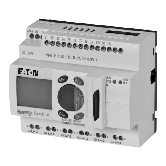
10/10 MN05003003Z-EN 1 Device application The controllers of the EC4-200 series are programmable switching EC4-200 part number overview and control devices. They can be used in domestic applications, The EC4-200 series contains controllers with different displays and machine building and plant construction. An EC4-200 controller the type and number of inputs/outputs. - Page 14 10/10 MN05003003Z-EN...
-
Page 15: Inputs
10/10 MN05003003Z-EN 2 Setup Inputs Table 1: Type and number of inputs Digital 12 (I1…I12) 24 V DC of which can be used 4 (I7, I8, I11, I12) 24 V DC/0…10 V as analog CAN/ STOP Inputs I7, I8, I11, I12 can also be used as analog inputs. They are selected in the user program by means of the appropriate syntax used in the PLC configurator. -
Page 16: Function And Cursor Buttons As Inputs
10/10 MN05003003Z-EN Setup Example: If you are using input I1 for a high-speed counter (16- Diagnostics inputs bit), I2 can be used for another high-speed counter (16-bit) but not The inputs I13, I14, I15, I16 provide you with additional for generating an interrupt. Inputs I3 and I4 likewise cannot be information: used for generating an interrupt. -
Page 17: Outputs
10/10 MN05003003Z-EN Outputs Outputs RUN/STOP/SF and CAN/NET LEDs After power up, the CPU can switch to the following states, as Table 2: Type and number of outputs indicated by the LEDs: EC4P-221/222-MT… 8 (Q1…Q8) 24 V DC/0.5 A transistor outputs Table 3: LED status indicator EC4P-221/222-MR…... -
Page 18: Real-Time Clock
10/10 MN05003003Z-EN Setup Splitting the RS232/Ethernet interface Real-time clock Using a cable splitter XT-RJ45-ETH-RS232 you can communicate The PLC is provided with a real-time clock that can be accessed in simultaneously via the RS232 and the Ethernet interface. the user program via functions from the SysLibRTC library. The connection between the PLC and the cable splitter is The functions are described in the PDF file „SysLibRTC“. -
Page 19: Cable Connections
10/10 MN05003003Z-EN Interfaces In order to supply the components in the cable, the RTS signal Cable connections device must be set in the (terminal) device, section “easy800- The following overview shows the cable types that can be PC-CAB connection cable” on page 95. connected to the PLC and their functions. -
Page 20: Can/Easynet Interfaces
10/10 MN05003003Z-EN Setup CAN/easyNet interfaces The PLC is provided with a CAN/easyNET interface with two slots that are internally connected via terminals. Figure 8: CAN/easyNet interfaces CANopen The CAN interface is designed as a CANopen interface in compliance with the CIA specification DS301V4.0. The PLC can be operated both as an NMT master as well as a CAN device on CAN networks. -
Page 21: Inputs
10/10 MN05003003Z-EN 3 Expansion units You connect the expansion devices directly to the PLC via the Inputs easyLink interface. The following expansion devices can be used to increase the number of PLC inputs and outputs. Table 6: Number of inputs and symbolic operands Type overview of expansion devices Part no. - Page 22 10/10 MN05003003Z-EN...
-
Page 23: Mounting On Top-Hat Rail
10/10 MN05003003Z-EN 4 Mounting Install the PLC in a control cabinet, a service distribution board or Mounting on top-hat rail in an enclosure so that the power supply terminals and other Place the device diagonally on the upper lip of the top-hat rail. terminals are protected against direct contact during operation. - Page 24 10/10 MN05003003Z-EN Mounting Figure 13: Screw fixing the devices a Fixing brackets EASY200-EASY EASY202-RE EASY6…-RE/-TE EASY-LINK-DS EC4-200 Figure 14: Connecting the expansion unit/network module to the EC4-200...
-
Page 25: Connecting The Power Supply
10/10 MN05003003Z-EN 5 Installation Connecting the power supply Connecting digital inputs Use input terminals I3 to I4 to connect pushbutton actuators, switches or 1 or 12-wire proximity switches. Given the high L01 + residual current, do not use 2-wire proximity switches. L01 –... -
Page 26: Setpoint Potentiometers Connection
10/10 MN05003003Z-EN Installation Temperature sensor connection Ensure that the reference potential is galvanically connected. Connect the 0 V of the power supply unit for the setpoint potentiometer and various sensors shown in the examples with the 0 V of the power supply. +24 V H +24 V H Setpoint potentiometers connection... -
Page 27: Connecting A Pulse Transmitter/Incremental Encoder
10/10 MN05003003Z-EN Connecting a pulse transmitter/incremental encoder Connecting the incremental encoder Connecting a pulse transmitter/incremental encoder Inputs I1 to I4 are designed so that high-speed signals from pulse L01 + transmitters/incremental encoders can be counted. L01 – The following connection options are possible: L02 + •... -
Page 28: Connecting Outputs
10/10 MN05003003Z-EN Installation Connecting outputs The relay or transistor outputs are used to switch loads such as fluorescent tubes, filament bulbs, contactors, relays or motors. Check the technical thresholds and output data before installing such devices ( page 100, 101). Connect relay outputs EC4P-221/222-MR…, EASY6..-DC-RE 24 V H 8 A... -
Page 29: Connecting Transistor Outputs
10/10 MN05003003Z-EN Connecting outputs Connecting transistor outputs EC4P-221/222-MT…, EASY6…-DC-TE F 10 A F 10 A EC4P-221/222-MT… 24 V f 2.5 A EASY6…-DC-TE 24 V 24 V H 0 V H f 2.5 A EC4P-221/222-MT… EASY6…-DC-… + 24 V H 24 V H 0.5 A 0.5 A 24 V H... -
Page 30: Connecting The Analog Output
10/10 MN05003003Z-EN Installation Connecting the analog output The EC4-200 is provided with one analog output QA 01, 0 V up to 10 V DC, 10-bit resolution (0 to 1023). The analog output can be used for controlling servo valves and other actuators. Connecting servo valve L01 + L01 –... -
Page 31: Memory Card, Can/Easynet, Pc Connection
10/10 MN05003003Z-EN Memory card, CAN/easyNet, PC connection Memory card, CAN/easyNet, PC connection To fit a memory card or establish a CAN/easyNet or PC connection, the protective cap must be removed first of all. Figure 31: Fitting/removing the memory card CAN/easyNet, PC connection Fit the plug for the CAN/easyNet connection into the opening at the top of the device a. -
Page 32: Connecting Expansion Devices/Network Modules
10/10 MN05003003Z-EN Installation Connecting expansion devices/network modules Local expansion Basic unit and expansion unit can be provided with Connect the devices to the expansion or to the network module different DC power supplies. via the EASY-LINK-DS connection plug. Remote expansion Remote expansion units can be installed and run up to 30 m away EASY-LINK-DS from the basic unit. -
Page 33: Keypad
10/10 MN05003003Z-EN 6 Operation The following chapter describes the operation of the buttons and Selecting or toggling between menu items the display on the front plate. Cursor Í Ú PROGRAM... STOP SET CLOCK...… Keypad INFORMATION... DEL: Delete Select or toggle ALT: Special function, status display ú... -
Page 34: Choosing The Main And System Menu
10/10 MN05003003Z-EN Operation Choosing the main and system menu Status display I 12..NT1SP BP MC DC MO 02:00 Q ..34…. STOP Local expansion password R ..34..RS SP BP MC DC MO 02:00 S..56.. STOP R = Inputs.. RS = Expansion S = Outputs.. -
Page 35: Menu Structure
10/10 MN05003003Z-EN Menu structure Menu structure Main menu without password protection You access the main menu by pressing OK. * Only use in STOP Main menu REPLACE ? MEMORY->FLASH BOOT PROJECT PROGRAMM…*) BOOT PROJECT å FLASH->CARD STOP RESET… CARD->FLASH STORED SET CLOCK…... -
Page 36: Main Menu With Password Protection
10/10 MN05003003Z-EN Operation Main menu with password protection Incorrect entry Main menu Password entry PASSWORD… Password STOP RUN å SET CLOCK… INFORMATION Correct entry Status display PASSWORD… System menu The System menu is accessed by simultaneously pressing DEL and ALT. Password setup System menu Password entry... -
Page 37: System Menu
10/10 MN05003003Z-EN Menu structure System menu PLC: STOP! System menu SYSTEM… NET...… NET PARAMETER... NET-ID :01 STARTPARAMETER LINK...… STATIONS… BAUDRATE:125KB MENU LANGUAGE CONFIGURE BUSDELAY: 00 å CONFIGURATOR SEND IO : REMOTE RUN ID of active devices Position within easyNet 0 = No device NET PARAMETER... - Page 38 10/10 MN05003003Z-EN...
-
Page 39: Password Protection
10/10 MN05003003Z-EN 7 Description of settings All settings are made using the operating elements on the Selecting the scope of the password controller. Press the OK button. PROGRAM å Select the function or the menu CLOCK to be protected. OPERATING MODE Password protection Press the OK button in order to protect the function or menu... -
Page 40: Access With Password Protection
10/10 MN05003003Z-EN Description of settings Access with password protection Changing or deleting the password range Password protection is deactivated once the password is entered. Enter your password. You can reactivate password protection later via the Password Press DEL and ALT to call up the System menu. menu or by switching the power supply off and on again. -
Page 41: Changing The Menu Language
10/10 MN05003003Z-EN Changing the menu language Changing the menu language Setting date and time Two menu languages can be selected. These can be set via the The devices are provided with a real-time clock with date and time. System menu. Set the hour, minute, day, month and year during initial commissioning. -
Page 42: Setting Lcd Contrast And Backlight
10/10 MN05003003Z-EN Description of settings The contrast setting is valid until it is changed again. Setting LCD contrast and backlight The background illumination of the LCD display can be switched CONTRAST: Use the cursor buttons Í Ú off. The display contrast can be set to one of five stages. The LIGHTING å... -
Page 43: Representation Of The Inputs/Outputs In The Configuration
10/10 MN05003003Z-EN 8 Configuration of the inputs/outputs (I/O) Representation of the inputs/outputs in the configuration Changing the folder function The direct addresses of the inputs/outputs are assigned symbolic Transistor Outputs Relay Outputs names beforehand in the PLC configuration. The Transistor Outputs are displayed as the default PLC configuration. -
Page 44: Displaying The Inputs/Outputs Of The Expansion Devices
10/10 MN05003003Z-EN Configuration of the inputs/outputs (I/O) Displaying the inputs/outputs of the expansion devices Click the “+” sign in front of the folder “Extension”. Right-click the “No Extension” folder Select a device from the Replace element menu. Figure 36: Selecting counters Figure 38: Selecting the expansion device The submenu will appear: Click the plus sign in front of the new device folder in order to... -
Page 45: General
10/10 MN05003003Z-EN 9 Operation Startup behaviour with boot project on the memory card General When the controller is switched on, a boot project on the memory card has priority over a project stored in the system memory. Overview of memory sizes If both projects are different, the boot project of the memory card is copied to the system memory and then started. - Page 46 10/10 MN05003003Z-EN Operation Power on Boot project on MMC? Boot project in the system memory (Flash)? Boot project in the system memory (Flash)? Boot project on MMC = Boot projet in the main memory (Flash)? Load boot project from the MMC into the working Load boot project from system memory memory Load boot project from the system memory...
-
Page 47: Setting The Startup Behaviour In The Programming Software
10/10 MN05003003Z-EN Setting the startup behaviour in the programming software Setting the startup behaviour in the programming Program START/STOP software With the setting of the start-up behaviour you determine the start Program start (STOP RUN) behaviour of the PLC when the supply voltage is switched on. You can start the program in two ways: The setting can be made in the PLC configurator or via the operating elements of the controller. -
Page 48: Starting/Stopping The Program Via External Switch
10/10 MN05003003Z-EN Operation Starting/stopping the program via external switch Reset An external switch connected to an input can be used to start or You can carry out a reset via the PC in online mode or via the stop the processing of the program. Some additional program controller menu. -
Page 49: Test And Commissioning
10/10 MN05003003Z-EN Test and commissioning Behaviour of variables after Reset Single-cycle mode In single-cycle operation, one program cycle is performed in real Variable type time. The outputs are enabled during the cycle. The cycle-time Reset Non-retentive Retain monitoring is active. Warm reset Activation of initial values Values remain in... -
Page 50: Counter Functions (Inputs/Outputs)
10/10 MN05003003Z-EN Operation It must be taken into account that the operations, such as Reset – A 1 signal at the Enable input activates the counter: The are processed via the program image. The output “Reset incoming pulses are counted. With the next 0 1 edge of the AT%QX1.2”... -
Page 51: Incremental Input
10/10 MN05003003Z-EN Incremental input 16-bit counter The function is available twice. The function of this counter is the same as that of the high-speed counter (32-bit). In order to identify the two 16-bit counters, the symbolic operands have a number: 0 or 1. -
Page 52: Overview Of Input/Output Signals (I/Q)
10/10 MN05003003Z-EN Operation Overview of input/output signals (I/Q) Referencing In many positioning controllers, a reference point is approached at the start of positioning. For example, a tool slide is moved to its Program symbolic Incremental home position. In this position, a reference switch is closed, thus addresses Input encoder... -
Page 53: System Events
10/10 MN05003003Z-EN System events System events System events are: START START: User program start (cold and warm start) COLDSTART Cold start of the user program WARMSTART Warm start of the user program STOP User program stop (does not apply to cycle time timeout or hardware watchdogs) I/O Interrupt Voltage change at inputs I1, I2, I3, I4... -
Page 54: Counter Interrupt
10/10 MN05003003Z-EN Operation Interrupt inputs I1 … I4 Timer interrupt Inputs I1 to I4 can be configured as interrupt inputs. An edge at You can create a program routine that is called at a fixed time the input generates an interrupt signal ( page 52) that calls the interval. - Page 55 10/10 MN05003003Z-EN System events Example • Create a program with a function call Create a program with the function TIMERINTERRUPTENABLE as per figure 51. • Creating the program routine Open the Task Configuration sub-directory with a double click in the Resources directory. Click here the System Events folder.
-
Page 56: Interrupt Processing
10/10 MN05003003Z-EN Operation Steps for interrupt processing Interrupt processing Define the interrupt properties: If an interrupt occurs, the program is interrupted and the program routine associated with the system event is processed. figure 54 Startup behaviour Select type shows a list of interrupt sources. TIMER INTERRUPT Call function TIMERINTERRUPTENABLE... -
Page 57: Direct I/O Access
10/10 MN05003003Z-EN Direct I/O access Figure 56: Interrupt edge selection Change over to the Task configuration and open the System Events folder. Figure 58: Allocation of Interrupt source l POU Select the “Fastprog” POU and confirm with OK. Save the project. You can now test it. The variable “b”... -
Page 58: Error Code For "Direct I/O Access
10/10 MN05003003Z-EN Operation Error code for “direct I/O access” Verify all functions as far as possible for the validity of the call parameters. If a fault is determined, access is not undertaken and an error code is output. The following return values are possible: Figure 59: ReadBitDirect function Function call: ReadBitDirect(uiSlot, uiBit, ptr_xValue) The following tables show the access options available:... -
Page 59: Generating And Transferring A Boot Project
10/10 MN05003003Z-EN Generating and transferring a boot project Storing a boot project on a memory card Generating and transferring a boot project The boot project stored in the system memory (Flash) can also be The CPU processes the user program stored in the main memory. stored on the memory card. -
Page 60: Download/Update Operating System
Download/update operating system The EC4-200 enables you to replace the currently stored operating system (OS) with a more recent version. The latest OS version can be downloaded from the Eaton website: http://www.eaton.com/moeller a Support It is also included on the latest easySoft-CoDeSys CD. -
Page 61: Transferring The Os From Pc To The Memory Card
10/10 MN05003003Z-EN Download/update operating system Figure 67: OS successfully transferred to the PLC In this window click the Exit button. Transferring the OS from PC to the memory card Loading an OS onto the memory card will delete the existing OS and the boot project on the memory card as well as the user program in the controller. - Page 62 10/10 MN05003003Z-EN...
-
Page 63: 10 Browser Commands
10/10 MN05003003Z-EN 10 Browser commands The PLC browser is a text based control monitor. This is where you Table 13: Browser commands enter commands in the entry line for scanning PLC status from the Get a list of implemented commends. PLC. -
Page 64: Description Of Important Browser Commands
10/10 MN05003003Z-EN Browser commands Description of important Browser commands canload setrtc Indicates the capacity utilisation of the CANopen fieldbus. Sets or changes the date and/or the time in the controller. Example: Syntax: <setrtc_YY:MM:DD:DW_HH:MM:SS> Legend: Space The last two digits of the year (00 F YY F 99) Month (01 F YY F 12) Day (01 F DD F 31) Figure 68: Browser command canload... -
Page 65: 11 Libraries, Function Blocks And Functions
10/10 MN05003003Z-EN 11 Libraries, function blocks and functions The libraries contain IEC function blocks and functions that you Installing additional system libraries can use, for example, for the following tasks: You can install libraries manually as follows: • Data exchange through the CANopen bus •... -
Page 66: Ec4-200 Specific Functions
10/10 MN05003003Z-EN Libraries, function blocks and functions EC4-200 specific functions EC_Util.lib library EC_Visu.lib/EC_Visu2.lib library This library contains the functions shown in the illustration below: The EC_Visu2.lib library contains function blocks for controlling the LCD display. Figure 72: EC_Visu2.lib library Figure 70: Functions of the EC_Util.lib library. The already available functions/function blocks SetBacklight, SetContrast and GetDisplayInfo from library CAN_BUSLOAD function... -
Page 67: Connection Setup Pc - Ec4-200
10/10 MN05003003Z-EN 12 Connection setup PC – EC4-200 The communication parameters of both the PC and the PLC must Defining/changing the PC’s communication settings match in order to establish a connection between them. The You can use the COM1 to COMx interfaces of the PC. default parameters are set as shown in figure 73 on devices that In the programming software define the communication are used for the first time. -
Page 68: Changing The Communication Parameters (Baud Rate) Of The Cpu
10/10 MN05003003Z-EN Connection setup PC – EC4-200 Changing the communication parameters (baud rate) of Connection setup via Ethernet the CPU After you have connected the PC to the PLC with an Ethernet Open the PLC configuration. cable, select the TCP/IP communication channel in the Click the Communication tab. - Page 69 10/10 MN05003003Z-EN Connection setup via Ethernet Compile the program and log out. Data transfer with TCP/IP (Level2Route) protocol This data transfer is supported by PLC types XC200, MFD4 and EC4-200 (only EC4P-222…). The data between the PC and PLC are transferred in data blocks of 128 Kbytes (default setting of the device).
-
Page 70: Scan/Modify The Ip Address
10/10 MN05003003Z-EN Connection setup PC – EC4-200 You are presented with a window indicating a drive and a flashing Scan/Modify the IP address cursor behind the drive designator. The “setipconfig” and “getipconfig” browser commands are For the example mentioned you would enter the following text: available for modifying and scanning the IP address section “ping 192.168.119.60”... -
Page 71: Overview
10/10 MN05003003Z-EN 13 Defining system parameters via the STARTUP.INI file Overview Creating the Startup.INI file You can create project-dependent system parameters and store When it is switched on for the first time (basic status), the them on the memory card. Here they are contained in the controller always works with the default system parameters, i.e. -
Page 72: Changing Settings
10/10 MN05003003Z-EN Defining system parameters via the STARTUP.INI file Changing settings The parameters are retained until you enter the browser command “removestartupini” and then switch the controller off and on again. The controller will now operate with the parameters of the project. -
Page 73: Prerequisites
10/10 MN05003003Z-EN 14 Programming:via a CANopen network (Routing) Routing means to establish an online connection from a Routing features of the controller programming device (PC) to any (routing-capable) PLC in a CAN The controller supports routing via the CAN bus. network without having to directly connect the programming device to the target PLC. -
Page 74: Notes On Routing
10/10 MN05003003Z-EN Programming:via a CANopen network (Routing) • The routing is independent of the configuration (master/slave): You can change this setting only if you have administrator a target PLC that has not been configured as a master or as a rights on your PC. -
Page 75: Setting The Master Station
10/10 MN05003003Z-EN Setting the master station Setting the master station Setting the device station Define two node IDs in the master station: Define two node IDs in the device (target) station: • One ID for routing • One ID for the routing function: The routing ID and the CAN •... -
Page 76: Plc Combinations For Routing
10/10 MN05003003Z-EN Programming:via a CANopen network (Routing) Enter the target ID of the target station, number 54 in the Example: Accessing a PLC program The example below illustrates the procedure for accessing a PLC example. The target ID is identical to the routing ID! program. - Page 77 10/10 MN05003003Z-EN 15 RS232 interface in Transparent mode In Transparent mode, data is exchanged between the EC4-200 and data terminal devices (e.g. terminals, printers, PCs, measuring devices) without any interpretation of the data. For this the serial interface RS232 (COM1/COM2 = Multifunction interface) must be switched to Transparent mode via the user program.
- Page 78 10/10 MN05003003Z-EN...
-
Page 79: Display Form
10/10 MN05003003Z-EN 16 Interactive display The use of functions and function blocks (FBs) enables you to Switching between Status display and Entry/output mode display variables (text/values) on the PLC display and enter values In the initial state, the display shows the status of the PLC. via the buttons/rocker switch. -
Page 80: Function/Function Block Overview
10/10 MN05003003Z-EN Interactive display Function block “Disp_DisplayPage” Function/function block overview For each variable you define its use, i.e. text display or value entry. The display in the Entry/output mode can be defined and The inputs of the function block must be parameterised for this controlled with the following functions/function blocks contained purpose. -
Page 81: Description Of Important Functions / Function Blocks
10/10 MN05003003Z-EN Description of important functions / function blocks Description of important functions / function blocks FUNCTION Disp_EnableDisplay: BOOL (*Changing Status display <-> Entry/output mode*) VAR_INPUT xEnable: (* FALSE: Status display, TRUE: Entry/output mode *) xDisableESCKey: (*Enabling of ESC button on local display and MFD-CP4: FALSE: Enable TRUE: Button disabled *) END_VAR... - Page 82 10/10 MN05003003Z-EN Interactive display FUNCTION_BLOCK Disp_GetDisplayInfo (* Actual information of the display status *) VAR_OUTPUT byMenueLevel :(* Menu level: (*0: Status menu (*1: Main menu (*2: Main menu / program (*3: Main menu / Set clock (*4: Main menu / information (*5: System menu (*6:...
- Page 83 10/10 MN05003003Z-EN Description of important functions / function blocks TYPE DISP_ATTRIBUT : ( DISP_ATTR_NORMAL := 0, DISP_ATTR_REVERSE, DISP_ATTR_BLINK ) := DISP_ATTR_NORMAL; END_TYPE FUNCTION_BLOCK Disp_DisplayPage (* Display of a screen *) VAR_INPUT xEnable: (* TRUE: Activate display *) xEnableInput: (* TRUE: Activate Entry *) byNoOfElements: (* Number of elements for this screen 1 - 12*) aElementDescription:ARRAY [1..12]...
-
Page 84: General Programming Procedure
10/10 MN05003003Z-EN Interactive display Relationship between DISP_DisplayPage.xEnable/ General programming procedure xEnableInput and DISP_ElementDescription.xInputEnable • Declaration of the (display) variables to display for the value entry entry in the list “Global_Variables_Display” figure 95 • Program creation 3 programs (for each example) are created: –... -
Page 85: Example Of Text And Values Output
10/10 MN05003003Z-EN Description of important functions / function blocks Example of text and values output (with the Disp_DisplayElement FB) The display is required to display the values of the variables “motor1” and “motor2”. The two values are changed continuously by the user program. Figure 95: Declaration of display variables Figure 94: Example of text and values output Creating auxiliary variables... - Page 86 10/10 MN05003003Z-EN Interactive display Creating the program “Visualisation” Disp_RegisterVariable('S2', ADR(g_sDisp_String2), Depending on the status of auxiliary variable DISP_TYP_STRING); “g_xFirstCycleAfterStartProgram” register the variables for which Disp_RegisterVariable('V1', ADR(PLC_PRG.byValue), the text/value is to be displayed: DISP_TYP_BYTE); Disp_RegisterVariable('V2', ADR(PLC_PRG.wValue), Program the function “Disp_RegisterVariable” with the DISP_TYP_WORD);...
-
Page 87: Example Of A Screen Output With Texts And Value Entries
10/10 MN05003003Z-EN Description of important functions / function blocks Example of a screen output with texts and value entries Declaring display variables First declare for each text element that you wish to display, such With the Disp_DisplayPage function block as “MO11”, a variable of type “String” in the The following display has to be implemented. - Page 88 10/10 MN05003003Z-EN Interactive display PROGRAM Visualization (***************) xIsDisplayEnabled :BOOL; fbDisplayPage1 :Disp_DisplayPage; byError :BYTE; siValue :SINT; END_VAR ------------------------------------------------------------ (* Initialisation in the first cycle after program start *) IF g_xFirstCycleAfterStartProgram = TRUE THEN Disp_RegisterVariable('S1', ADR(g_sDisp_String1), DISP_TYP_STRING); Disp_RegisterVariable('S2', ADR(g_sDisp_String2), DISP_TYP_STRING); Disp_RegisterVariable('S3', ADR(g_sDisp_String3), DISP_TYP_STRING); Disp_RegisterVariable('S4', ADR(g_sDisp_String4), DISP_TYP_STRING);...
- Page 89 10/10 MN05003003Z-EN Description of important functions / function blocks fbDisplayPage1.aElementDescription[7].byLine := 3; fbDisplayPage1.aElementDescription[7].byColumn := 8; fbDisplayPage1.aElementDescription[7].byDigits := 9; fbDisplayPage1.aElementDescription[7].byPrecision := 0; fbDisplayPage1.aElementDescription[7].xInputEnable := TRUE; fbDisplayPage1.aElementDescription[7].diMinInputValue := 0; fbDisplayPage1.aElementDescription[7].diMaxInputValue := 4444444; fbDisplayPage1.aElementDescription[8].sName := 'V4'; fbDisplayPage1.aElementDescription[8].byLine := 4; fbDisplayPage1.aElementDescription[8].byColumn :=13; fbDisplayPage1.aElementDescription[8].byDigits := 4; fbDisplayPage1.aElementDescription[8].byPrecision := 0;...
-
Page 90: Multifunction Display Mfd-Cp4 On The Ec4-200
10/10 MN05003003Z-EN Interactive display Multifunction display MFD-CP4 on the EC4-200 Local Mode TERMINAL The multi-function display (MFD-CP4) enables you to implement Main menu externally the same display and operating functions available on COM… same display as the the PLC. MENU LANGUAGE… controller's display LIGHTING: 80% CONTRAST:... -
Page 91: Easy205-Asi
10/10 MN05003003Z-EN 17 EC4-200 network modules The EASY205-ASI, EASY221-CO, EASY204-DP, EASY222-DN EASY205-ASI network interfaces enable you to connect the EC4-200 as a slave to ASI, CAN, PROFIBUS-DP or DeviceNet ( table 18) networks. The controller can also be integrated as a station in an easyNet Cyclic data exchange network. -
Page 92: Configuration
10/10 MN05003003Z-EN EC4-200 network modules Configuration Master The configuration is carried out in the PLC configuration of the PROFIBUS-DP/ easy Soft CoDeSys programming software. The network module is CANopen/DeviceNet entered as an expansion device in the configuration tree. This contains predefined input and output channels (R1…R8, S1…S4) for the cyclical transfer of data. -
Page 93: Configuration
10/10 MN05003003Z-EN EASY221-CO, EASY204-DP, EASY222-DN The objects listed in the table are supported by the EC4-200 and Configuration can be addressed by a master on the CAN, PROFIBUS-DP or The configuration is carried out in the PLC configuration of the DeviceNet. - Page 94 10/10 MN05003003Z-EN EC4-200 network modules Start addreses for inputs/outputs and markers The start addresses for the address ranges of the inputs and outputs can be set in the PLC configuration. The marker range is shown in table 22. Figure 107: Setting the address ranges The configuration and setting of the station address was already described in the section “Cyclical data exchange”.
- Page 95 10/10 MN05003003Z-EN EASY221-CO, EASY204-DP, EASY222-DN Word 54 (106) 53 (104) 52 (102) 51 (100) 50 (98) 49 (96) DWord 27 (104) 26 (100) 25 (96) Word 60 (118) 59 (116) 58 (114) 57 (112) 56 (110) 55 (108) DWord 30 (116) 29 (112) 28 (108) Word...
- Page 96 10/10 MN05003003Z-EN...
-
Page 97: Network Can/Easynet
10/10 MN05003003Z-EN Network CAN/easyNet Appendix Calculating the cable length for a known cable resistance Network CAN/easyNet If the resistance of the cable per unit of length is known (resistance per unit length R’ in O/m), the entire cable resistance R must not exceed the following values. -
Page 98: Switch
10/10 MN05003003Z-EN Appendix Example program for PLC START/STOP using external switch The SysLibPlcCtrl.lib library contains the function SysStartPlcProgram required for the start, and the function SysStopPlcProgram required for the stop. In this case, the startup behaviour of the controller must be set to WARM START in the PLC Configurator under <Other Parameters Settings>! Figure 110: Declaring global variables... -
Page 99: Easy800-Pc-Cab Connection Cable
10/10 MN05003003Z-EN easy800-PC-CAB connection cable Dimensions and weight 9-pole socket connector on the cable (Terminal/PC plug) Signal Dimensions W x H x D [mm] 107.5 x 90 x 72 with adapter for MMC 107.5 x 90 x 79 [inches] 4.23 x 3.54 x 2.84 with adapter for MMC 4.23 x 3.54 x 3.11 Space units (SU) width... -
Page 100: Technical Data
10/10 MN05003003Z-EN Appendix Technical data Climatic environmental conditions (Cold to IEC 60068-2-1, Heat to IEC 60068-2-2) Operational ambient temperature °C, (°F) –25 to 55, (–13 to 131) Installed horizontally/vertically Condensation Prevent condensation with suitable measures LCD display (reliably legible) °C, (°F) 0 to 55, (–32 to 131) Storage/transport temperature °C, (°F) - Page 101 10/10 MN05003003Z-EN Slot-head screwdriver, width 3.5 x 0.8 inch 0.14 x 0.03 Tightening torque Memory specifications Program code kByte Program data kByte 14 segments of 16 KB each Marker/Input/Output/Retain data kByte 16/4/4/8 Cycle time for 1 k instructions < 0.3 Back-up/Accuracy of the real-time clock Back-up of the clock 25°C...
- Page 102 10/10 MN05003003Z-EN Appendix CAN(open)/easyNet Transfer rate kBit/s 10, 20, 50, 100, 125, 250, 500 Default: 125 Potential isolation from inputs/outputs/power supply Bus termination resistor 120 O or EASY-NT-R plug (incl. bus terminating resistor 120 O) Terminals 2 x RJ45, 8pole CAN(open) operating mode: –...
- Page 103 10/10 MN05003003Z-EN Technical data Delay time from 0 to 1 I1 to I4 0.02 I5 to I12 0.25 Delay time from 1 to 0 I1 to I4 0.02 I5 to I12 0.25 Cable length (unshielded) Additional input functions Inputs for analog signals Number 4 (I7, I8, I11, I12) Signal range...
- Page 104 10/10 MN05003003Z-EN Appendix Relay outputs Number of outputs Parallel switching of outputs to increase performance Not permissible Protection of an output relay Miniature circuit-breaker B16 or fuse (slow-blow) Electrical isolation Safe isolation V AC Basic insulation V AC Mechanical lifespan Switch 10 x 106 operations...
-
Page 105: Transistor Outputs
10/10 MN05003003Z-EN Technical data Relay switching frequency Mechanical switch operations Switch 10 mill. (107) operations Mechanical switching frequency Resistive lamp load Inductive load Transistor outputs Number of outputs Rated voltage U V DC Permissible range V DC 20.4 bis 28.8 Residual ripple Supply current On 0 state, typical/maximum... - Page 106 10/10 MN05003003Z-EN Parallel connection of outputs with resistive load; inductive load with external suppression circuit (a section “Connecting transistor outputs”, page 25); combination within a group Group 1: Q1 to Q4 Group 2: Q5 - Q8 Maximum number of outputs total maximum current h Caution! Outputs connected in parallel must be switched at the...
-
Page 107: Analog Output
10/10 MN05003003Z-EN Analog output Quantity Potential isolation to power supply From the digital inputs To the digital outputs from the easy-NET network Output type DC voltage Signal range V DC 0 bis 10 Output current max. Load resistor Short-circuit and overload proof Resolution, analog 0.01 Resolution, digital... -
Page 108: Character Sets
10/10 MN05003003Z-EN Appendix Character sets Latin 1, Western European Code Meaning Code Meaning Code Meaning Code Meaning Space € À ‰ Á ´ Â Ã „ Ä Å Æ Ç È É Ê Ë Ì Í Î Ï Ä Ð Å... - Page 109 10/10 MN05003003Z-EN Character sets Character set Latin 2, “Central European” (for Polish, Hungarian and Czech) Code Meaning Code Meaning Code Meaning Code Meaning Space € Ŕ ¢ Á ´ Â Ă „ Ä Ĺ Ć Ç Č ‰ É Š Ę...
- Page 110 10/10 MN05003003Z-EN Appendix Character set “Cyrillic” (for Russian) Code Meaning Code Meaning Code Meaning Code Meaning Space € ѓ Б ´ ѓ Г „ Д ² Ƌ ³ ƌ И ‰ Й Љ К < Л Њ Ќ Ћ ƾ П...
- Page 111 10/10 MN05003003Z-EN Index Connecting Adapter Memory card ......27 20 mA sensor ......22 Addressing, PLC on CANopen fieldbus .
- Page 112 10/10 MN05003003Z-EN Index easyNET Inputs Interface ....... .27 Symbolic operands ......17 Engineering .
- Page 113 10/10 MN05003003Z-EN Index Setpoint potentiometers Operating system update ..... . . 41 Connecting ......22 Operating system, download/update .
Need help?
Do you have a question about the easyControl EC4-200 and is the answer not in the manual?
Questions and answers