
Subscribe to Our Youtube Channel
Related Manuals for Advantech SOM-9590


Summary of Contents for Advantech SOM-9590
- Page 1 User Manual SOM-9590 Intel® Xeon® Processor D-1500 COM Express R3.0 Type 7 Module for Harsh Environments...
- Page 2 No part of this manual may be reproduced, copied, translated or transmitted in any form or by any means without the prior written permission of Advantech Co., Ltd. Information provided in this manual is intended to be accurate and reliable. How- ever, Advantech Co., Ltd.
- Page 3 Class I, Division 2, Groups A, B, C, and D indoor hazards. Technical Support and Assistance Visit the Advantech website at http://support.advantech.com where you can find the latest information about the product. Contact your distributor, sales representative, or Advantech's customer service center for technical support if you need additional assistance.
- Page 4 Before setting up the system, check that the items listed below are included and in good condition. If any item does not match the description on the table, please con- tact your dealer immediately. SOM-9590 CPU module Heat spreader ...
- Page 5 The sound pressure level at the operator's position according to IEC 704-1:1982 is no more than 70 dB (A). DISCLAIMER: This set of instructions is given according to IEC 704-1. Advantech disclaims all responsibility for the accuracy of any statements contained herein.
- Page 6 Serial Presence Detect – refers to serial EEPROM on DRAMs that has DRAM Module configuration information Trusted Platform Module – chip to enhance the security features of a com- puter system UEFI Unified Extensible Firmware Interface Watchdog Timer SOM-9590 User Manual...
-
Page 7: Table Of Contents
Figure 3.23 CPU HWPM State Control........43 Figure 3.24 CPU Advanced PM Turning ........44 Figure 3.25 DRAM RAPL Configuration ........45 Figure 3.26 SOCKET RAPL Configuration ......... 46 Figure 3.27 Common RefCode Configuration ......47 Figure 3.28 Memory Configuration -1 ......... 48 SOM-9590 User Manual... - Page 8 S/W Introduction & Installation..87 S/W Introduction ..................88 Driver Installation ..................88 4.2.1 Windows Driver Setup ..............88 4.2.2 Other OS..................88 Advantech iManager ................89 Appendix A Assignment......... 91 SOM-9590 Type 7 Pin Assignment............92 SOM-9590 User Manual viii...
-
Page 9: Chapter 1 General Information
Chapter General Information This chapter details background information on the SOM-9590 CPU Computer on Module Sections include: Introduction Functional Block Diagram Product Specification... -
Page 10: Introduction
PCIe storage device management if the CPU fails, and is conve- nient for applications requiring continuous service. SOM-9590 has four screw holes near the CPU, positioned in compliance with the Intel® stan- dard thermal design guide. The thermal module is attached to the CPU in a balanced torque design, and is the first COM Express to have an added backplane to increase rigidity. -
Page 11: Functional Block Diagram
1 PCIe x1 Gen2 GPIO 16GB 4 USB 3.0 SATA 2 10GBast-KR Xeon D-1539 (8C,35W) I2C/ WDT 2 UART XDP Conn. (TX/RX) Embedded GPIO (option) Controller IT 8528 Thermal Ctl. Fan Ctl. PWR Mgt. BIOS TPM 2.0 SOM-9590 User Manual... -
Page 12: Product Specification
Power Button Support 1 / 1 Power Good 1 / 1 VCC_5V_SBY Contacts 4 / 4 Sleep Input 0 / 1 Lid Input 0 / 1 Carrier Board Fan Control 0 / 1 Power R3.0 Type 7 SOM-9590 SOM-9590 User Manual... - Page 13 Intel® Xeon® Processor D Family is does not support graphics processing. SOM- 9590 does not support display or audio functionality. Graphics will be defined accord- ing to specific user scenarios based on system specification. Please contact Advant- ech sales or FAE for more details. SOM-9590 User Manual...
- Page 14 Intel Xeon® Processor D natively integrates one x16 PCI Express interface sup- porting up to 4 devices at Gen3 speeds (8 GHz). SOM-9590 supports one PCIe x16, and is configurable for 2 x8, 1 x8 and 2 x4, or 4 x4.
- Page 15 BIOS chip on the carrier board with an appropriate design and jumper setting on BIOS_DIS#[1:0]. BIOS_DIS0# BIOS_DIS#1 Boot up destination/function Open Open Boot from module’s SPI BIOS Open Boot from carrier board LPC/FWH BIOS Open SPI_CS0# to carrier board, SPI_CS1# to module SPI_CS0# to module, SPI_CS1# to carrier board SOM-9590 User Manual...
- Page 16 LPC Wake: depends on user inquiry and may need customized BIOS Advantech S5 ECO Mode (Deep Sleep Mode) Advantech iManager provides additional features to allow the system to enter a very low suspend power mode – S5 ECO mode. In this mode, the module will cut all power, including suspended and active power, to the chipset and keep an on-module controller active.
- Page 17 MIL-HDBK-217F N2: Please refer Advantech SOM-9590 Series Reliability Prediction Report No: CERT-19-01288.Link: http://com.advantech.com OS Support The mission of Advantech Embedded Software Services is to "Enhance quality of life with Advantech platforms and Microsoft Windows embedded technology." We enable Windows Embedded software products on Advantech platforms to more effectively support the embedded computing community.
- Page 18 The layout checklist will specify the layout con- straints and recommendations for trace length, impedance, and other design information. Please contact your nearest Advantech branch office for design documents and advanced support. Link: http://com.advantech.com SOM-9590 User Manual...
-
Page 19: Chapter 2 Mechanical Information
Chapter Mechanical Information This chapter details mechanical information on the SOM-9590 CPU Computer on Module. Sections include: Board Information Mechanical Diagram Assembly Diagram... -
Page 20: Board Information
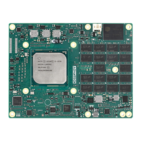
Board Information The figures below detail the main chips for SOM-9590 Computer-on-Module. Please be aware of their position while designing your carrier board and thermal solution contact points to avoid mechanical issues and improve thermal dissipation perfor- mance. Figure 2.1 Board Chips Location Diagram - Front Figure 2.2 Board Chips Location Diagram- Back... -
Page 21: Connector List
2.1.1 Connector List Table 2.1: FAN1 Fan FAN1 Description Wafer 2.0 mm (0.7 in) 3P 90D(M)DIP 2001-WR-03-LF W/Lock Pin Name Fan Tacho-Input Fan Out SOM-9590 User Manual... -
Page 22: Mechanical Diagram
Mechanical Diagram For more details about 2D/3D models, go to Advantech’s COM support service web- site Link: http://com.advantech.com Figure 2.3 Board Mechanical Diagram - Front Figure 2.4 Board Mechanical Diagram - Back SOM-9590 User Manual... - Page 23 2.07 Figure 2.5 Board Mechanical Diagram - Side SOM-9590 User Manual...
-
Page 24: Assembly Diagram
Assembly Diagram These figures demonstrate the thermal module assembly procedure, for the COM module and the carrier board. There are four reserved screw holes enabling SOM- 9590 to be pre-assembled with the heat spreader. SOM-9590 User Manual... -
Page 25: Chapter 3 Bios Setup Information
Chapter BIOS Setup Information Sections include: Introduction Entering Setup Hotkey Operation Exit BIOS Setup Utility... -
Page 26: Introduction
Introduction SOM-9590 BIOS is stored on a flash ROM inserted into a BIOS socket on the board. Users can modify BIOS settings and control various system features with the BIOS setup program. This chapter describes the basic navigation of the SOM-9590 BIOS setup screens. -
Page 27: Entering Setup
<Esc> key is used to Quit without saving. Enter Entering submenu or display option items. SOM-9590 BIOS has a built-in Setup program that allows users to modify basic sys- tem configuration. This information is stored in flash ROM so it retains setup informa- tion when the power is turned off. -
Page 28: Main Setup
No option sion. Displays the BIOS supporting industry stan- Compliancy No option dards compliance. Displays the project version of Advantech Project Version No option projects. Build Date and Time No option Displays BIOS set date and time. Please refer to manual section "3.1.4 Secu-... -
Page 29: Advanced Bios Features Setup
3.2.2 Advanced BIOS Features Setup Select the Advanced tab from the SOM-9590 setup screen to enter the Advanced BIOS Setup screen. Users can select any item in the left frame of the screen, such as CPU Configuration, and enter the sub menu for that item. Users can display an Advanced BIOS Setup option by highlighting it using the <Arrow>... - Page 30 TPM 1.2 will restrict support to TPM 1.2 devices. TPM1.2 TPM 2.0 will restrict support to TPM2.0. Auto will Device Select TPM2.0 support both with the default set to TPM2.0 Auto devices if not found, TPM 1.2 devices will be enu- merated. SOM-9590 User Manual...
- Page 31 Enable or disable system’s ability to Disable hibernate (operating system S4 sleep Enable Hibernation Enable state). Needs OS support for this fea- ture. Disable Lock Legacy Resource Enables or disables legacy resource. Enable SOM-9590 User Manual...
- Page 32 Native or Invert according Invert to LVDS panel. Normal Select Power Saving mode to Power Saving Mode Deep Sleep Normal or Deep Sleep. I210 GbE Select PCIe switch as GbE PCIe Switch setting Carrier PCIe Port7 LAN or PCIe. SOM-9590 User Manual...
- Page 33 Figure 3.7 Serial Port 1 Configuration Feature Option Description Disable Serial Port Enable or Disable Serial Port (COM) Enable Device Settings No option The current settings Auto I/O=3E8h; IRQ=4; I/O=3F8h; IRQ=3,4,5,6,7,9; Change Settings Serial port address I/O=2F8h; IRQ=3,4,5,6,7,9; I/O=3E8h; IRQ=3,4,5,6,7,9; I/O=2E8h; IRQ=3,4,5,6,7,9; SOM-9590 User Manual...
- Page 34 Figure 3.8 Serial Port 2 Configuration Feature Option Description Disable Serial Port Enable or Disable Serial Port (COM) Enable Device Settings No option The current settings Auto I/O=2E8h;IRQ=3; I/O=3F8h;IRQ=3,4,5,6,7,9; Change Settings Serial port address I/O=2F8h;IRQ=3,4,5,6,7,9; I/O=3E8h;IRQ=3,4,5,6,7,9; I/O=2E8h;IRQ=3,4,5,6,7,9; SOM-9590 User Manual...
- Page 35 COM Module FAN No option Shows the current status. Carrier Board FAN No option Shows the current status. +VBAT No option Shows the current status. +V5SB No option Shows the current status. +VIN No option Shows the current status. SOM-9590 User Manual...
- Page 36 Console Redirection Settings <Sub Menu> Legacy Console <Sub Menu> Legacy Console Redirection Settings Redirection Settings Serial Port for Out-of- and Management / Win- Disable Console Redirection Enable or Disable dows Emergency Enable Console Redirection Settings <Sub Menu> Management Services (EMS) SOM-9590 User Manual...
- Page 37 To allow a PCI device to Disable generate an SERR PERR# Generation Enable number for a PCI Bus- Signal Error Event. SOM-9590 User Manual...
- Page 38 Disable To choice PCIe port 1 PCH PCIe Port Config 1 Enable configuration. Disable To choice PCIe port 2 PCH PCIe Port Config 2 Enable configuration. SOM-9590 User Manual...
- Page 39 3.2.2.5 Network Stack Configuration Figure 3.12 Network Stack Configuration Feature Options Description Disable Network Stack Enable or Disable Network Stack. Enable SOM-9590 User Manual...
- Page 40 Controls the execution of UEFI and Network Legacy legacy PXE OpROM UEFI Do not launch Controls the execution of UEFI and Storage Legacy legacy storage OpROM UEFI Do not launch Controls the execution of UEFI and Video Legacy legacy video OpROM UEFI SOM-9590 User Manual...
- Page 41 Other PCI devices Legacy for devices other than network, stor- UEFI age, or video 3.2.2.7 NVMe Configuration Figure 3.14 NVMe Configuration Feature Options Description User can start the setting after NVMe Device Options Setting No option inserting NVMe device. SOM-9590 User Manual...
- Page 42 USB keyboard legacy support for non-USB aware OS. Enabled This time-out value for Control, Bulk, and USB transfer time-out Disabled Interrupt transfers. Enabled USB mass storage device start unit com- Device reset time-out Disabled mand time-out. SOM-9590 User Manual...
-
Page 43: Intelrcsetup
3.2.3 IntelRCSetup Select the IntelRCSetup tab from the SOM-9590 setup screen to enter the BIOS Setup screen. You can select the items by highlighting it using the <Arrow> keys. All Plug-and-Play BIOS Setup options are described in this section. The Plug-and-Play BIOS Setup screen is shown below. - Page 44 3.2.3.1 Processor Configuration Figure 3.17 Processor Configuration #1 Figure 3.18 Processor Configuration #2 SOM-9590 User Manual...
- Page 45 MSR 31h Bit [0] -A write of 1 selects 32KB 8Way Without ECC DCU Mode the DCU mode as 16KB 4-way with 16KB 4Way Without ECC ECC. Auto Direct Cache Access Enable Enables Direct Cache Access. (DCA) Disable SOM-9590 User Manual...
- Page 46 No option (Hex) G bitmask. QLRU Config [31:0] VIRTUAL_MSR_CR_QLRU_CONFI No option (Hex) G bitmask. Enable Enable or disable the SMM Save SMM Save State Disable State feature. Enable Enable or disable Targeted Smi Fea- Targeted Smi Disable ture. SOM-9590 User Manual...
- Page 47 Config TDP [28]. Option to disable/enable Config Disable TDP. Enable IOTG setting via sticky scratch pad IOTG Setting Disable register. Auto Override Uncore max CLR Freq ratio Uncore CLR Freq OVRD Manual programming to MSR 0x620 bits [6:0]. SOM-9590 User Manual...
- Page 48 Select the performance state that BIOS will set before mode Max Effi- OS hand-off. cient Turbo mode allows a CPU logical processor to exe- Enable Turbo Mode cute a higher frequency when enough power is avail- Disable able not exceeding CPU defined limits. SOM-9590 User Manual...
- Page 49 – XE Ratio Limit Figure 3.21 XE Ratio Limit Feature Options Description Enable Overclocking Lock Enable/disable Overclocking. Disable SOM-9590 User Manual...
- Page 50 OS. Recommended to be disabled. Enhances Halt Enable Enable or disable the Enhanced C1E state State (C1E) Disable of the CPU, takes effect after reboot. ACPI C2 Report CC3/CC6 to OS ACPI C2 or ACPI OS ACPI Cx ACPI C3 SOM-9590 User Manual...
- Page 51 Figure 3.23 CPU HWPM State Control Feature Options Description Enable Enable CPU HWPM for CPU Enable CPU HWPM Disable for better energy performance. Enable CPU Autonomous Enable Enable or disable CPU Auton- Cstate Disable omous C State. SOM-9590 User Manual...
- Page 52 Program PowerCTL MSR 0x1FC Sub Program PowerCTL_MSR No option Menu Program Program No option PRI_PLANE_CURT_CFG_CTRL_MSR PRO_CURT_CFG_CTRL_MSR 0x601 Sub Menu. Program CSR_ENTRY_CRITERIA Program CSR_ENTRY_CRITERIA No option 1:10:2:0x7C Sub Menu. Program CSR_SWL TROVRD Program CSR_SWL TROVRD No option 1:10:1:0x78 Sub Menu. SOM-9590 User Manual...
- Page 53 DRAM RAPL DRAM RAPL Baseline enabled and baseline DRAM RAPL Mode 0 Baseline mode. Disable Override Allows custom tuning of BW_LIMIT_TF when BW_LIMIT_TF DRAM RAPL is enabled. DRAM RAPL Enable Extended Select DRAM RAPL Extended Range Disable Range SOM-9590 User Manual...
- Page 54 Short Dur Pwr Short Duration Power Limit (aka Power Limit 2) value n Limit Watts. The value may vary from 0 to 32767. Pkg Clmp Bewtee P1/P0 Pkg Clamping limit 2, Allow going below P1. Lim2 Below P1 SOM-9590 User Manual...
- Page 55 MMIOH Base [63:32] ; must be MMIOBase between 4032 – 4078. 256G 128G 512G MMIO High 1024G Select MMIO High Size. Size 2048G 4096G 8192G Enable Isoc Mode IsocL Disable, Enable. Disable Enable NeSeg Mode MeSeg: Disable, Enable. Disable SOM-9590 User Manual...
- Page 56 Determines if MRV warnings are pro- mote Warn- Disable moted to system level1. ings Promote Enable Determines if warnings are promoted Warnings Disable to system level1. Halt on mem Enable Halt on mem Training Error Disable/ Training Error Disable Enable. SOM-9590 User Manual...
- Page 57 CH. Value 2 applies WA on CH1, 3 CH Mask on CH0 and 1. Auto Rank Margin Enables the rank margin tool to run Disable Tool after DDR4 memory training. Enable RMT Pattern Set the pattern length for the Rank 32767 Length Margin Tool. SOM-9590 User Manual...
- Page 58 Enable fast boot. Disable Auto Enable or disable Rank Margin Tool on RMT on Cold Fast Boot. Enable Cold Fast Boot. Disable Enable BDAT Enable or disable BDAT. Disable Auto Data Scrambling Enable Enable data scrambling. Disable SOM-9590 User Manual...
- Page 59 C/A Parity Enable Enable Address Parity. Disable Auto Sets DDR4 SMB Clock Frequency for SMB Clock Frequency 400 Khz SPD Access. 1 Mhz Enable Select ranks to enable or disable per DIMM Rank Enable Mask Disable DIMM. SOM-9590 User Manual...
- Page 60 Figure 3.30 Memory Topology Display memory topology with DIMM population information. SOM-9590 User Manual...
- Page 61 Enable shut down MDLL during SR Disable Disable Configure MEMHOT Input and Output MEMHOT Throttling Mode Input-only Mode: Mem Hot Sense Therm Throt or Output-only Mem Hot Output Therm Throt. Disable Configure Memory Electrical Throt- MEM Electrical Throttling Enable tling. Auto SOM-9590 User Manual...
- Page 62 Figure 3.32 Memory Power Saving Advanced Options Allows users to configure CK behaviors during self-refresh. Memory Timings & Voltage Override Figure 3.33 Memory Timing & Voltage Override SOM-9590 User Manual...
- Page 63 Splits the 0 ~ 4GB address space Socket Interleave Disable between two sockets, so that both Below 4GB Enable sockets get a chunk of local memory below 4GB. Auto 1-way Interleave Channel Interleav- 2-way Interleave Select Channel Interleaving setting. 3-way Interleave 4-way Interleave SOM-9590 User Manual...
- Page 64 Numbers Leaky Bucket low bit Numbers Leaky Bucket high bit Numbers Auto DRAM Maintenance Manual Disable Enable Patrol Scrub Disable Patrol Scrub Interval Numbers Enable Demand Scrub Disable Enable Device Tagging Disable Enable Memory Power Management Disable SOM-9590 User Manual...
- Page 65 Enable or disable DMI Vc1. Disable Enable DMI Vcp Control Enable or disable DMI Vcp. Disable Enable DMI Vcm Control Enable or disable DMI Vcm. Disable VC0 No-Snoop Configu- Enable Enable No-Snoop on reads and ration Disable writes for Vc0 traffic. SOM-9590 User Manual...
- Page 66 No PCIe port PCU Squelch eixt ignore option Workaround settings when no PCIe active ECO Reset the SQ FLOP by CSR option port active. IOU1 Non- Enable Posted Prefetch Disable SOM-9590 User Manual...
- Page 67 Figure 3.38 Socket 0 PcieD01F0 - Port 1A In auto mode, the BIOS will remove the EXP port if there is no device, errors on that device, or if the device is not HP capable. Use disable to hide its CFG space. SOM-9590 User Manual...
- Page 68 In auto mode, the BIOS will remove the EXP port if there is no device, errors on that device, or if the device is not HP capable. Use disable to hide its CFG space. – Socket 0 PcieD02F2 – Port 2C Figure 3.40 Socket 0 PcieD02F2 – Port 2C SOM-9590 User Manual...
- Page 69 In auto mode the BIOS will remove the EXP port if there is no device, errors on that device, or device is not HP capable. Disable is used to disable the port and hide its CFG space. SOM-9590 User Manual...
- Page 70 In auto mode the BIOS will remove the EXP port if there is no device, errors on that device, or if device is not HP capable. Disable is used to disable the port and hide its CFG space SOM-9590 User Manual...
- Page 71 In auto mode the BIOS will remove the EXP port if there is no device, errors on that device, or if device is not HP capable. Disable is used to disable the port and hide its CFG space. SOM-9590 User Manual...
- Page 72 In auto mode the BIOS will remove the EXP port if there is no device, errors on that device, or if device is not HP capable. Disable is used to disable the port and hide its CFG space SOM-9590 User Manual...
- Page 73 Figure 3.45 I/O AT Configuration Feature Options Description Enable Enable IOAT Control to enable or disable IIOAT devices. Disable Enable No Snoop No Snoop enable or disable for each CB device. Disable Enable Disable TPH TLP Processing Hint disable. Disable SOM-9590 User Manual...
- Page 74 3M DPR 1M DPR TXT DPR memory Allow selection of the TXT DPR size 64M DPR setting in system. 128M DPR 256M DPR IIO 0 No option Enable IIO IOAPIC Enable or disable the IIO IOAPIC. Disable SOM-9590 User Manual...
- Page 75 Enable or disable VT-F Interrupt Remapping Interrupt Remapping Disable support. Enable Enable or disable non-Isoch VT-D Engine Coherency Support (Non-Isoch) Disable Coherency support. Enable Enable or disable Isoch VT-D Engine Coher- Coherency Support (Isoch) Disable ency support. SOM-9590 User Manual...
- Page 76 Figure 3.48 I/O South Complex Configuration Feature Options Description Auto SC GbE PF0 (10GbE) Enable Force Enable or disable SC GbE physical function 0. Disable Auto SC GbE PF1 (10GbE) Enable Force Enable or disable SC GbE physical function 1. Disable SOM-9590 User Manual...
- Page 77 3.2.3.12 PCH Configuration Figure 3.49 PCH Configuration PCH Devices Figure 3.50 PCH Devices SOM-9590 User Manual...
- Page 78 Disable Enable Spread Spectrum – only affects Enable – CK420 Enable external clock generator. PCH state after G3 Select S0/S5 for ACPI state after a G3. Las State Disable PCH CRID Enable or disable PCH’s CRID. Enable SOM-9590 User Manual...
- Page 79 PCIe-USB Glitch W/A for bad USB device(s) PCIe-USB Glitch W/A Enable connected behind PCIE/PEG Port. Disable Select one of the PCI Express Root Port, press PCI Express Root Port 0 ~ 7 Enable <enter> into the table to change the setting. SOM-9590 User Manual...
- Page 80 Mana. Disable Port 0/1 Enable or Disable SATA port 0 or 1. Enable Disable Spin Up Device Enable or Disable Spin Up Device. Enable Hard Disk Drive SATA Device Type Select SATA Device Type. Solid State Drive SOM-9590 User Manual...
- Page 81 USB Configuration Figure 3.53 USB Configuration Feature Options Description Disable Disable or Enable PCIe-USB Glitch W/A for bad USB PCIe - USB Glitch W/A Enable device(s) connected behind PCIe/PEG Port. SOM-9590 User Manual...
- Page 82 128-byte bank of RTC RAM. Disabled BIOS Lock Enable or disable the PCH BIOS Lock Enable Feature. Enabled Disabled Host Flash Lock-Down Enable or disable Host flash lock-down. Enabled Disabled GbE Flash Lock-Down Enable or disable GbE flash lock-down. Enabled SOM-9590 User Manual...
- Page 83 PCIe AtomicOp Request Support AtomicOp Request Sup- Enable port. None After MRC After QPIRC Breakpoint Type After Resource Allocation Select Breakpoint Type. After POST After Full Speed Setup Ready for IBIST BIOS Guard No option BIOS Guard. SOM-9590 User Manual...
- Page 84 Disable or Enable RC Pro- RC Promote Warnings Enabled mote Warnings. Disabled Disable or Enable RC Pro- RC Promote MRC Warnings Enabled mote MRC Warnings. Offboard Device Active Video Select Active Video. Onboard Device TargetVGA No option TargetVGA. SOM-9590 User Manual...
- Page 85 2’s complement signed integer. Provide a value of 80000000 if the altitude is unknown. MCTP Bus Owner MCTP bus owner location is on PCIe: [15:8] bus, [7:3] device, [2:0] function. If all are set to zero the sending bus owner will be disabled. SOM-9590 User Manual...
- Page 86 Enable or disable core, uncore and IIO System Poison Enable poison. IIO Error Enable IIO Error Enable yes or no PCH Error Enable PCH Error Enable yes or no Disable Enable Cloaking Disable or Enable Cloaking Enable SOM-9590 User Manual...
- Page 87 3.2.3.16 Reserve Memory Figure 3.58 Reserve Memory Feature Options Description Disabled Sets aside an empty memory page Reserve Memory Range Enabled that is hidden from the OS. Disable Reserve TAGEC Memory Reserve 16M for TAGEC. Enable SOM-9590 User Manual...
- Page 88 Choose options for reactions to a full When SEL is Full Erase Immediately SEL. Disable the logging of EFI Status Log EFI Status Codes Error code Codes or log only error code or only progress code or both. SOM-9590 User Manual...
- Page 89 3.2.4 Security Select the Security tab from the SOM-9590 setup screen to enter the BIOS Setup screen. You can select items by highlighting it using the <Arrow> keys. All plug-and- play BIOS Setup options are described in this section. The plug-and-play BIOS Setup screen is shown below.
- Page 90 3.2.5 Boot Select the Boot tab from the SOM-9590 setup screen to enter the BIOS Setup screen. You can select the items by highlighting it using by the <Arrow> keys. Figure 3.61 Boot Setup Prompt Timeout Number of seconds to wait for setup activation key. 65535(0xFFFF) means indefinite waiting.
- Page 91 3.2.6 Event Logs Select the Event Logs tab from the SOM-9590 setup screen to enter the BIOS Setup screen. You can select the item by highlighting it using the <Arrow> keys. Figure 3.62 Event Logs Change Smbios Event Log Settings ...
- Page 92 Save Changes When users have completed system configuration, select this option to save changes without exiting the BIOS setup menu. 3.2.7.6 Discard Changes Select this option to discard any current changes and load the previous system con- figuration. SOM-9590 User Manual...
- Page 93 3.2.7.7 Restore Defaults The SOM-9590 automatically configures all setup items to optimal settings when users select this option. Optimal Defaults are designed for maximum system perfor- mance, but may not work best for all computer applications. In particular, do not use the optimal defaults if the user's computer is experiencing system configuration prob- lems.
- Page 94 SOM-9590 User Manual...
- Page 95 Chapter S/W Introduction & Installation Sections include: S/W Introduction Driver Installation Advantech iManager...
- Page 96 S/W Introduction The mission of Advantech Embedded Software Services is to "Enhance quality of life with Advantech platforms and Microsoft Windows embedded technology." We enable Windows Embedded software products on Advantech platforms to more effectively support the embedded computing community. Customers are freed from the hassle of dealing with multiple vendors (Hardware suppliers, System integrators, Embedded OS distributor) for projects.
- Page 97 For more details on how to use the APIs and utilities, please refer to the Advantech iManager 2.0 Soft- ware API User Manual.
- Page 98 SOM-9590 User Manual...
- Page 99 Appendix Pin Assignment This appendix details information on the hardware pin assignment for the SOM-9590 CPU System on Module. Sections include: SOM-9590 Type 7 Pin Assign- ment...
- Page 100 SOM-9590 Type 7 Pin Assignment This section details the SOM-9590 pin assignments on COM Express connector which are compliant with COM Express R3.0 Type 7 pin-out definitions. For further information on using these pins; or for design guides, checklists, reference schemat- ics, and hardware/software support please contact Advantech.
- Page 101 PCIE_RX9+ PCIE_TX9- PCIE_RX9- PCIE_TX10+ PCIE_RX10+ PCIE_TX10- PCIE_RX10- GND(FIXED) GND(FIXED) PCIE_TX11+ PCIE_RX11+ PCIE_TX11- PCIE_RX11- NCSI_TX_EN VCC_5V_SBY GPI3 VCC_5V_SBY RSVD VCC_5V_SBY RSVD VCC_5V_SBY PCIE_CK_REF+ BIOS_DIS1# PCIE_CK_REF- NCSI_RX_ER GND(FIXED) GND(FIXED) SPI_POWER NCSI_CLK_IN SPI_MISO NCSI_RXD1 GPO0 NCSI_RXD0 SPI_CLK NCSI_CRS_DV SPI_MOSI NCSI_TXD1 SOM-9590 User Manual...
- Page 102 B106 VCC_12V A107 VCC_12V B107 VCC_12V A108 VCC_12V B108 VCC_12V A109 VCC_12V B109 VCC_12V A110 GND(FIXED) B110 GND(FIXED) SOM-9590 ROW C, D GND(FIXED) GND(FIXED) USB_SSRX0- USB_SSTX0- USB_SSRX0+ USB_SSTX0+ USB_SSRX1- USB_SSTX1- USB_SSRX1+ USB_SSTX1+ USB_SSRX2- USB_SSTX2- USB_SSRX2+ USB_SSTX2+ GND(FIXED) GND(FIXED) USB_SSRX3- USB_SSTX3-...
- Page 103 PEG_RX4+ PEG_TX4+ PEG_RX4- PEG_TX4- RAPID_SHUTDOWN PEG_RX5+ PEG_TX5+ PEG_RX5- PEG_TX5- GND(FIXED) GND(FIXED) PEG_RX6+ PEG_TX6+ PEG_RX6- PEG_TX6- PEG_RX7+ PEG_TX7+ PEG_RX7- PEG_TX7- RSVD RSVD PEG_RX8+ PEG_TX8+ PEG_RX8- PEG_TX8- GND(FIXED) GND(FIXED) PEG_RX9+ PEG_TX9+ PEG_RX9- PEG_TX9- RSVD RSVD PEG_RX10+ PEG_TX10+ PEG_RX10- PEG_TX10- SOM-9590 User Manual...
- Page 104 PEG_RX15+ D101 PEG_TX15+ C102 PEG_RX15- D102 PEG_TX15- C103 D103 C104 VCC_12V D104 VCC_12V C105 VCC_12V D105 VCC_12V C106 VCC_12V D106 VCC_12V C107 VCC_12V D107 VCC_12V C108 VCC_12V D108 VCC_12V C109 VCC_12V D109 VCC_12V C110 GND(FIXED) D110 GND(FIXED) SOM-9590 User Manual...
- Page 105 SOM-9590 User Manual...
- Page 106 No part of this publication may be reproduced in any form or by any means, electronic, photocopying, recording or otherwise, without prior written permis- sion of the publisher. All brand and product names are trademarks or registered trademarks of their respective companies. © Advantech Co., Ltd. 2020...
Need help?
Do you have a question about the SOM-9590 and is the answer not in the manual?
Questions and answers