
Related Manuals for Ness M1 Cross Platform Control


Summary of Contents for Ness M1 Cross Platform Control
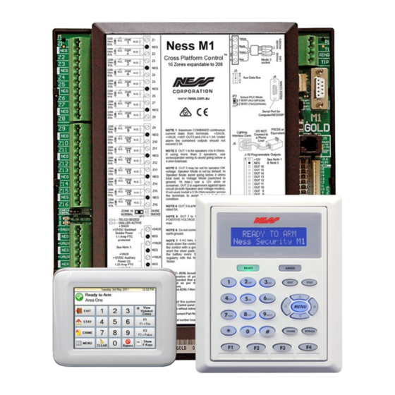
- Page 1 InstallatIon Manual M1 Cross Platform Control™ specifications, Installation and programming Rev 2.1...
- Page 2 LIMITATION The NESS ELK-M1G and ELK-M1 Controls are designed to warn against unauthorized entry and other situations. However, it is not a guarantee of protection against the occurrence of burglary, fire, or other emergency. Any alarm system is subject to compromise or failure to warn for various reasons.
-
Page 3: Table Of Contents
Section 3 - Programming The Control ..................... 21 3.1 Introduction ............................21 3.2 Local Keypad Programming ......................21 3.3 Local or Remote Computer Programming (Ness-RP) and Anti-Takeover ........21 3.4 Area Partitioning ..........................21 3.5 Communicator Setup Checklist ....................... 22 3.6 Entering Installer Level Programming .................... - Page 4 +VKP installed as per the filter's installation prot ected supply. Non-polarity guidelines. GREEN DATA A 16.5 V Use Ness ADSL Filters 100-044 or 100-045. WHITE DATA B BATTERY Power BLACK Data Bus Testing of this system should be performed See Note 1 Status regularly.
-
Page 5: Specifications, Features, And Benefits
����������������������������������������������� ������������������������������������������������������������������� ������������������������������������ ������������������������������������������������������������ ��������������������������������������������������� ����������������������������������������������������������� Communications ������������������������������������������������������� �������������������������������������������������������������� �������������������������������������������������������� ��������������������������������������������������������� ��������������������������������������������������������� �������������������������������������������� ��������������������������������������������������������� ������������������������������������������������������ ����������������������������������������������������������� ������������������������������������ Keypad options ������ ����������������������������������������������������� �������������������������� �������������������������� ���������������������� ������������������������������������������������������������� ����������������������������������������������������� ������������������������������������������������ ��������������������������������������������������� ��������������������������������������������������� ������������������������������������������� ����������������������������� NESS - M1 Installation and Programming Manual Page 5... -
Page 6: Wiring & Hookup Diagram
ONLY by momentarily shorting these two pads. Test battery regularly with ELK-BLT Battery Life Tester. Master Power Switch (SW1) , disconnects AC and Battery power from control Replace every 3-5 years NESS - M1 Installation and Programming Manual Page 6... - Page 7 Keypad 1 M1 Navigator and LCD keypads available Keypad 2 Keypad 3 NESS - M1 Installation and Programming Manual Page 7...
-
Page 8: Section 1 - Installation And Wiring
A central location makes running system wiring easier. Remove control box knockouts that best suit your wiring needs. Mount the control using the upper center slotted hole to level. Install and connect all necessary wiring for the power transformer, detection loops, keypads and siren outputs. NESS - M1 Installation and Programming Manual Page 8... -
Page 9: Control Wiring
Hookup Diagram for Keypad Splice 6 Pin Keypad Wiring Assembly to the Data Bus cable using ELK-900-2 "B" Connectors. Splice 6 pin Keypad wiring assembly to the Data cable using Ness 101-289 “B” connnectors See Note about Data Bus... - Page 10 The control maintains a float charge for the battery of 13.8 VDC at 100 mA. This is in addition to the continuous output of 1.5 Amps that the power supply maintains (see maximum current drains for UL Listed Systems). NESS - M1 Installation and Programming Manual Page 10...
- Page 11 Connection to the approved socket is done with a Ness Dialler cord (Part # 450 -200) which connects the control terminals to the mode 3 socket.
-
Page 12: Data Bus E.o.l. Termination - Very Important
BLUE BROWN See Diagram on next page for connection of Optional Output and Zone Input Diagram for Daisy Chain Connection of Data Bus Devices Using 3 or More Home Run Cables. Page 12 NESS - M1 Installation and Programming Manual... - Page 13 Bus Modules that are enrolled. To view the enrolled devices and/or remove a device press the XX Bus Modules RIGHT arrow key next to the word Edit. Enrolled, Edit r Press the * or Exit keys to exit Installer Programming. NESS - M1 Installation and Programming Manual Page 13...
-
Page 14: Section 2 - Operating The System
The installer code may also be used to silence a trouble condition in a disarmed area. See User’s Guide for a full description of arming and disarming procedures. The Factory Default Installer Program Code is: 1 7 2 8 3 9 NESS - M1 Installation and Programming Manual Page 14... -
Page 15: Keypad Overview
Once an option has been selected, the user may be prompted for a passcode. Additional sub-menu options may appear to assist. The user may return to the status screen by pressing the * key. NESS - M1 Installation and Programming Manual Page 15... -
Page 16: Keypad Menus
Lighting allows the individual control of lights and/or appliances which have been assigned 2-Lighting through the Ness-RP software. Press the RIGHT arrow key to select Lighting, then press the UP or DOWN arrow keys to scroll through the list. If you know the three digit number, you may enter it to jump directly to that Lighting/Appliance. - Page 17 DOWN keys. There are 9 backlight levels (1-9) plus Off (0). The keypad automatically dims to this Dim Level setting after 30 seconds of no activity in order to save energy. To exit press the * key. NESS - M1 Installation and Programming Manual Page 17...
- Page 18 Comm Fail trouble will occur. To clear a Comm Fail the dialer must be able to complete a good communication. To connect Ness’s Remote Program PC software (RP) via the user assisted method, press the 85-Connect ‘RP’...
- Page 19 (0) = No lockout, (1)=Lockout Telephone number programming - view everything, (2)=Lockout ALL programming - view everything, (3)=Lockout ALL Programming and Viewing. This can only be set or removed from the Ness- RP Remote Programming Software. NESS - M1 Installation and Programming Manual...
-
Page 20: Multi-Area (Partition) Operation
NOTE: This is a new feature which became available with firmware release version 4.2.5. The firmware may be flash upgraded in older controls to add this capability. NESS - M1 Installation and Programming Manual Page 20... -
Page 21: Section 3 - Programming The Control
3.1 Introduction The Security functionality of the M1 Control can be programmed either from an ELK-M1KP LCD Keypad OR from the NESS-RP PC Software. The keypad features a menu-driven “Text” based interface with simple Yes/No answers for most options. After just a short amount of experience the average installer will not even require an instruction manual to keypad program the control. -
Page 22: Communicator Setup Checklist
Under Menu 13 - User Report Codes, select and and program an Open or Close report code for any User(s) that you wish to track arm/disarm events, including arm/disarm by the Installer Code or Ness-RP computer. 3.6 Entering Installer Level Programming Press the center ‘ELK’... - Page 23 NESS - M1 Installation and Programming Manual Page 23...
-
Page 24: Menu 01 - Bus Module Enrollment
NOTE: If a device is removed from the data bus, it should be un-enrolled to prevent a trouble. To replace a defective device, set the address to the same value as the old unit and initiate the Bus Enrollment process. NESS - M1 Installation and Programming Manual Page 24... -
Page 25: Menu 02 - User Code Options
A Yes allows this code to activate the Access Keypad Events 1313-1328 for the keypad 001 05:=No where code is entered. Use the Whenever/And/Then Rules from Ness-RP to assign an Access with Code output to this event for tripping a door strike or lock. Note: If this code is enabled for arming, it will be necessary to press the Exit or Stay key to arm after the code. -
Page 26: Menu 03 - Area Definitions
An Exit Error event flag will also be set which can be used by the “Whenever/And/Then” rules (refer to the Ness-RP software) to sound a siren, or blink a light, or whatever. Exit Error feature complies with the SIA CP-1 false alarm reduction standard. - Page 27 AUTO ARMING: The control has an Auto Arming feature which may be setup using the “Whenever/And/Then Rules” in the Ness-RP PC Programming Software. Basically, a rule must be written to initiate the auto arm sequence at a specific time and/or date occurrence along with a programmable pre-warning time period. At the end of the pre-warn time, the system will automatically arm to the AWAY mode, bypassing any violated Burglar zones.
-
Page 28: Menu 04 - Keypad Definitions
This serves to visually verify to the user that the correct key has been selected prior to the second “activating” key press. 7) Key Name - A sixteen character programmable description that describes the key’s function. I.E. Police Alarm, Garage Door, etc. NESS - M1 Installation and Programming Manual Page 28... - Page 29 Automation Task, or by Ness-RP Whenever/And/Then Rules to activate most Evt=Fire Alarm anything. Press the RIGHT arrow key and enter 4 digits. Enter 0000 if Ness-RP is going to be used exclusively. Enter 0001-0036 for an alarm activation (see zone Defs), or 2001-2032 for an automation task activation (see Ness-RP software).
-
Page 30: Menu 05 - Zone Definitions
It is displayed in the event log. A Whenever/And/Then rule can be written from the RP software to do other things with this zone type. Resets upon restoral. NESS - M1 Installation and Programming Manual Page 30... - Page 31 Low Battery event and open the zone in an AC Failure event. 33 Temperature - For use with M1ZTS Temperature Sensors.(Ness part # 101-229 & 101-230) Requires the use of Whenever/And/Then rules from the Ness-RP software.
- Page 32 Enable Listen-In The Central Station can renew or terminate listen-in remotely. NOTE: Two-Way must be enabled (Menu 07-Globals) and an interface (Ness-M1TWI Part # 101-216) with one or more microphone/speakers (Ness-M1TWS part # 101-219) must be installed. Default setting is No.
-
Page 33: Menu 06 - Alarm Duration Timers
Aux 2 Alarm duration time in seconds. The default time is 00600 sec. (10 min.). This CT12:=00600 sec alarm type is not preassigned to any outputs. The RP software “Rules” function must be Aux2Duration used to assign outputs. NESS - M1 Installation and Programming Manual Page 33... -
Page 34: Menu 07 - Global System Definitions
1 minute after a sequence of invalid WrongCodeLockout digits. The range of value can be set from 13 to 99. Default is 99. NESS - M1 Installation and Programming Manual Page 34... - Page 35 G24:=Yes Out1 Selects whether Zone Trouble messages will be spoken through Output 1. Say Zone Trouble G25:=Yes Out1 Selects whether Chime Event messages will be spoken through Output 1. Say Chime NESS - M1 Installation and Programming Manual Page 35...
- Page 36 NOTE: If an on-site answering machine picks up, the RP software and the control will automatically attempt to override the machine using tone sniffing methods. Set this option to Yes ONLY when an M1TWI Two Way Listen-In interface (Ness part # G31:=No 2Way 101-216) is installed.
- Page 37 Entering 94 from this screen causes all voice messages to be factory defaulted. 95=WirelessDef Entering 95 from this screen causes all wireless definitions to be factory defaulted. 99=Entire Panel Entering 99 from this screen causes the entire panel programming to be factory defaulted. NESS - M1 Installation and Programming Manual Page 37...
-
Page 38: Menu 08 - Telephone Account Setup
Account Setup Telephone Acct Setup Description of Option The ELK-M1 provides up to 4 regular phone numbers plus 1 number for Ness-RP remote T1: Sel programming software. The ELK-M1G (Gold) provides up to 8 regular phone numbers plus [Name for Tel#1] the Ness-RP number. - Page 39 While programming the text, pressing the Chime key inserts a space, and the Bypass key erases 1 digit. The up and down arrow keys toggles between upper and lower case. Press the ELK key when complete. NESS - M1 Installation and Programming Manual Page 39...
-
Page 40: Menu 09 - Area Reporting Codes
Close Extended code will be reported if a programmed Expected Arm time is extended by AR1 07:Code= 00 a valid user. Refer to the Ness-RP Rules Programming instructions. Range is 00 to FF. Close Extended Default is 00 (no report). - Page 41 Open Early code will be reported if the area is disarmed prior to a programmed Expected AR1 13:Code= 00 Disarm time. Refer to the Ness-RP Rules Programming instructions. Range is 00 to FF. Open Early Default is 00 (no report).
-
Page 42: Menu 10 - Zone Reporting Codes
---- ---- ---- ---- ---- ---- ---- ---- 18 = Gen Pur. Do Nothing ---- ---- ---- ---- ---- ---- ---- ---- 36 = Intercom Key ---- ---- ---- ---- ---- ---- ---- ---- NESS - M1 Installation and Programming Manual Page 42... -
Page 43: Menu 11 - Keypad F-Key Reporting Codes
32 = Power Supervisory 1338 YT 15 = Keyfob ---- ---- 33 = Temperature ---- ---- 16 = Non-Alarm ---- ---- 34 = Analog ---- ---- 17 = Carbon Monoxide 1162 GA NESS - M1 Installation and Programming Manual Page 43... -
Page 44: Menu 12 - Sys Report Code Options & Codes
Log 80% Full will be reported whenever the Event Log becomes 80% full. Range is 00 to SR10: 00= Log FF. Default is 00 (no report). The Ness-RP is required to download the log and/or clear it. 80% Full NESS - M1 Installation and Programming Manual... - Page 45 Expansion Module Trouble 1333 Telephone Line Fault 1351 Expansion Module Restore 3333 Telephone Line Restore 3351 Local Programming Begin 1627 Output 2 Trouble 1322 Local Programming End 1628 Output 2 Restore 3322 NESS - M1 Installation and Programming Manual Page 45...
-
Page 46: Menu 13 - User Report Codes
The next press of the right arrow key will advance back to the beginning screen. UR100:O=00 C=00 Installer Op/Close UR101:O=00 C=00 Up/Dnload Op/Cl The CID (Contact ID) or SIA Codes for User Reporting Codes are: User RCs Open 1401 Close 3401 NESS - M1 Installation and Programming Manual Page 46... -
Page 47: Menu 14 - Wireless Definitions
Menu 14 - Wireless Definitions 1 4 - W i r e l e s s For details refer to the Ness M1 Radio Receiver Manual. Definitions NESS - M1 Installation and Programming Manual Page 47... - Page 48 [Intentionally left blank] NESS - M1 Installation and Programming Manual Page 48...
-
Page 49: Section 4 - Pc Programming And Automation Capabilities
Connection, and RP will pick up the line and enter the access codes required to connect with the control. 3. Network - With an optional M1XEP Ethernet Port module (Ness part # 101-215) you can connect over a Local or Wide Area Network. -
Page 50: Update/Verify Firmware In The Control And Peripherals
IC chips or shipping boards back to the factory. As new firmware updates become available, they will be posted on Ness’s website [www.ness.com.au/m1] in a password restricted “M1 Dealers ONLY” location. NOTE: Firmware updating can only be done from a Direct to PC Com port connection or an optional Ethernet Network connection. -
Page 51: Automation Rules And Attributes
4.3 Automation Rules and Attributes The Ness-M1, together with the RP Automation Programming software offers powerful, easy to setup and manage, life style enhancement features. The automation programming allows mixing and matching of lighting components, outputs (relays or voltage), thermostats, temperature sensors, and all the security inputs and features to integrate functions that add value and appeal to the owner/user. - Page 52 “standard time”. Therefore, the calculated times will reflect standard time. If the control is set for “Observe Daylight Savings Time” the sunrise/sunset times will be adjusted by the control accordingly. NESS - M1 Installation and Programming Manual Page 52...
- Page 53 There are a total of 64 counters. Each can be programmed with a 12 character description, making it easy to reference in an automation rule. NESS - M1 Installation and Programming Manual Page 53...
- Page 54 RCS, Aprilaire, and HAI. Due to the various data protocols, a Lighting/Thermostat/Serial Interface Expander (M1XSP- ness part # 101-214) is needed to couple the M1 data bus to HVAC thermostats. Depending on the brand of thermostat, its wiring interface (RS-232 or RS-485), and the model of M1 that you are installing, up to 16 HVAC thermostats can be controlled.
- Page 55 “BECOMES”, which clearly implies that the event has to change from its current condition and “become” the alternate condition. Just remember, a rule can only be triggered by the transition of an event from one condition to another. NESS - M1 Installation and Programming Manual Page 55...
- Page 56 WHENEVER trigger an AND to test the door’s open/closed state, and a THEN to turn off the output that controls the air condition. WHENEVER EVERY 30 SECONDS AND Front Door (Zn 1) IS NOT SECURE THEN TURN Air Cond (Out 9) OFF NESS - M1 Installation and Programming Manual Page 56...
- Page 57 Rule 9 makes the siren chirp twice if the control disarms when the user presses button 2 Rule 10 makes the siren chirp four times (error tone) if the control fails to arm when the user presses button 1. NESS - M1 Installation and Programming Manual Page 57...
-
Page 58: Appendix A - Event Codes
1061 = CO Alarm in Area 7 1124 = Keypad 13 Code-Lockout 1062 = CO Alarm in Area 8 1125 = Keypad 14 Code-Lockout 1126 = Keypad 15 Code-Lockout 1127 = Keypad 16 Code-Lockout NESS - M1 Installation and Programming Manual Page 58... - Page 59 Event clears upon User Code entry A (16) Event clears upon Arming D (32) Event clears upon Disarming B (64) Event clears almost immediately “Blip” F (128) Event toggles with each activation NESS - M1 Installation and Programming Manual Page 59...
-
Page 60: Appendix B - Telephone Remote Control
Add 0’s in front of numbers single digits. NOTE: Any valid sensor entering it’s two digit number, even if it was not announced. The sensor name will then be repeated along with it’s current reading. NESS - M1 Installation and Programming Manual Page 60... - Page 61 For Audio Alert press 7. This only works if a 2 way listen-in interface is installed. (Ness-M1TWI part # 101-217) It will open an audio path from the phone to the listen-in board and the output 1 speakers. For full operating instructions see Appendix D.
-
Page 62: Appendix C - Voice Message Vocabulary *Rp Only
Disarmed = 144 Hanging up = 204 Living room = 264 Away = 83 Dock = 145 Hang up = 205 Loading = 265 Door = 146 Has = 206 Lobby = 266 NESS - M1 Installation and Programming Manual Page 62... - Page 63 [Say Secure/Not Secure] = 506 Panic = 324 Shorted = 388 Visitor = 450 [Say Unlocked/Locked] = 495 Parking = 325 Shunted = 389 [Say Up/Down] = 508 Partition = 326 Side = 390 NESS - M1 Installation and Programming Manual Page 63...
-
Page 64: Appendix D - Two Way "Listen-In/Talk" Interface (Optional)
Appendix D - Two Way “Listen-in/Talk” Interface (optional) Using a Two Way Interface board (Ness-M1TWI, part # 101-217), the M1 accommodates up to 3 zones of listen-in. Each zone can have up to 4 microphones for a total of 12 listen-in points. Talk back is delivered through the speakers connected to Output 1. -
Page 65: Appendix E - Sia Cp-01 Compliance
* Programming at installation may be subordinate to other UL requirements for the intended application. ** Combined Entry Delay and Abort Window should not exceed 1 minute. *** Feature is pre-defined in the panel software and may not be altered. NESS - M1 Installation and Programming Manual Page 65... -
Page 66: Appendix F - Regulatory Agency Statements
If this happens, the telephone company will provide advance notice in order for you to make the necessary modifications in order to maintain uninterrupted service. If trouble is experienced with this equipment, please contact Ness for repair and warranty information. Ness Security Products, 4 / 167 Prospect Hwy, Seven Hills, NSW, 2147 (02) 8825 9222. - Page 67 [Intentionally left blank] NESS - M1 Installation and Programming Manual Page 67...
-
Page 68: Appendix G - Additional Keypad Information
An Access event occurs when a valid prox card/fob is read at a keypad. It will not do anything unless included in a Whenever/And/Then Rule from the Ness-RP software. An Access event can be used to create virtually any desired reaction. - Page 69 To make a warranty claim, the product should be returned to any Ness Corporation branch; details of which appear on the ness Corporation web site. the product must be returned with the installer’s fault report clearly stating the company name and contact details of the purchaser, the date of purchase, product serial number/s (if any), the original invoice number and a detailed fault description.
-
Page 70: Index
Zone Wiring Types 31 Force Arm 32 Regulatory Agency Statements - Appendix F 66 Ring/Hang/Answer option 36 Global Sys Definitions 34, 35, 36, 37 Rings Until Auto Answer 37 RP Software 49 Page 70 NESS - M1 Installation and Programming Manual... - Page 71 improvement.
Need help?
Do you have a question about the M1 Cross Platform Control and is the answer not in the manual?
Questions and answers