
Subscribe to Our Youtube Channel
Related Manuals for Moxa Technologies ioLogik E2200Series


Summary of Contents for Moxa Technologies ioLogik E2200Series
- Page 1 ioLogik E2200 Series User’s Manual Edition 6.5, November 2016 www.moxa.com/product © 2016 Moxa Inc. All rights reserved.
-
Page 2: Copyright Notice
ioLogik E2200 Series User’s Manual The software described in this manual is furnished under a license agreement and may be used only in accordance with the terms of that agreement. Copyright Notice © 2016 Moxa Inc. All rights reserved. Trademarks The MOXA logo is a registered trademark of Moxa Inc. -
Page 3: Table Of Contents
Table of Contents Introduction ............................1-1 Product Key Features and Highlights ..................... 1-2 Package Checklist ..........................1-2 Product Model Information ........................1-2 Product Selection Guide ........................1-3 Product Specifications ......................... 1-4 Common Specifications ........................ 1-4 ioLogik E2210 Specifications ......................1-5 ioLogik E2212 Specifications ...................... - Page 4 Click&Go Logic Basics .......................... 4-3 Working with Rules ..........................4-4 Click&Go Development Process ......................4-4 I/O Configuration ..........................4-5 Digital Input Mode Selection ......................4-5 Digital Output Mode Selection ....................... 4-6 Analog Input Mode Selection......................4-6 Alias Name Configuration ......................4-6 Testing the I/O Channels ......................
- Page 5 LCM Controls ............................A-2 LCM Options............................A-2 Used Network Port Numbers ......................B-1 ioLogik E2200 Smart Ethernet Remote I/O Device Network Port Usage ............B-1 Factory Default Settings ........................C-1 Cable Wiring ............................D-1 Device Wiring Diagrams ........................D-2 Analog Input ..........................D-2 Analog Output ...........................
-
Page 6: Introduction
Introduction The ioLogik E2200 series is a standalone Smart Ethernet remote I/O device that can connect sensors and on/off switches for automation applications over Ethernet and IP-based networks. The following topics are covered in this chapter: Product Key Features and Highlights ... -
Page 7: Product Key Features And Highlights
ioLogik E2200 Series Introduction Product Key Features and Highlights 1. Front-end intelligence that supports 24 Click&Go rules 2. Active Messaging with real-time stamp, including SNMP Trap with I/O status, TCP, and e-mail. 3. Supports SNMPv1/v2c/v3 protocol 4. I/O peer-to-peer function 5. -
Page 8: Product Selection Guide
ioLogik E2200 Series Introduction Product Selection Guide The operating temperature for standard models is -10 to 60°C. The operating temperature for wide temperature models is -40 to 75°C Digital Selectable Digital Relay Analog Analog Inputs Outputs Outputs Inputs Outputs Inputs Inputs E2200 Series Common Specification... -
Page 9: Product Specifications
ioLogik E2200 Series Introduction Product Specifications Common Specifications Ethernet: 1 x 10/100 Mbps, RJ45 Protection: 1.5 kV magnetic isolation Protocols: Modbus/TCP, TCP/IP, UDP, DHCP, Bootp, SNMP, HTTP, CGI, SNTP, SMTP Serial Communication Interface: RS-485-2w: Data+, Data-, GND (3-contact terminal block) Serial Line Protection: 15 kV ESD for all signals Serial Communication Parameters Parity: None... -
Page 10: Iologik E2210 Specifications
ioLogik E2200 Series Introduction ioLogik E2210 Specifications Inputs and Outputs Digital Inputs: 12 channels Digital Outputs: 8 channels Isolation: 3K VDC or 2K Vrms Digital Input Sensor Type: Wet Contact (NPN), Dry Contact I/O Mode: DI or Event Counter Dry Contact: •... -
Page 11: Iologik E2212 Specifications
ioLogik E2200 Series Introduction ioLogik E2212 Specifications Inputs and Outputs Digital Inputs: 8 channels Digital Outputs: 8 channels Configurable DIOs: 4 channels Isolation: 3K VDC or 2K Vrms Digital Input Sensor Type: Wet Contact (NPN or PNP) and Dry Contact I/O Mode: DI or Event Counter Dry Contact: •... -
Page 12: Iologik E2214 Specifications
ioLogik E2200 Series Introduction ioLogik E2214 Specifications Inputs and Outputs Digital Inputs: 6 channels Relay Outputs: 6 channels Isolation: 3K VDC or 2K Vrms Digital Input Sensor Type: Wet Contact (NPN or PNP) and Dry Contact I/O Mode: DI or Event Counter Dry Contact: •... -
Page 13: Iologik E2240 Specifications
ioLogik E2200 Series Introduction ioLogik E2240 Specifications Inputs and Outputs Analog Inputs: 8 channels Analog Outputs: 2 channels Analog Input Type: Differential input Resolution: 16 bits I/O Mode: Voltage / Current Input Range: ±150 mV, ±500 mV, ±5 V, ±10 V, 0 to 20 mA, 4 to 20 mA Accuracy: ±0.1% FSR @ 25°C ±0.3% FSR @ -10 and 60°C... -
Page 14: Iologik E2242 Specifications
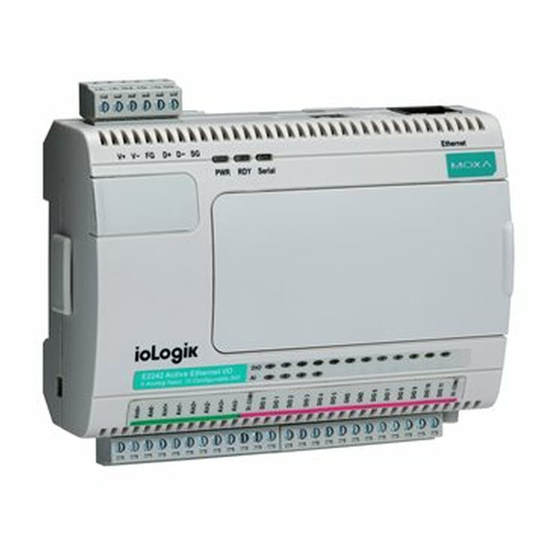
ioLogik E2200 Series Introduction ioLogik E2242 Specifications Inputs and Outputs Analog Inputs: 4 channels Configurable DIOs: 12 channels Analog Input Type: Differential input Resolution: 16 bits I/O Mode: Voltage / Current Input Range: ±150 mV, 0 to 150 mV, ±500 mV, 0 to 500 mV, ±5 V, 0 to 5 V, ±10 V, 0 to 10 V, 0 to 20 mA, 4 to 20 mA Accuracy: ±0.1% FSR @ 25°C... -
Page 15: Iologik E2260 Specifications
ioLogik E2200 Series Introduction ioLogik E2260 Specifications Inputs and Outputs RTD Inputs: 6 channels Digital Outputs: 4 channels Isolation: 3K VDC or 2K Vrms RTD Inputs Input Type: PT50, PT100, PT200, PT500, PT1000; JPT100, JPT200, JPT500, JPT1000; NI100, NI120, NI200, NI500, NI1000;... -
Page 16: Iologik E2262 Specifications
ioLogik E2200 Series Introduction ioLogik E2262 Specifications Inputs and Outputs Thermocouple Inputs: 8 channels Digital Outputs: 4 channels Thermocouple Input Sensor Type: J (0 to 750°C), K (-200 to 1250°C), T (-200 to 350°C), E (-200 to 900°C), R (-50 to 1600°C), S (-50 to 1760°C), B (600 to 1700°C), N (-200 to 1300°C) Millivolt Type: •... -
Page 17: Physical Dimensions
ioLogik E2200 Series Introduction Physical Dimensions Without LCM Unit = mm With LCM Unit = mm 1-12... -
Page 18: Hardware Reference
ioLogik E2200 Series Introduction Hardware Reference Panel Guide NOTE The RESET button restarts the device and resets all settings to factory defaults. Use a pointed object such as a straightened paper clip to hold the RESET button down for 5 sec. The RDY LED will turn red as you are holding the RESET button down. -
Page 19: Led Indicators
ioLogik E2200 Series Introduction TB1 (Power Input & RS-485 Connector) Signal (V+: 12 to 36 VDC) TB2 (Input and Output Terminal) Refer to the Appendix F. LED Indicators Light Description System power off System power on System not ready Green System ready System error Green Blinking... -
Page 20: Initial Setup
Initial Setup This chapter describes how to install the ioLogik E2200 series. The following topics are covered in this chapter: Hardware Installation Connecting the Power Grounding the Unit Software Installation Restore Factory Defaults Connecting to ioAdmin via Ethernet ... -
Page 21: Hardware Installation
ioLogik E2200 Series Initial Setup Hardware Installation Connecting the Power Connect the 12 to 36 VDC power line to the ioLogik’s terminal block (TB1). If power is properly supplied, the power LED will glow a solid red color. ATTENTION Determine the maximum possible current for each power wire and common wire. Observe all electrical codes dictating the maximum current allowable for each wire size. - Page 22 ioLogik E2200 Series Initial Setup NOTE The best approach to setting up a previously configured ioLogik is to reset it to the factory default using the RESET button (see Chapter 1). You can then use the ioAdmin utility to configure the ioLogik. NOTE If the host computer has multiple network interfaces, be sure to select the correct interface before searching.
-
Page 23: Restore Factory Defaults
ioLogik E2200 Series Initial Setup Restore Factory Defaults There are three ways to restore the ioLogik to factory default settings. 1. Hold the RESET button for 5 seconds. 2. Right-click on the specifc ioLogik in the ioAdmin utility and select Reset to Default. 3. -
Page 24: Activating Ioadmin And Connecting To The Iologik
ioLogik E2200 Series Initial Setup Activating ioAdmin and Connecting to the ioLogik 1. Open ioAdmin: Click Start Program Files MOXA IO Server Utility ioAdmin. 2. Search the network for the ioLogik: When ioAdmin is started, it will automatically run the auto search program. - Page 25 ioLogik E2200 Series Initial Setup NOTE If multiple ioLogik devices with the same default IP address are installed on the same network, assign a different IP address to each device to avoid IP conflicts. ioAdmin automatically detects IP address conflicts for each device so you can modify conflicting IP addresses in the IP Address column, as shown below.
- Page 26 ioLogik E2200 Series Initial Setup 5. Monitoring and Testing I/O statuses: Once your unit has been detected by ioAdmin, you can view the status of all connected I/O modules and devices on the ioAdmin main screen. NOTE ioAdmin supports four viewing options for the navigation panel. If you select Sort by Active OPC Server, the ioLogik will appear in the Active OPC Server group.
-
Page 27: Adding More I/O Channels
ioLogik E2200 Series Initial Setup After clicking the Test tab, you can see how a channel’s status affects or is affected by the attached device. For DO channels, you can set the ON/OFF status or START/STOP pulse output. For DI channels, you can monitor the attached devices’... -
Page 28: Setting The Rs-485 Baudrate
ioLogik E2200 Series Initial Setup ATTENTION All I/O channels of the ioLogik E2200+R2140 system can be polled by a remote host PC, but Click&Go logic can only be used with the ioLogik E2200 series. Currently, Click&Go local control logic is not supported by the ioLogik R2140 series. - Page 29 ioLogik E2200 Series Initial Setup NOTE It is strongly recommended to have a contact protection circuit for the relay output. A varistor can serve as a contact protection circuit where the parallel circuit connects with the load. Load NOTE A “load” in a circuit schematic is a component or portion of the circuit that consumes electric power. For the diagrams shown in this document, “load”...
-
Page 30: Using Ioadmin To Import/Export Configurations
ioLogik E2200 Series Initial Setup ATTENTION—Dry Contacts When connecting an I/O device to the ioLogik’s dry contacts, connect DI.COM to the power of the external sensor to avoid affecting other channels. The DI.COM input power should be between 12 to 36 VDC. ATTENTION—DIO Channels Sensor types are grouped, with DIO-0 to DIO-5 forming one group and DIO-6- to DIO-11 forming another group. - Page 31 ioLogik E2200 Series Initial Setup ATTENTION Since there are major functional differences between firmware versions, exporting the configuration file requires a longer processing time. Adjust the TCP Socket Timeout Interval to 30 seconds when using ioAdmin 3.10 or above, especially if earlier versions of ioAdmin have been installed and then removed. Import System Config Select this command to load a configuration for the selected ioLogik from a configuration text file.
-
Page 32: Using Ioadmin
Using ioAdmin In this chapter, we explain how to use ioAdmin to configure your ioLogik product. The following topics are covered in this chapter: System Requirements Features of ioAdmin ioAdmin Overview Main Screen Overview Title ... -
Page 33: System Requirements
ioLogik E2200 Series Using ioAdmin System Requirements The ioLogik E2200 series device can be managed and configured by Ethernet with the ioAdmin Windows utility. ioAdmin’s graphical user interface provides easy access to all status information and settings. ioAdmin can also be used to configure Click&Go rules to handle front-end events. -
Page 34: Ioadmin Overview
ioLogik E2200 Series Using ioAdmin Server Management List ioAdmin can import and export a list of ioLogik units that are being managed. This file can make it easier to manage all devices on the network, and includes the following information: •... -
Page 35: Title
ioLogik E2200 Series Using ioAdmin Title The Title shows you which program is opened. In this case, it indicates that Moxa ioAdmin is running. Menu Bar The Menu bar has four items: File System Sort Help File From the File menu, you can export the list of ioLogiks currently displayed in the navigation panel. You can also import a list into ioAdmin. - Page 36 ioLogik E2200 Series Using ioAdmin System Several operations can be accessed from the System menu. Auto Scan ioLogik Devices The Auto Scan ioLogik Devices function searches for ioLogiks on the network automatically. When connecting for the first time, or when recovering from a network disconnection, you can use this command to find any ioLogik that is connected to the physical network.
-
Page 37: Network Interface
ioLogik E2200 Series Using ioAdmin Network Interface Network Interface allows you to select a network interface to use (if the PC has multiple network adaptors installed). The default network interface will be the same as the Windows setting. Make sure the interface is correct when connecting to the ioLogik device;... - Page 38 ioLogik E2200 Series Using ioAdmin COM Port Setting This operation is used to set the default parameters for the ioAdmin utility to establish a Modbus connection, such as baudrate, data bits, and timeout interval. For most applications, this will involve connecting to ioLogik R-series devices.
- Page 39 ioLogik E2200 Series Using ioAdmin Sort The Sort menu allows the Devices list in the navigation panel to be sorted by connection, model, location, or Active OPC. Help In the Help menu, you can view wiring guides and information about ioAdmin.
- Page 40 ioLogik E2200 Series Using ioAdmin Wiring Guides ioAdmin provides a wiring guide for the ioLogik E2200 series. You can access the wiring guide by right-clicking the ioLogik figure in the I/O Configuration tab. Select “Wiring Guide” in the submenu to open a help file showing the unit’s wiring information and electrical characteristics (or refer to cable wiring).
-
Page 41: Quick Links
ioLogik E2200 Series Using ioAdmin Quick Links Quick Links toolbard contains a collection of commonly used functions, including the Search and the Sort functions. Auto Scan ioLogik Devices This icon provides a direct link to start running the Auto Scan ioLogik Devices function. Sorting Methods These icons allow you to sort the ioLogik devices viewed in the Navigation Panel according to the following criteria:... - Page 42 ioLogik E2200 Series Using ioAdmin Basic Functions: Add, Connect, and Disconnect Add ioLogik ioLogik device: Select ioLogik tag and right click the tag. Select the “Add ioLogik device” command to add an ioLogik device or Active OPC server manually. Connect: Select the “Connect” command to try connecting over the network to the selected ioLogik. Disconnect: Select the “Disconnect”...
-
Page 43: Main Window
ioLogik E2200 Series Using ioAdmin Main Window I/O Configuration Tab (General) The I/O Configuration tab shows the status of every I/O channel. This is the default tab when you first open ioAdmin. Input channels are listed on the left and output channels are listed on the right. Server Info Tab Server information, such as firmware version, is displayed in the Server Info tab. - Page 44 ioLogik E2200 Series Using ioAdmin Server Settings Tab (General) The Server Settings tab is where you log in as an ioAdmin administrator. This is required in order to gain access to the ioLogik configuration options. If a password has not been configured, simply click Login and leave the Password entry field blank.
-
Page 45: Sync Rate Status
ioLogik E2200 Series Using ioAdmin Messages can be displayed in ASCII or in HEX. To display messages in HEX, make sure that “Toggle HEX” is checked. Sync Rate Status The current sync rate is displayed on the bar at the bottom of the window. The number shows how often the ioLogik is polled for device status from the ioAdmin utility. -
Page 46: I/O Configuration Tab (Administrator)
ioLogik E2200 Series Using ioAdmin I/O Configuration Tab (Administrator) When logged in as an administrator, double-click on a channel in the I/O Configuration tab to configure that channel’s settings. A window will open with configuration options for that channel. After configuraing the channel as desired, click Apply to implement the new settings. - Page 47 ioLogik E2200 Series Using ioAdmin Configuring Analog Input Channels The ioLogik analog input channels can be configured individually, or you can set all channels at the same time by selecting the Apply to all channels checkbox. To increase the sampling rate, disable any unused AI channels by deselecting the Enable Channelcheckbox. Select the Enable Auto Scaling checkbox to linearly convert the actual current or voltage value into other user defined units, such as percentage or ppm (parts per million).
- Page 48 ioLogik E2200 Series Using ioAdmin Two math formulas are used to convert actual values and user-defined units: (1) the point-slope formula and (2) the slope-intercept formula. 1. Auto Scaling by the point-slope formula Auto Scaling by the point-slope formula can help eliminate high end and low end extremes. For example, a temperature reading of 17 mA is already dangerously high, so there would be no need to wait for a higher temperature reading before responding.
- Page 49 ioLogik E2200 Series Using ioAdmin The Reset Min and Reset Max buttons will clear the minimum or maximum values recorded and displayed in the ioAdmin main window. Configuring Analog Output Channels The ioLogik device’s analog output (AO) range can be set to either 0–10 V or 4–20 mA. You may also configure all channels at the same time by selecting the Apply to all channels checkbox.
- Page 50 ioLogik E2200 Series Using ioAdmin AO Test: Use this tab to test the AO channel. Note that the slider shows both the raw data value and the engineering value (V/mA). You may use this as a guide when entering values for the Power On and Safe Status settings. Alias Name Click the Alias Name tab to customize the channel name.
- Page 51 ioLogik E2200 Series Using ioAdmin Configuring Selectable DIO Channels Channels DIO-0 to DIO-11 support both DI and DO channel operations. When the ioLogik E2200 unit is turned on, each DIO channel will be configured to act as either a DI or DO channel, according to the Power On Settings.
- Page 52 ioLogik E2200 Series Using ioAdmin Configuring Digital Input Channels The ioLogik E2210 can support up to 12 digital input (DI) channels. Software filtering is used to control switch bounces. Under 1. Mode Settings, the Filter field is configurable in multiples of 0.5 ms and accepts values between 1 and 65535.
- Page 53 ioLogik E2200 Series Using ioAdmin Configuring Digital Output / Relay Output Channels The ioLogik E2200 series digital output and relay output channels can be set to “DO” or “Pulse Output” mode. In DO mode, the specifications are as follows. Type DO mode Open Short...
- Page 54 ioLogik E2200 Series Using ioAdmin Testing DI and DO Channels You can test each channel by opening the channel’s configuration window and selecting the Test tab. On the Test tab, you can see how a channel’s status affects or is affected by the attached device. For DO channels, you can set the on/off status or start and stop pulse output.
- Page 55 ioLogik E2200 Series Using ioAdmin You can control how a DO/Relay output channel acts when the network is disconnected by using the Safe Status Settings and the Host Connection Watchdog. When the Host Connection Watchdog is enabled, a network disconnection will activate the Safe Status Settings. The DO channel can be configured to turn on, turn off, or commence pulse output.
- Page 56 ioLogik E2200 Series Using ioAdmin Configuring RTD Input Channels The ioLogik E2260 provides 6 fixed physical RTD input (Resistance Temperature Detector) channels, each supporting up to 18 different types including PT50, PT100, JPT100, and more. The RTD channels are numbered from channel 0 to channel 5.
-
Page 57: Virtual Channels
ioLogik E2200 Series Using ioAdmin Virtual Channels The ioLogik E2260 provides virtual channels so you can easily determine the average or deviation values for any attached temperature sensor. A virtual channel can operate in Average Mode or Deviation Mode. In Average Mode, up to 6 physical channels are selected and the virtual channel reports the average value of the selected channels. - Page 58 ioLogik E2200 Series Using ioAdmin Virtual Channels The ioLogik E2262 provides virtual channels so you can easily determine the average or deviation values for any attached temperature sensor. A virtual channel can operate in Average Mode or Deviation Mode. In Average Mode, up to 8 physical channels are selected and the virtual channel reports the average value of the selected channels.
-
Page 59: Server Settings Tab (Administrator)
ioLogik E2200 Series Using ioAdmin Server Settings Tab (Administrator) You may set the password (up to 16 characters), server name, location, date, time, time zone, and time server in the Server Settings tab. ioAdmin supports long server names and a location description with up to 58 characters. -
Page 60: Network Tab
ioLogik E2200 Series Using ioAdmin If you will be using ioEventLog to receive server status reports, such as for warm or cold starts, you need to specify the IP address and port number for the PC that will be running ioEventLog in the “System Log” field. The default port number is 4040. -
Page 61: Firmware Update Tab
ioLogik E2200 Series Using ioAdmin DNS Settings Use this field to specify the IP addresses of one or two DNS servers. DNS servers can be used to find available e-mail addresses when setting up Click & Go rules. Serial Settings You can view the reserved RS-485 communication parameters here, and set the timeout value for breaks in RS-485 communication. -
Page 62: Watchdog Tab
ioLogik E2200 Series Using ioAdmin Watchdog Tab The Watchdog panel is available after you log in as administrator. When enabled, the Host Connection Watchdog monitors the network connection. If the connection is lost for the specified Timeout value, the Watchdog will display a warning and activate the Safe Status settings for each DO channel and Event Counter channel. -
Page 63: Click&Go Logic Tab
ioLogik E2200 Series Using ioAdmin Click&Go Logic Tab The Click&Go Logic tab is available after logging in as an administrator. This is where the ioLogik’s device system is configured. With a set of rules (known as a ruleset) defined through Click&Go, the ioLogik can report I/O status to a host as soon as user-defined I/O conditions have been met. -
Page 64: Active Tags Tab
ioLogik E2200 Series Using ioAdmin Active Tags Tab When logged in as administrator, fill in the fixed IP address on the Active Tags panel to configure the Active OPC Address and Port settings. The Active OPC Server Address can be filled in using the IP or DNS format. The default port number is 9900. - Page 65 ioLogik E2200 Series Using ioAdmin Heartbeat Interval Tags are event-driven and updated only when the status of an I/O channel changes, so when the status remains unchanged, they will not be updated to Active OPC Server. The Heartbeat Interval can be used to determine the connection status between the ioLogik and Active OPC Server, and to ensure that the ioLogik is connected and live.
- Page 66 ioLogik E2200 Series Using ioAdmin Active Tags A tag selection table shown in the right panel of the browser window shows the details of your selection. The I/O status of a channel can be updated to the Active OPC Server once it is changed, or updated periodically. 1.
-
Page 67: Snmp Settings Tab
ioLogik E2200 Series Using ioAdmin SNMP Settings Tab The ioLogik supports SNMP V1, V2c, and V3 (Simple Network Management Protocol) to monitor network and I/O devices with SNMP Network Management software. It is useful in building automation and telecom applications. Use these fields to enable SNMP and set the read and write community strings for SNMP V1 and V2c, or use authentication for SNMP V3. -
Page 68: Message Monitor Panel (General)
ioLogik E2200 Series Using ioAdmin Message Monitor Panel (General) The Message Monitor panel will display any TCP/UDP Active Messages reported by the ioLogik. When you install the unit for the first time, the ruleset will not have been defined yet, so there will be no messages on the Message Monitor Panel. -
Page 69: Server Context Menu
ioLogik E2200 Series Using ioAdmin Server Context Menu The Server context menu is accessed by right clicking on the server model name in the navigation panel. Connect Select this command to try connecting over the network to the selected ioLogik. Disconnect Select this command to drop the network connection with the selected ioLogik. - Page 70 ioLogik E2200 Series Using ioAdmin ioLogik E2242 Network I/O Server Configuration ============================================== [System Information] Date: 2010/04/07 Time: 06:10:56 Firmware: V3.4 Build10032218 Click&Go=2.1 MOS= V3.2.34 [1. Model] ---------- MOD_TYPE=E2242 - Active Ethernet I/O Server (12DIO + 4AI) MOD_LOC= MOD_NAME= [2. I/O Configurations] ----------------------- DI00=1,(Counter), DI00_PWN=0,(Stop), DI00_SAFE=0,(Stop),...
-
Page 71: Using Ioeventlog
ioLogik E2200 Series Using ioAdmin Using ioEventLog Installing ioEventLog ioEventLog is a Windows utility provided to monitor the ioLogik E2200 series and attached I/O devices. It can be used from anywhere on the network. ioEventLog can be downloaded from Moxa’s website. 1. -
Page 72: Configuration
ioLogik E2200 Series Using ioAdmin Configuration In the System menu, select Settings to configure ioEventLog. The Alarm Listen Port is the TCP port number that will be monitored for status events. You can modify this setting as necessary to receive signals through a firewall. It will need to match the settings for the ioLogik server that is being monitored. -
Page 73: Checking Connected Devices
ioLogik E2200 Series Using ioAdmin Checking Connected Devices You can see which I/O servers are already connected to ioEventLog by selecting Connected Device List from the Connection menu. You will be prompted to view which devices are connected. Opening Log Files You can view previously saved logs by selecting Open from the Log menu. -
Page 74: Click&Go
Click&Go Click&Go Logic was developed by Moxa to provide an easy way to program your ioLogik E2200 product for Smart Ethernet Remote I/O operation. In this chapter, we explain how Click&Go Logic works and how to use it to develop your Smart Ethernet Remote I/O device. The following topics are covered in this chapter: ... -
Page 75: Overview
ioLogik E2200 Series Click&Go Overview The ioLogik E2200 series system eliminates the need for host computers to continually poll I/O devices for their status. Instead, the server itself is able to monitor the status of each I/O device and take the appropriate action when the I/O status satisfies a user-defined condition. -
Page 76: Click&Go Logic Basics
ioLogik E2200 Series Click&Go Click&Go Logic Basics To use Click&Go Logic, open ioAdmin and log on as an ioLogik administrator on the Server Settings panel. Once you are logged on, go to the Click&Go Logic panel. It should appear as below: Click&Go Logic Panel 1. -
Page 77: Working With Rules
ioLogik E2200 Series Click&Go Working with Rules Rules are the building blocks of your ioLogik E2200. With rules, you define the exact trigger conditions for transmission of I/O information as well as the content and destination of that information. DO’s reaction can also be automated through DI trigger conditions. -
Page 78: I/O Configuration
ioLogik E2200 Series Click&Go I/O Configuration ioLogik products are embedded with various types of I/O channels, and the mode of each input/output channel must be configured before using the channels. Channels are divided into four categories: digital inputs, digital outputs, analog inputs, and analog outputs. Digital Input Mode Selection A DI channel can be set to DI or Event Counter mode. -
Page 79: Digital Output Mode Selection
ioLogik E2200 Series Click&Go Digital Output Mode Selection A DO channel can be set to DO or Pulse Output mode. The Relay Output behavior is same as DO. When logged in as an administrator, double click on a channel on the I/O Configuration panel to configure that channel’s settings. -
Page 80: Testing The I/O Channels
ioLogik E2200 Series Click&Go When logged in as an administrator, double-click on a channel in the I/O Configuration panel to configure that channel’s settings. A window will open with configuration options for that channel. The Alias Name of each input/output channel can be configured by selecting the Alias Name panel. ATTENTION We strongly recommend configuring the Alias Name for any used I/O channels before performing any further configurations or programming. -
Page 81: Defining Global Variables
ioLogik E2200 Series Click&Go Defining Global Variables Global Variables include Internal Register Settings, Timer Settings, SNMP Trap Server, E-Mail Server, and Active Message Server. If these functions will be used in a Click&Go V2 rule-set, the default configuration must first be set from the Global Variable Menu Bar. Internal Register Setting Time Setting SNMP Trap Server... -
Page 82: Timer Settings
ioLogik E2200 Series Click&Go Timer Settings The Timer function allows users to delay an action, trigger an action to run, or repeat an action. A timer is activated by a change of the logic event. After the timed interval has expired, the output will be performed. The 24 timers that can be implemented with Click&Go V2 logic have the default time interval set to “5 seconds”... -
Page 83: E-Mail Server
ioLogik E2200 Series Click&Go E-Mail Server The E-mail Server configures the parameters of the target e-mail servers and the recipient e-mail addresses. The Recipient Database should contain a list of available e-mail addresses for your network environment. The e-mail message defined in the Click&Go logic will be sent to all addresses listed in the Receiver(s) list. To add e-mail addresses to the Available receiver(s) list, enter the Name and Mail Address and click the Add finger icon to move addresses to the Recipient Database;... -
Page 84: Active Message Server
ioLogik E2200 Series Click&Go Active Message Server The Active Message Server configures one or more destination IP addresses of the Message Servers that receive event messages generated by the Click&Go logic. The message protocol (TCP or UDP) and the message socket port must also be configured. -
Page 85: Working With Logic
ioLogik E2200 Series Click&Go Working with Logic Click&Go Logic Basics The Click&Go Logic panel is available after logging in as administrator. This is where Click&Go logic is configured. With a set of rules (known as a rule-set) defined through Click&Go, the ioLogik can perform local and remote I/O control, report I/O status, and actively send out messages, e-mails, or SNMP traps to a host as soon as the user-defined I/O conditions have been met. - Page 86 ioLogik E2200 Series Click&Go Result of Result of AND Logic OR Logic The 24 rules are defined individually and are executed one by one in a loop. The 2 rule can only be processed after running the 1 rule, and the entire rule-set will start running from the beginning after the last rule is processed.
-
Page 87: If Conditions
ioLogik E2200 Series Click&Go IF Conditions IF conditions are events that trigger THEN/ELSE actions. Under the IF column, you can set up to 3 conditions that must be satisfied for the actions under the THEN/ELSE column to take place. As soon as the IF conditions are satisfied, the specified THEN/ELSE action is performed. - Page 88 ioLogik E2200 Series Click&Go Counter Counter refers to the counts of an Event Counter channel. The counts are stored in the ioLogik internally. Specifying the counts with a proper operator will lead to triggering the action. For example, 10 items should be packed in a box, so the Counter-x should be reset every 10 counts (Counter-1=10).
- Page 89 ioLogik E2200 Series Click&Go Relay (Counter) Relay refers to the current counts of the relay usage. In ioLogik E2214, the counts of the relay usage is stored inside the ioLogik. Checking the current counts of a relay will produce the action. For example, the average life-cycle of a relay is 25,000 times.
- Page 90 ioLogik E2200 Series Click&Go Timer The Timer function can be used to control the timing of a logic rule in the IF conditions. “TIMEOUT” is the only operator here. For example, you can delay the triggering of an action or repeat an action periodically. Select the IF condition for Timer and click on the property button ( ) to enter the Timer Settings window.
-
Page 91: Then/Else Actions
ioLogik E2200 Series Click&Go Host Connection Fail The Host Connection Fail function allows the user to set condition when the connection with the Host Computer fails. For Example, IF Host Connection Fail, THEN Email to “xxx@moxa.com” with message “Connection with HOST computer have failed! Please react accordingly”. THEN/ELSE Actions Under the THEN column, you can specify up to 3 actions that will be performed when the IF conditions are satisfied. - Page 92 ioLogik E2200 Series Click&Go If Conditions Result of Trigger of Trigger of OR Logic Then Actions ELSE Actions THEN/ELSE actions can be specified as follows: THEN/ELSE Operators Remark Actions Counter RESET Counter-x represents the number of the Event Counter channel ON, OFF DO-x represents the number of the channel.
- Page 93 ioLogik E2200 Series Click&Go Counter In this THEN/ELSE action, the only operator for the Counter function is “RESET”, which clears the counts of an Event Counter channel. This function is often used in a charging system to clear the readings of a meter. Select the THEN/ELSE action to Counter and click on the property button ( ) to enter the Counter Settings window.
- Page 94 ioLogik E2200 Series Click&Go Pulse Output Pulse Output starts or stops a pulse. It is usually used to create the flash for an alarm light. Select the THEN/ELSE action to Pulse Output and click on the property button ( ) to enter the Pulse Output Settings window.
- Page 95 ioLogik E2200 Series Click&Go Relay (Counts) In the THEN/ELSE action, Relay refers to the current counts specifying how many times a relay has been triggered. The counts are stored internally and can be cleared. “RESET” is the only operator. Select the THEN/ELSE action to Relay and click on the property button ( ) to enter the Relay Settings window.
- Page 96 ioLogik E2200 Series Click&Go Timer The Timer function can be used to control the time settings of a logic rule. Actions such as “START”, STOP, and “RESTART” can be configured here. Select the IF condition for Timer and click on the property button ( ) to enter the Timer Settings window.
- Page 97 ioLogik E2200 Series Click&Go SNMP Trap The SNMP Trap function sends an SNMP trap to one or more IP destinations. The trap number can be any number between 1 and 20. (You may need to consult with your network administrator to determine how trap numbers will be used and defined on your network.) Select the THEN/ELSE action for SNMP Trap and click the property button ( ) to enter the SNMP Settings window.
- Page 98 ioLogik E2200 Series Click&Go Active Messages can be received by a program using standard sockets, Moxa MXIO library, or ioAdmin’s Message Monitor, as shown in the following screen shot: When sending a message in HEX, each HEX value must be separated by commas. View the incoming message on the Message Monitor panel and select the HEX checkbox.
- Page 99 ioLogik E2200 Series Click&Go E-mail The E-mail function sends a customizable e-mail to one or more mail boxes or Blackberry devices. Select the THEN/ELSE action to e-mail and click the property button ( ) to enter the Mail Settings window. After entering the subject of an e-mail, enter the message in the Mail Content area.
-
Page 100: Activating The Rule-Set
ioLogik E2200 Series Click&Go Activating the Rule-set Upload, Restart, and Run The rules that are displayed on the Click&Go Logic panel include the current rule-set, which acts as the brain of your ioLogik system. The rule-set must be activated as follows for the ioLogik to commence local control operation: 1. -
Page 101: More Information About Repeat Interval Vs. Edge Detection
ioLogik E2200 Series Click&Go More Information about Repeat Interval vs. Edge Detection Combining the Timer function with other IF conditions allows actions to be repeated when the specified logic is sustained over a period of time. However, if a condition is based on edge detection (i.e., ON to OFF or OFF to ON), it can only be triggered once. - Page 102 ioLogik E2200 Series Click&Go Edge Detection for Two Conditions In this scenario, the rule checks DI-0 and DI-1 for a change in status and DI-2 for status only. The repeat interval will not have an effect if the AND relationship is used, because the two edge conditions can never be sustained over a length of time.
-
Page 103: Using The Web Console
Using the Web Console The ioLogik E2200 series has a built-in web console can be used to configure many of the ioLogik’s settings. The following topics are covered in this chapter: Introduction to the Web Console Overview Basic Settings ... -
Page 104: Introduction To The Web Console
ioLogik E2200 Series Using the Web Console Introduction to the Web Console The ioLogik web console is a browser-based configuration utility. When the ioLogik is connected to your network, you may enter the server’s IP address in your web browser to access the web console. The left panel is the navigation panel and contains an expandable menu tree for navigating among the various settings and categories. -
Page 105: Overview
ioLogik E2200 Series Using the Web Console Overview The Overview page contains basic information about the ioLogik, including the model name, serial number, firmware version, MAC address, and current IP address. Basic Settings On the Basic Settings page, you can set the ioLogik’s system time or provide the IP address of a time server for time synchronization. -
Page 106: Network Settings
ioLogik E2200 Series Using the Web Console Network Settings General Settings On the General Settings page, you can assign a server name and location to assist you in differentiating between different I/O servers, and enable the Host Communication Watchdog and define the timeout value. When enabled, the communication watchdog monitors the network connection. -
Page 107: I/O Settings
ioLogik E2200 Series Using the Web Console I/O Settings You can view the settings for DI and DO channels in the web console. DIO channels will be listed according to the configured channel type (DI or DO). ioLogik 2210 (above pic) DI Channel DO Channel AI Channel... -
Page 108: Do Channels
ioLogik E2200 Series Using the Web Console In Event Counter mode, the channel accepts limit or proximity switches and counts events according to the ON/OFF status. When “Lo to Hi” is selected, the counter value increases when the attached switch is pushed. When “Hi to Lo”... - Page 109 ioLogik E2200 Series Using the Web Console Click on a channel to see that channel’s configuration options. DO Channels can operate in DO mode or Pulse Output mode. In DO mode, output is either on or off. In Pulse Output mode, a configurable square wave is generated.
-
Page 110: Ai Channels
ioLogik E2200 Series Using the Web Console AI Channels On the AI Channels page, you can view the status of each AI (analog input) channel. Click on a channel to see that channel’s configuration options. AO Channels can operate in different input modes, such as ±10V, or 4-20mA. -
Page 111: Ao Channels
ioLogik E2200 Series Using the Web Console AO Channels On the AO Channels page, you can configure each AO (analog output) channel by clicking on the channel. The available options are 0–10 V, and 4–20 mA. You may use the Power On field to specify the channel’s initial value when the ioLogik E2240 is powered on, and the Safe Status field to specify the channel’s value when the ioLogik E2240 enters Safe Status. -
Page 112: Relay Count Motoring
ioLogik E2200 Series Using the Web Console By default, DO and Pulse Output channels are set to “off” when the ioLogik is powered on. You can set a channel to automatically turn on or begin pulse output when the ioLogik is powered on, by enabling Power On Setting. The Interval for Power On Settings provides sequential control of the DO outputs while powering up the ioLogik E2214. -
Page 113: Alias Name Set
ioLogik E2200 Series Using the Web Console Alias Name set Alias Name Set helps users configure the alias of a DI or DO channel and define the status for on/off to be vice versa. RTD Channels On the RTD Channels page, you may view the status of all RTD channels, which includes both physical and virtual channels. -
Page 114: Tc Channels
ioLogik E2200 Series Using the Web Console Sensor Type Degree Count Ni1000, 0.00618 -60 to 180°C -600 to 1800 Ni120, 0.00672 -80 to 260°C -800 to 2600 Channels 6 through 11 are virtual channels. You can click on a virtual channel to configure whether it will return current averages or deviations for the specified physical channels (RTD-00 through RTD-05). -
Page 115: System Management
ioLogik E2200 Series Using the Web Console Channels 8 through 15 are virtual channels. You can click on a virtual channel to configure whether it will return current averages or deviations for the specified physical channels (TC-00 through TC-07). System Management Under system management you can set IP accessibility and SNMP Agent. -
Page 116: Snmp Agent
ioLogik E2200 Series Using the Web Console SNMP Agent On the SNMP Agent page, you can enable SNMP and setting SNMP. The ioLogik supports SNMP v1, v2c, and V3 (Simple Network Management Protocol) to allow monitoring of network and I/O devices with SNMP Network Management software. -
Page 117: Import System Config
ioLogik E2200 Series Using the Web Console Import System Config On the Import System Config page, you can import a configuration into the ioLogik server. The configuration file can be generated by ioAdmin or through the web console. This function can be used to duplicate settings between ioLogik servers. -
Page 118: Load Factory Default
ioLogik E2200 Series Using the Web Console ATTENTION If you forget the password, the ONLY way to configure the ioLogik is by using the reset button to load the factory defaults. Before you set a password for the first time, it is a good idea to export the configuration to a file when you have finished setting up your ioLogik. -
Page 119: Active Opc Server
Active OPC Server The following topics are covered in this chapter: Active OPC Server OLE for Process Control Introduction to Active OPC Server Active OPC Server—From Pull to Push Features of Active OPC Server One Click to Create Active Tags ... -
Page 120: Active Opc Server
ioLogik E2200 Series Active OPC Server Active OPC Server Moxa Active OPC Server is a software package that operates as an OPC driver of an HMI or SCADA system. It offers seamless connection from Moxa ioLogik series products to SCADA systems, including the most popular—Wonderware, Citect, and iFix. -
Page 121: Introduction To Active Opc Server
ioLogik E2200 Series Active OPC Server Introduction to Active OPC Server Moxa Active OPC Server Lite is a software package that operates as an OPC driver of an HMI or SCADA system. It offers seamless connection from Moxa ioLogik series products to SCADA systems, including the most popular Wonderware, Citect, and iFix. -
Page 122: Features Of Active Opc Server
ioLogik E2200 Series Active OPC Server Features of Active OPC Server One Click to Create Active Tags Moxa’s remote I/O devices and Active OPC Servers support automatic tag generation, which eliminates the headache of specifying individual target IP addresses, I/O channels, and data formats, while even eliminating any need for editing and importing configuration files. -
Page 123: Faster, More Accurate Data Collection Than Traditional "Pull Technology
ioLogik E2200 Series Active OPC Server Faster, More Accurate Data Collection than Traditional “Pull Technology” Moxa has pioneered the concept of “active type” OPC software in the automation industry. The patented Active OPC Server offers nonpolling architecture alongside the standard OPC protocol, giving users the alternative of active, push-based communication from Moxa’s remote I/O devices. -
Page 124: Main Screen Overview
ioLogik E2200 Series Active OPC Server Main Screen Overview Active OPC Server Lite’s main screen displays a figure of the mapped iologik with the status of every I/O tag. Note that configuration and tags are not available until you have the ioLogik to create the tags. 1. - Page 125 ioLogik E2200 Series Active OPC Server View The View menu provides the following options for customizing the information displayed on the main screen. Sort The Sort option allows the server list in the navigation panel to be sorted by connection and type (model). Expand All Device The Expand All Device option will expand all the devices in the Navigation panel.
- Page 126 ioLogik E2200 Series Active OPC Server Configuration Several operations can be accessed from the Configuration menu. Register OPC Server This operation registers the DCOM components to a Windows system. After Active OPC Server Lite is installed, it will automatically configure the DCOM. Unregister OPC Server This operation cancels the registration of the DCOM components from the Windows system.
- Page 127 ioLogik E2200 Series Active OPC Server Heartbeat Tolerance… This operation defines the amount of time to wait for a heartbeat signal from a remote ioLogik device (default: 60 seconds). Enable Auto-Save Configuration When Auto Save is enabled, Active OPC will automatically save the configuration when Access synchronizes. DCOM Configuration…...
-
Page 128: Tag Generation
ioLogik E2200 Series Active OPC Server Tag Generation Configuring Push Tag from ioAdmin Tag configuration of an ioLogik is specified by the ioAdmin configuration utility. Start ioAdmin, log in as an administrator and then click on the Active Tags tab. Take the following steps to create the tags. -
Page 129: Heartbeat Interval
ioLogik E2200 Series Active OPC Server Heartbeat Interval Tags are event-driven and updated only when the status of an I/O channel changes, so when the status remains unchanged, there an update will not be sent to Active OPC Server. To ensure that the ioLogik is connected and alive, Heartbeat Interval can be used to determine the connection status between the ioLogik and Active OPC Server. -
Page 130: Liquid Crystal Display Module (Lcm
Liquid Crystal Display Module (LCM) The ioLogik E2200 supports an optional detachable Liquid Crystal Display Module (LCM) for easier field maintenance. The LCM is hot-pluggable and can be used to configure the network settings and display other settings. When plugged in, the LCM displays the ioLogik “home page.” Other pages and information are accessed by pressing the buttons on the LCM. -
Page 131: Lcm Controls
ioLogik E2200 Series Liquid Crystal Display Module (LCM) LCM Controls The up and down buttons navigate between the current options. The right and left buttons enter and exit the submenus. The center button is used when modifying settings or restarting the server. Button Function go to the previous item... - Page 132 ioLogik E2200 Series Liquid Crystal Display Module (LCM) Display Explanation / Actions Select this option to enter an IP address to ping. If you get a “timeout” error, it <ioLogik E2242> indicates that the ioLogik cannot reach that IP address. Otherwise, the display will ping show the response time.
-
Page 133: Used Network Port Numbers
Used Network Port Numbers ioLogik E2200 Smart Ethernet Remote I/O Device Network Port Usage Port Type Usage BOOTPC DHCP Export/import file Web Server SNMP Modbus Communication 4800 Auto search 9020 Peer-to-Peer function 9000 Active Message (Default) 9000 Active Message (Default) 9900 Active Tags updates (default) 4040... -
Page 134: Factory Default Settings
Factory Default Settings The factory default settings for the ioLogik E2200 Series are as follows: IP address: 192.168.127.254 Netmask: 255.255.255.0 Gateway: None Communication Watchdog: Disable Modbus/TCP Alive Check: ON Modbus/TCP Timeout Interval: 60 sec DI Mode: DI Safe Status: Off Filter Time for Counter: 10 ×... -
Page 135: Cable Wiring
Cable Wiring The following topics are covered in this appendix: Device Wiring Diagrams Analog Input Analog Output Digital Input Dry Contact Digital Input Wet Contact RTD Input Wiring Thermocouple Input Wiring... -
Page 136: Device Wiring Diagrams
ioLogik E2200 Series Cable Wiring Device Wiring Diagrams Analog Input Analog Output Digital Input Dry Contact ATTENTION When connecting the I/O device to the ioLogik’s dry contacts, we strongly recommended connecting DI.Com to the power of the external sensor to avoid affecting other channels. -
Page 137: Digital Input Wet Contact
ioLogik E2200 Series Cable Wiring Digital Input Wet Contact NPN Type Sensors Connection PNP Type Sensors Connection Digital Output (Sink Type) - Page 138 ioLogik E2200 Series Cable Wiring Digital Output (Sink Type)
-
Page 139: Rtd Input Wiring
ioLogik E2200 Series Cable Wiring RTD Input Wiring Structure 2-wire 3-wire... -
Page 140: Thermocouple Input Wiring
ioLogik E2200 Series Cable Wiring Thermocouple Input Wiring Structure 2-wire... -
Page 141: Input And Output Terminal
Input and Output Terminal This appendix includes the pin-outs of the all E2200 series products: ioLogik E2210 ioLogik E2212 ioLogik E2214 ioLogik E2240 ioLogik E2242 ioLogik E2260 ioLogik E2262... -
Page 142: Iologik E2210
ioLogik E2200 Series Input and Output Terminal ioLogik E2210 I/O (left to right) ioLogik E2212 I/O (left to right) ioLogik E2214 I/O (left to right) -
Page 143: Iologik E2240
ioLogik E2200 Series Input and Output Terminal ioLogik E2240 I/O (left to right) ioLogik E2242 I/O (left to right) ioLogik E2260 I/O (left to right) -
Page 144: Iologik E2262
ioLogik E2200 Series Input and Output Terminal ioLogik E2262 I/O (left to right)
Need help?
Do you have a question about the ioLogik E2200Series and is the answer not in the manual?
Questions and answers