Table of Contents
Advertisement
Quick Links
Advertisement
Table of Contents

Subscribe to Our Youtube Channel
Related Manuals for Kirisun DP99001


Summary of Contents for Kirisun DP99001
- Page 1 [键入公司名称] 使用说明书 [选取日期] [键入文档副标题]...
- Page 2 User Manual DP990 DMR Two Way Radio We are very grateful for your purchasing Kirisun brand two-way radio produced by Kirisun Communications Co., Ltd. We believe Kirisun two-way radio, which always incorporates the latest technology, can bring great convenience to your life and work. We also believe that the quality and function of...
- Page 3 ◆ In order to protect your legal rights from infringement, please carefully fill in the warranty card and claim valid receipt. ◆Kirisun and our authorized partners own the intellectual property of all the parts of this product (including accessories). Any design and materials may not be modified, copied, extracted or translated without authorization of Kirisun or its authorized parities.
- Page 4 User Manual DP990 DMR Two Way Radio Safety Precaution ◆ he radio can only be repaired or maintained by professional technicians. The user must not disassemble the radio at liberty. ◆In order to avoid problems caused by electromagnetic interference or electromagnetic incompatibility, please turn off the radio in the place such as hospital, plane and other health care centers where there is a sign such as “Turn off Your Radio”.
- Page 5 Instruction Manual DP990 Digital Radio Battery ◆If the conductive substance on human body makes contact with the exposed battery terminal, it may damage your belongings, and/or do harm, such as burning, to human body. Conductive material includes jewelry, keys or bead-like necklace. They can form a loop (it causes short circuit) with battery and cause skin burn after the rapid temperature rise.
-
Page 6: Table Of Contents
User Manual DP990 DMR Two Way Radio Content UNPACKING AND CHECKING ................... - 2 - BATTERY INFORMATION ................... - 3 - INTRODUCTION......................- 7 - BASIC OPERATION ..................... - 9 - INITIATING/RECEIVING A CALL ................- 13 - SHORT MESSAGE ..................... - 14 - EMERGENCY ...................... - Page 7 Instruction Manual DP990 Digital Radio MAJOR TECHNICAL SPECIFICATION ..............- 42 - FCC STATEMENT: ....................- 47 - PMR TECHNICAL PARAMETERS: ............... - 49 - RESTRICTIONS ARE VALID FOR THE EUROPEAN COUNTRY: ....- 57 - CAUTION: ......................- 58 -...
-
Page 9: Unpacking And Checking
1 Unpacking and Checking Please carefully open the box, and check if the accessories listed below are contained in the package. For any missed or damaged item, please contact your local dealer for solution. 1.1 Supplied Accessories Material Quantity Radio Charger Power Adaptor Battery... -
Page 10: Battery Information
2 Battery Information Battery Charging 1) Plug the power adaptor in the proper socket of AC power. 2) Plug the cable of the power adaptor at the back of the socket, and the green indicator glows. 3) Plug the battery or radio in the charger Make sure that the battery is in proper contact with the charger terminal, and the red indicator glows. - Page 11 it should be charged repeatedly to gain full battery capacity. The battery should be at least charged once every three months. When the battery is fully charged or the battery power is above the level of low power alert, do not charge the battery, or it may affect the battery life and performance.
- Page 12 Detaching the Battery For detaching the battery, please turn off the radio. As shown on the right picture, lift the battery latch to bounce the battery, and slide the battery downwards to take it out. Note: Do not throw the battery terminals with short circuit or battery into fire.
- Page 13 2.5 Attaching the Audio Accessories Connect the audio accessory in the port and fix it with screw 2.6 Attaching the Belt Clip Align the two screw holes in the belt clip with the holes at the back of the radio, and fix them together with screws.
-
Page 14: Introduction
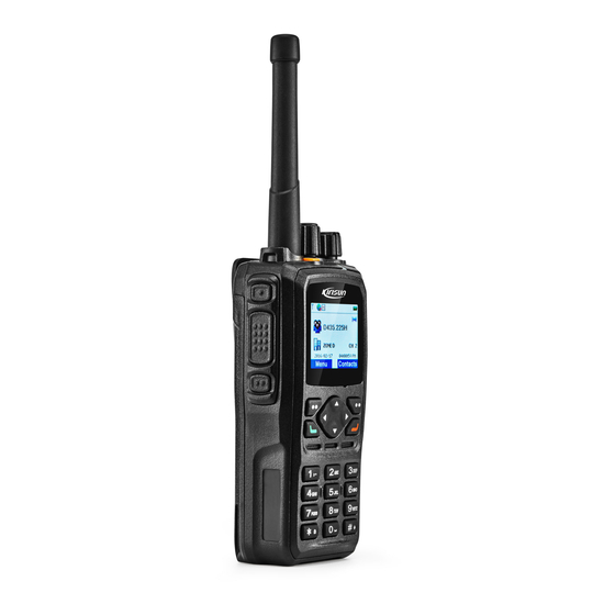
3 Introduction... - Page 15 Part Name Part Name Part Name Antenna Belt Clip Up Key Side Key 1 Digital Key LCD Display Screen PTT Key Battery Latch Comm Port Side Key 2 Battery LED Indicator Menu/OK Key Hang-up /Menu Key Power/Volume Knob Left Key Right Key Channel Selector Knob Dial Key...
-
Page 16: Basic Operation
Basic Operation Powering on/off To power on the radio, turn the power/volume knob clockwise until a click is heard; the LCD screen displays the power-on image and the backlight is on automatically; an alert tone and a sligt vibrating hint (created by motor)will sound and shake at the same time . - Page 17 4) Press【OK】 key to switch to the selected zone. 4.4 Selecting the Channel Turn the channel selector knob to select channel Each channel can be configured as analogue or digital. Turn the channel selector knob to switch between digital and analogue channel. When the channel is switched from digital to analogue, certain features are no longer available such as short message and etc.
- Page 18 7) Press to enter the menu item 8) Press to return to the last menu or the main interface. 9) Press to return to the main interface. Icon Signal strength More bars indicate stronger signal and less bars weak signal. It only show up when receiving.
- Page 19 Emergency Encryption Man Down Talkaround GPS is receiving GPS positioned Icon whirling indicates it is scanning The scan stays on priority channel 1 The scan stays on priority channel 2 IDType: Private call Group call All call Menu Selection: Selected Not selected...
-
Page 20: Initiating/Receiving A Call
LED Indication Red Indicator glows:the radio is transmitting. Green Indicator glows: the radio is receiving signals (speech message, text message and data) or it detected activity on the channel. Orange indicator glows: orange indicator glows during the call hang time in digital mode or auto reset time in analog mode. -
Page 21: Short Message
5.4 Receiving/Responding to a Call 1) LED indicator glows. 2) LCD displays icon of call type ( private call, group call, all call), alias or ID and incoming icon 3) Broadcasts received call. 4) You can press the PTT key during the call hang time to call the current contact. Note: For receiving call from group, the radio must be a member of the group (set by dealer with programming software). - Page 22 Enter text contents through keypad. Press to move the cursor to the right/left. Press【#】 key to switch typewriting and 【*】 key to switch to lower/upper case. In the non-digital input mode, press【1】 key to enter punctuation. Press the delete key to delete the character right before the cursor. 5) Press OK key after the message is edited and send, save or delete the message.
- Page 23 3) Select “template” and enter quick message list. 4) Select the target quick message in the list and press OK key to enter the editing interface. You can edit the quick message. 1) Press OK key to send, save or delete the edited message. 2) Select “Send”...
- Page 24 3) Select “Status Message” and enter status message list. 4) Select the target status message and press OK key to enter the interface of status message. 5) Press “Send” key and enter the “Contact” interface. 6) Select “Contact List” and press OK key to enter the contact list interface. 7) Select the target contact and press OK key to send the selected status message.
- Page 25 Deleting Short Message You can delete the message that is sent, received or saved. 6.5.1 Deleting the Message by Batch 1) Press to enter the menu. 2) Select and enter “ short message” menu. 3) Select “Delete Message” and enter the interface. 4) Select the mailbox of the message to be deleted (inbox, outbox or draft box) and press OK key to delete the message in the box.
-
Page 26: Emergency
7 Emergency During emergency, you can send a confirmed emergency alarm and an emergency voice message to the specified radio group. You can initiate an emergency alarm anytime even when it is receiving signals. The radio supports three kinds of emergency alarm mode. ... - Page 27 icon is and the outgoing call icon is 2) When the radio receives response, the LCD will show “Emergency Alarm Succeeded”. If the radio failed to receive response and when the retry count is used up, the LCD will show “Emergency Alarm Failed”。...
-
Page 28: Call Log
7.3 Exiting Emergency Alarm The radio will exit the alarm mode under the circumstances listed below: Receives emergency alarm response on Emergency alarm mode. The emergency alarm retry count is used up and no response is received. Press and hold the programmable button programmed as “Emergency Exit” 8 Call Log Through the call log, you can check and manage recent outgoing call, incoming calls and missed calls onthe radio. - Page 29 2) Select the target record which needs to be saved and you can press OK key to check, save or delete the target record. 3) Select “Save” and enter the interface for adding contact. 4) Enter the contact name. 5) Press Ok key to save the contact.. Deleting Call from the Call List 8.3.1 Deleting all the Records from the List.
-
Page 30: General Setting
9 General Setting Language Selection You can switch the radio languages. 1) Press in the home screen to enter the menu. 2) Select and enter “ setting” menu. 3) Select “Language Selection” and enter the interface. 4) Select the language and press OK key for switching to the language. Alert Tone Setting You can enable/disable the alert tone and adjusts the volume. - Page 31 “Information Alert Tone” – enables/disables the alert tone of receiving short message. “Finished Call Alert Tone” – enables/disables the alert tone of finished call. Press OK key and the LCD will show “Operation Succeeded” and save the alert tone. 9.2.2 Adjusting the Volume of Alert Tone 1) In the alert tone setting interface, select and enter the “Alert Tone Volume”...
- Page 32 4) Press OK key and the LCD will show “Operation Succeeded”. The vibration alert will be saved. Power Level Setting You can set high/low power for each channel. 1) Press in the home screen to enter the menu. Select and enter “ setting ”...
- Page 33 Press OK key and the LCD will show “Operation Succeeded”. The auto lock time is saved. During the set time, the keypad will be locked automatically if no operation is performed on it. 9.5.3 Locking the Keypad Quickly Press 【*】key in any interface to lock the keypad. 9.5.4 Unlocking the Keypad and then 【*】key to unlock the keypad.
- Page 34 4) Select the backlight duration for the screen. 5) Press OK key and the LCD will show “Operation Succeeded”. The time setting for turning off the screen will be saved. During the set time, the radio will turn off the screen if no operation is performed. Press any key to restore the brightness。...
- Page 35 9.10 Squelch Level Setting You can adjust the squelch level based on different situation to remove unnecessary calls in weak signals。 This setting is valid on analogue channel. 1) Press in the home screen to enter the menu. 2) Select and enter “ setting”...
-
Page 36: Advanced Features
10 Advanced Features 10.1 Radio Check Radio Check feature is used to check whether the target radio is activated in the system. The target user will automatically send a response to the caller radio without any audible or visual indication. 1) Press in the home screen to enter the menu. - Page 37 10.2 Call Alert Call Alert feature allows the caller radio to request the target radio to call back. 10.2.1 Receiving and Responding to Call Alert 1) When the radio received call alert, it will automatically reply if call alert decode is enabled. The LCD shows “Call Alert…”...
- Page 38 Note: If you press when sending “call alert”, the radio will exit the call alert mode. If the retry count is used up and no response is received, the radio will automatically stop sending call alert and display “Call Alert Failed” on the screen. 10.3 Radio Stun/Un-stun Stun/Un-stun feature allows the radio to stun/un-stun the target radio through air signaling.
- Page 39 3) Select “Stun/Un-stunned”. 4) Enter “Contact List” and select the target private call contact. The screen shows the alias or ID of the target radio and the radio indicates that it is sending stun/un-stun signaling. The red indicator glows. Waiting for response from the target radio.
- Page 40 Note: Once the radio is killed, the configuration data will be lost and the radio cannot go back to normal after reboot, so please operate with due care! The killed radio can only be revived by authorized dealer or supplier. 10.5 Remote Monitor Remote Monitor...
- Page 41 Note: If you press when the radio is sending remote monitor signaling, it will stop and exit the remote monitor mode. If the retry count is used up and no response is received, the radio automatically exits the mode and shows”Remote Control Failed”.
- Page 42 10.6.2 Editing the Scan List 1) Press in the home screen to enter the menu. 2) Select and enter “ Scan” menu. 3) Select “Editing Scan List”. You can operate as below on the scan list: Add: add the target channel to the scan list. Delete: delete the target channel from the scan list.
- Page 43 3) Wait for the alert tone of transmission permission to end and speak to the microphone. 4) Release PTT key to receive. 5) If you did not respond during the scan hang time,the radio will go on to scan other channels. 10.7 Man Down 1) Press...
- Page 44 2) Select and enter“ Application” menu. 3) Select “VOX” and enter “VOX” interface. 4) Select and enter “VOX Level” interface. 5) Press【Up】key or【Left】key to increase VOX level or【Down】key or【Right】key to decrease VOX level. 6) Press OK key and save the VOX level and return to the VOX setting interface. 10.9 If GPS is enabled, the radio will display the location information and offer location information to the software server (set by dealer through programming software).
- Page 45 4) Select and enter “GPS Switch” interface. 5) Select “On” or “Off” to enable/disable GPS. 10.9.3 Enabling/disabling GPS 1) Press in the home screen and enter the menu. 2) Select and enter “ Application” menu. 3) Select “GPS” and enter “GPS” interface. Select and enter “GPS Report On/Off”...
- Page 46 10.12 Bluetooth 1) Press in the home screen and enter the menu. 2) Select and enter “ Bluetooth” menu. 3) Select “Bluetooth Switch” and enter the interface. 4) Select “Enable Bluetooth” or “Disable Bluetooth” to enable/disable Bluetooth. 5) After the bluetooth is enabled, go back to the Bluetooth menu and select “Device Available”. 6)...
-
Page 47: Troubleshooting
11 Troubleshooting Troubleshooting Causes and Solutions A.Check if the battery is used up –charge the battery or change it if the power is out. B. Check if the power connecting pole is in proper contact with Failed to power on battery –try again after re-attachment. - Page 48 A. Poor antenna contact – fix the antenna. Failed receive B. Wrong RX/TX frequency – select the same TX/RX frequency. signals C. Beyond communication scope. The green indicator A. Check if the volume is at its lowest level – increase volume. glows but no sound B.
- Page 49 12 Major Technical Specification General Specification VHF: 136-174MHz, Frequency Range Channel Spacing 12.5kHz Weight 386 g (with battery and antenna) Size 135.8mm*63.5mm*39.1mm (height*width*thickness) Display 1.8 inches 65535 kind of color display Battery Capacity 7.4V 2000mAH lithium-ion battery Analogue: 12 hours Working Hour (5-5-90) Digital: 16 hours.
- Page 50 Work Environment Work Temperature -30℃~+60℃ Storage Temperature -40℃~+85℃ IP Rating IP67 Electrostatic Protection ±4kV (in contact) / ±8kV (air) Military Standard MIL-STD-810 C/D/E/F/G Damp proof MIL-STD-810 C/D/E/F/G Shock and Vibration MIL-STD-810 C/D/E/F/G...
- Page 51 Frequency Stability ±1.5ppm Analogue RX Sensitivity 0.3uV(12dB SNR)/0.22uV(12Db SNR, typical) Digital RX Sensitivity 0.3uV(5% bit error rate) Inter-modulation ETSI: 65dB TIA603: 70dB Adjacent Channel Selectivity ETSI/TIA603:60dB@12.5kHz Spurious Response ETSI/TIA603:70dB Suppression Conduction Spurious -57dBm Radiation Block ETSI:84dB TIA603:80dB Rated Audio Power 0.5W <3%...
- Page 52 Frequency Stability ±1.5ppm TX Power Low: 1W; High: 5W Voice and Noise -40dB@12.5kHz/-43dB Conduction Spurious -36dBm@<1GHz,-30dBm@>1GHz Radiation Adjacent Channel Power 60dB@12.5kHzz 5K19F3E@12.5kHz FM Modulation 12.5kHz(data only):5K39FXD 4FSK Modulation 12.5kHz(data + voice):5K39FXW Modulation Limit ±2.5kHz@12.5kHz Audio Response +1dB~-3dB 3% (Typical) Audio Distortion Vocoder AMBE++ Digital Protocol...
- Page 53 TTFF(cold start)initial positioning time <1 min TFF(hot start)initial positioning time <10 seconds Bluetooth Supported Type BT3.0HS+EDR Operation Frequency 2402MHz to 2480MHz GFSK, π/4QPSK, 8DPSK Modulation Channel number Channel separation 1MHz...
- Page 54 13 FCC Statement: This device complies with Part 15 of the FCC Rules. Operation is subject to the following two conditions: (1) This device may not cause harmful interference, and (2) this device must accept any interference received, including interference that may cause undesired operation.
- Page 55 -Connect the equipment into an outlet on a circuit different from that to which the receiver is connected. -Consult the dealer or an experienced radio/TV technician for help. NOTE 2: Any changes or modifications to this unit not expressly approved by the party responsible for compliance could void the user's authority to operate the equipment.
Need help?
Do you have a question about the DP99001 and is the answer not in the manual?
Questions and answers