Table of Contents
Advertisement
Quick Links
Advertisement
Table of Contents

Related Manuals for ATEQ ERD620


Summary of Contents for ATEQ ERD620
- Page 1 ATEQ ERD620 Quick Start Guide...
-
Page 2: Table Of Contents
Safety advisory / Warranty Good practices and safety instructions 2/48 Air quality requirements Preamble ATEQ ERD620, an universal valves tester Flow rate test Principe of a cycle Your ATEQ ERD620 Front panel Connectors on the back panel (with all options) - Page 3 ATEQ - Measurement Solution, Global Leader. 3/48 ATEQ 15, rue des Dames, Z.I. info@ateq.com T.: +33 1 30 80 1020 78340 LES CLAYES-SOUS-BOIS ateq.com F.: +33 1 30 54 1100 FRANCE ATEQ K.K. 3 – 41 ATEQ Building, Ikehata info@ateq.co.jp T.: +81 566-84-4670...
-
Page 4: Safety Advisory / Warranty
— Do not open a connected device. — Avoid splashing water on the device. ATEQ is at your disposal for any information concerning the use of the device under maximum safety conditions. We draw your attention to the fact that ATEQ cannot be held responsible for any accident related to a misuse of the measuring instrument, the workstation or non-compliance of the installation with safety rules. -
Page 5: Air Quality Requirements
For this purpose, we strongly recommend that a suitable airtight filter is installed between the part under test and the instrument. ATEQ recommends the following characteristics for the air supplied into the device. Air characteristics ISO standard 8573 class 0.1 μm and 0.1 mg/m... -
Page 6: Preamble
Preamble ATEQ ERD620, AN UNIVERSAL VALVES TESTER 6/48 ATEQ ERD620 is a pressure ramp generator with the options Contact event or Flow event. ATEQ ERD620 can memorize 128 different test programs. QSG_ERD620_421.00_EN_01 / 2020-09-09... -
Page 7: Flow Rate Test
As an option the flow event can be replaced by a dry contact event. 7/48 The ATEQ ERD620 can do direct or indirect measurements. In both cases, the flow meter can work in vacuum (optional). Measurement principle When the fluid (gas) enters the device 1, it moves through a calibrated flow tube 2 which causes a drop in pressure. -
Page 8: Principe Of A Cycle
Indirect measurement The indirect measurement (also called recovery mode or under bell) allows a considerable gain in time as the flow which enters into the device is already stabilized. The test pressure is first applied to the input of the part under test 1 and then to the device 2. -
Page 9: Your Ateq Erd620
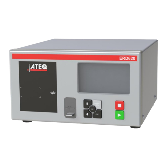
Your ATEQ ERD620 FRONT PANEL The user interface is located on the front panel. 9/48 Display Cycle keys Navigation keys USB connectors For more information, refer to User interface. QSG_ERD620_421.00_EN_01 / 2020-09-09... -
Page 10: Connectors On The Back Panel (With All Options)
CONNECTORS ON THE BACK PANEL (WITH ALL OPTIONS) 10/48 QSG_ERD620_421.00_EN_01 / 2020-09-09... - Page 11 Output to be left to the atmosphere A automatic connector option Output to be left to the atmosphere Air supply energy information ATEQ Part number / Serial number External capillary connector (option) Ground Relay board connector (digital inputs/outputs and 24 V DC - 2 A...
-
Page 12: Power Supply Connectors
POWER SUPPLY CONNECTORS The device can be connected to an external power supply (24 V DC - 2 A) or provided with an internal power supply (100 / 240 V AC) (option). External supply 12/48 24 V DC connector (J7) The device can be connected to a 24 V DC - 2 A power supply through a M12 4 pins type connector. -
Page 13: Digital Links
Internal supply only 100 / 240 V AC connector (J7) The device can be connected to a 100 / 240 V AC power supply. 13/48 This connector has an ON/OFF button. It is mandatory to connect the device to the ground with a good link to the ground, to protect against electric hazard or electrocution. - Page 14 Profibus (option) (J12) or Printer RS232 connector / Modbus (option) Profibus SubD 9 pins female connector option 14/48 Profibus: SubD 9 pins female connector. Pin number Signal PE (ground) Not used Data line A CNTR - A (repeater control signal) DGND (logic ground) VP (supply) Not used...
- Page 15 Examples of frames outputs Pressure up + Step Flow + Pressure Down 9 10 11 12 13 14 15 16 17 18 19 20 21 22 23 24 25 26 27 28 29 30 31 32 33 34 35 36 37 38 39 40 <...
- Page 16 Pressure up + Step Flow 9 10 11 12 13 14 15 16 17 18 19 20 21 22 23 24 25 26 27 28 29 30 31 32 33 34 35 36 37 38 39 40 < 0 1 > : A B C D E F G H I J <...
- Page 17 Step Flow + Pressure down 9 10 11 12 13 14 15 16 17 18 19 20 21 22 23 24 25 26 27 28 29 30 31 32 33 34 35 36 37 38 39 40 < 0 1 > : A B C D E F G H I J <...
- Page 18 Pressure up 9 10 11 12 13 14 15 16 17 18 19 20 21 22 23 24 25 26 27 28 29 30 31 32 33 34 35 36 37 38 39 40 < 0 1 > : A B C D E F G H I J <...
- Page 19 Up + down contact 9 10 11 12 13 14 15 16 17 18 19 20 21 22 23 24 25 26 27 28 29 30 31 32 33 34 35 36 37 38 39 40 < 0 3 > : A B C D E F G H I J <...
- Page 20 Up contact 9 10 11 12 13 14 15 16 17 18 19 20 21 22 23 24 25 26 27 28 29 30 31 32 33 34 35 36 37 38 39 40 < 0 3 > : A B C D E F G H I J K L <...
- Page 21 Examples of frames exports 21/48 QSG_ERD620_421.00_EN_01 / 2020-09-09...
- Page 22 22/48 QSG_ERD620_421.00_EN_01 / 2020-09-09...
- Page 23 Devicenet connectors (J5) (J6) (option) M12 type connector - 5 pins male connector (J5) (Devicenet input) For connection to others ATEQ devices. 23/48 Pin number Signal Drain CAN_H CAN_L M12 type connector - 5 pins female connector (J6) (Devicenet output) For connection to other ATEQ devices.
- Page 24 Profinet connectors (J5 + J6) (option) M12 D coded type connector - 4 pins female connector (J5 + J6) Pin number Signal 24/48 Ethernet Tx + (Transmit Data +) Ethernet Rx + (Receive Data +) Ethernet Tx - (Transmit Data -) Ethernet Rx - (Receive Data -) Ethernet connector (J5 + J6) (option) Standard connection Ethernet TCP / IP protocol.
-
Page 25: Digital Inputs/Outputs
DIGITAL INPUTS/OUTPUTS The 24V DC power supply for the digital inputs can be provided by 2 means: — The internal power supply of the device (0.3 A max) — An external power supply provided by the customer. Inputs default mode is PNP. NPN mode is available on request. 25/48 Relay board connector (J11) (option) Characteristics... - Page 26 Program selection extension connector (J10) (option) The J10 connector is an extension of the J11 connector that enables the selection of 128 programs. Characteristics 26/48 — Inputs • Activation: + 24 V DC Pin number Inputs/outputs Description 1 (I8) Input 8 Program selection from 33 to 64 (programmable input) 2 (I9) Input 9...
- Page 27 Valve codes and auxiliary outputs board connector (J9) (option) Characteristics — Outputs: 27/48 • 24 V DC - 100 mA max per output — Inputs: • Activation: + 24 V DC. Pin number Inputs / outputs Description + 24 V DC Common (outputs 1, 2,3) Output 1 Open collector...
- Page 28 Analog outputs connector (J1) (option) M12 – 8 pin Female connector 28/48 Pin number Description Pressure analog output (ground) Pressure analog output (0-10VDC) Flow analog output (ground) Flow analog output (0-10VDC) Dry contact input (signal side) Dry contact input (ground side) Not connected Not connected For the contact event option, a dry contact (no voltage) must be used to the pin 5 and pin 6...
-
Page 29: Pneumatic Connectors
Pneumatic supply 29/48 The pneumatic supply has to meet specific requirements recommended by ATEQ. Refer to Good practices and safety instructions section. A specific filter may be necessary. The air is supplied via the filter located on the back panel of the device. - Page 30 Pneumatic outputs 0.6 MPa A and B: automatic connectors option. These connectors are used to drive pneumatic caps on the part under test. 30/48 External capillary connectors M1 and M2 connectors are pneumatic inputs used for external capillary connection (option). External pressure monitoring connector The P connector is a pneumatic input...
- Page 31 Temperature probe connector The J13 connector is used for tests with external capillary option. 31/48 Air supply input for options Instant fitting: 6 mm diameter — 0.6 MPa air supply input for internal valves for 1 MPa range — Vacuum input for vacuum range Metallic fitting: 4/6 mm diameter —...
- Page 32 Capillary output connector This connector needs to be open to atmosphere for indirect mode. Instant fitting: 8, 10 or 12 mm diameter. 32/48 ATM 4 mm connector This connector needs to be open to atmosphere. Instant fitting: 4 mm diameter. ATM 6 mm connector This connector needs to be open to atmosphere.
-
Page 33: Pneumatics Configuration
PNEUMATICS CONFIGURATION According to the part under test and the pressure range, different configurations can be used. M1 and M2 connectors are always fitted with caps except for external capillary option. 33/48 Direct mode - Internal back pressure - until 0.5 MPa This configuration is used for direct mode at medium pressure range. - Page 34 Direct mode - 1 MPa range This configuration is used for direct mode at high pressure range. 34/48 Connection Option / description Air supply to 1 Connection of the regulator air supply to the filter input (1.2 MPa) Air supply to 4 Connection of the air supply to the valve pilot input (0.6 MPa) 2 to 3 Connection of the test output to the part under test (direct mode option)
- Page 35 Indirect mode - 1 MPa range This configuration is used for indirect mode at high pressure range. 35/48 Connection Option / description Air supply to 1 Connection of the regulator air supply to the filter input (1.2 MPa) 4 to 3 Connection of the regulator output to the part under test 3 to 2 Connection of the part to the test input (indirect mode option)
-
Page 36: User Interface
User interface OVERVIEW The user interface comprises a display and user keys located on the front panel. 36/48 1 Display 2 Cycle keys 3 Navigation keys KEYS Cycle keys The cycle keys are used to start and to stop a measurement cycle. Name Function On the Program screen, starts a measurement cycle and opens the... -
Page 37: Display
Navigation keys The navigation keys are used to select menus/options and change parameter values. Name Function Up key Scrolls up or increases numerical values. 37/48 Down key Scrolls down or decreases numerical values. Returns to the MAIN MENU screen or opens menus and options, validates parameters. - Page 38 The Measurement cycle screen The Measurement cycle screen displays the different values of the current test (or last one). Test pressure measurement Program name 38/48 Test result or step phase Flow reject value Vertical line test result* Step flow measurement (when the function Step flow is selected) Remaining time of the current phase...
-
Page 39: Starting Up
Starting up POWER UP 1. Make sure that all the necessary connections are in 39/48 place. Electrical: such as power supply, inputs/outputs Pneumatic: including line pressure supply. 2. Power up your device When power-up is completed, the Program screen is displayed, with last program used on screen. PREPARING A PROGRAM Use this procedure to configure a new test program. -
Page 40: Modifying A Parameter
CONFIGURING THE ASSOCIATED MEASUREMENTS 3. Select the program to configure and press The parameters of the selected measurement type are displayed. 4. Define the measurement cycle parameters. 40/48 See: Modifying a parameter. MODIFYING A PARAMETER Use this procedure to complete the test program setup. The protection of the parameters is configurable. -
Page 41: Selecting A Program
SELECTING A PROGRAM OR A SEQUENCE If necessary, you can select another program or another sequence if sequence mode is activated in the configuration. 1. Press up/down 41/48 STARTING AND STOPPING CURRENT CYCLE Use the front panel keys to start/stop a measurement cycle. With the desired program displayed on the Program screen: STARTING A MEASUREMENT CYCLE 1. Press Start... -
Page 42: User Adjustments
User adjustments OPTIONS OF THE MENUS 42/48 Different menus are accessible on the MAIN MENU screen. For more information, refer to the Reference Manual. SPECIAL CYCLE MENU menu Use this menu to carry out specific procedures necessary to ensure the proper operation of measurement cycles (for example, adjustment of pressure regulator). - Page 43 Default parameters of the FLOW type tests Label Parameter Description Coupling time COUPL. A or COUPL. B Required times when instrument manage automatic jigs (COUPL. A can be used as a waiting time before generating pressure) Pressure up time Time for the rising ramp P.
- Page 44 Additional functions Label Function Description Auxiliaries output 24 V Available outputs for external automatism 24V OUTPUTS Analog output Duplicate the flow and pressure measurements on ANALOG OUTPUT the analogues outputs (Window mode is only for 44/48 Direct or Indirect Flow Test and do not use with ERD) Automatic connector Function to manage automatic jigs...
- Page 45 CONFIGURATION menu Use this menu to configure your ATEQ device. 45/48 Label Function Description Language Selection of the language displayed on the screen LANGUAGE Pneumatics Configuration of the pneumatics functions of the device PNEUMATIC > READY STATUS Out of cycle electronic regulator instruction choice...
- Page 46 Statistics for each program USB : the results will be saved at the same time on the internal memory and on the USB stick (Format Fat32) > ATEQ > RESULTS >Serial Number > .csv file by date (YYYYMMDD.csv). QSG_ERD620_421.00_EN_01 / 2020-09-09...
- Page 47 USB menu This section describes save and restore parameters on an external USB stick (format Fat32). 47/48 Label Description Save parameters Save parameters on an external USB memory device for restoring later Restore parameters Restore parameters from an external USB memory device QSG_ERD620_421.00_EN_01 / 2020-09-09...
-
Page 48: Specifications
Specifications CHARACTERISTICS Technical characteristics of the device. 48/48 Main characteristics: Characteristics Values Case dimensions: Height x Width x Depth 150 x 250 x 270 mm Overall dimensions 150 x 250 x 360 mm Mass About 8 kg (17.6 lbs) Electrical power supply —...
Need help?
Do you have a question about the ERD620 and is the answer not in the manual?
Questions and answers