
Related Manuals for ATEQ LRT 6000


Summary of Contents for ATEQ LRT 6000
- Page 1 USER MANUAL ATEQ LRT 6000 LOOP TESTER Version 4 Reference manual: UM-31400E-U / Product: EZ-157B...
- Page 3 REVISIONS OF THE ATEQ LRT6000 USER MANUAL Due to continuing improvements, the information contained in this user manual, the features and design of this device are subject to be changed without prior notice. Date Edition/Revision Reference Chapters up dating Week/Year...
- Page 5 ». standard EN 55 022 « Information technology equipment - limits and methods of measurements », This enables ATEQ to guarantee that this instrument may be used in complete safety under the following environmental conditions : ...
- Page 7 ATEQ is at your disposal for any further information concerning the use of the instrument under maximum safety conditions. We would like to bring to your attention that ATEQ will not be held...
- Page 9 ATEQ is attached to the COFRAC and delivers a certificate following a calibration. TRAINING COURSES In the framework of partnership with our customers, ATEQ offers two types of training in order to optimise the usage and knowledge of our instruments. They are aimed at different levels of technician: •...
- Page 11 PREFACE Dear Customer, You have just purchased an ATEQ instrument, we thank you for the trust you have placed on our brand. This instrument has been designed to ensure a long and unparalleled life expectancy, and we are convinced that it will give you complete satisfaction during many long years of operation.
-
Page 13: Table Of Contents
Table of contents TABLE OF CONTENTS Preamble MEASUREMENT PRINCIPLE 1. DEFINITION AND PRINCIPLEOF THE ATEQ LRT6000 ..............3 1.1. Loop tester ........................... 3 1.2. Micro Ohmmeter high current test (HCLF) ................... 3 2. MEASUREMENT RANGE ........................4... - Page 14 2. SERVICE ............................53 Appendices ATEQ LRT6000 1. TECHNICALS CHARACTERISTICS ....................55 2. DIMENSION DRAWING ........................55 3. SAFETY INFORMATION / WARNING ....................56 4. RECYCLING ............................58 Index UM-31400E-U User manual LRT 6000 Page 2 / 60...
-
Page 15: Preamble
Preamble Preamble MEASUREMENT PRINCIPLE 1. DEFINITION AND PRINCIPLEOF THE ATEQ LRT6000 The ATEQ LRT6000 is a multifunction device which tests the resistive continuity. 1.1. L OOP TESTER The measurement principle is to generate an alternative current TOOL (10 A) in a loop through a plier and make impedance measurements of this loop. -
Page 16: Measurement Range
<100 A : 0.1. >100 A : 1. 100 Hz Frequency F 1% MV 200 Hz MV = Measured Value. * Depends of the injected current and the injection clamp size. UM-31400E-U User manual LRT 6000 Page 4 / 60... -
Page 17: Chapter 1 Instrument Installation
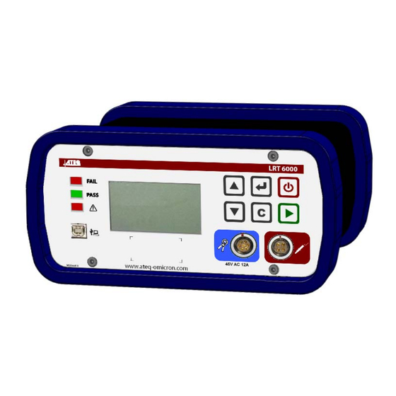
Chapter 1 INSTRUMENT INSTALLATION 1. APPEARANCE The ATEQ LRT6000 case is made with two anodized aluminum parts assuring durability and lightness. The case is surrounded by two rubbers to protects the device from falls and avoid marking the shocked part. -
Page 18: Instrument Installation
To remove the battery from the device, pull slowly the two captives clips to unlock (1) then remove the battery pack (2). Reinstall the battery by doing same operations reversal way. UM-31400E-U User manual LRT 6000 Page 6 / 60... -
Page 19: Front Face Electrics Connectors
Results recovery for archiving and statistic analysis with spreadsheet software's. See the Winateq300 software manual. 2.4. R EAR SIDE ELECTRIC CONNECTOR 2.4.1. Remote control connector 4 pins connector to plug a remote control (TLC6000 model). UM-31400E-U User manual LRT 6000 Page 7 / 60... -
Page 20: Injection Clamp
15 mΩ 3 mΩ 2 mΩ 1 mΩ Z (200 Hz) 7 mΩ 2 mΩ 1 mΩ 0.3 mΩ Z (200 Hz) Do not open the clamp during a measurement cycle. UM-31400E-U User manual LRT 6000 Page 8 / 60... -
Page 21: Chapter 2 User Interfaces
Chapter 2 – User interfaces Chapter 2 USER INTERFACES 1. PRESENTATION Results lights Control keys connector Tests connectors Navigation and control keys Display UM-31400E-U User manual LRT 6000 Page 9 / 60... -
Page 22: Keyboard Presentation
Move up or increase the numeric values. Move down or decrease the numeric values. Enter in the menu or parameters and validation. Return to the previous function or menu. Escape without parameter's modification. UM-31400E-U User manual LRT 6000 Page 10 / 60... -
Page 23: Lcd Display
Max Resistance measured in the 0.51 allowed loop 4. FUNCTIONS OF THE INDICATOR LIGHTS symbol represents an indicator which is lit. Measurement in Pass part light. Fail part light. Alarm. process. UM-31400E-U User manual LRT 6000 Page 11 / 60... -
Page 24: Battery Level
Note: if the instrument doesn't turn on, before any service in the device, charge completely the battery or replace it with a full one. Important note: See the battery instructions in appendices. UM-31400E-U User manual LRT 6000 Page 12 / 60... -
Page 25: Chapter 3 Starting Up And Adjustments
Manual mode: Test selection Z Max R Max 10.0m 10.0m HCLF 200Hz Expert Expert mode: Test selection Z Max R Max 10.0m 10.0m "Plane A" Sequence mode: Start Seq. +/- User manual LRT 6000 Page 13 / 60 UM-31400E-U... -
Page 26: Measurements Modes
1.2. S ERVICE MODE One service mode is available: Service mode: the user has access to some parameters and can reset the device to the factory settings (complete reset). User manual LRT 6000 Page 14 / 60 UM-31400E-U... -
Page 27: Selection Of The Measurement Type
1) Beginning of the test time. 4. TEST STOP The measure stops: When the measure is "Pass", the result is displayed. Automatically at the end of the test time. User manual LRT 6000 Page 15 / 60 UM-31400E-U... -
Page 28: Parameters Adjust
CR Min : 0.0μ to the left hand of the display. PARAMETERS Current : 10A Adjust the others parameters by using the same process. >CR Max : 90.0μ CR Min : 0.0μ User manual LRT 6000 Page 16 / 60 UM-31400E-U... -
Page 29: Parameters To Adjust
Unit = µOhm. "CR1 Max" Multiple This parameter defined the number of Test: measurements carry on by the user. 1 - 2 - 3 - 4 User manual LRT 6000 Page 17 / 60 UM-31400E-U... - Page 30 Name3A > Name3A 3B 3C 3D: characters Name3D maximum, define Contact resistance (Rc). 2B, 2C, 2D, 3B, 3C and 3D appear in function of the "Multitest" parameter. User manual LRT 6000 Page 18 / 60 UM-31400E-U...
- Page 31 Unit = mOhm. "RLoop Max" This is to select the frequency of the Frequency alternative current injected in the loop. Values to adjust: 100Hz or 200Hz (expert "Frequency" mode only). User manual LRT 6000 Page 19 / 60 UM-31400E-U...
-
Page 32: Micro Ohmmeter High Current "Hclf
Z (m ) R (m ) The user can apply the probes during this time 0.681 0. 657 (the measure will begin at the end of this time). Injection time (configured) User manual LRT 6000 Page 20 / 60 UM-31400E-U... - Page 33 If the status is not "TO DO" then the measurement is reset by changing the status in Valid "TO DO". Precedent If the status is "TO DO", it changing the status to N/A. User manual LRT 6000 Page 21 / 60 UM-31400E-U...
-
Page 34: Loop Tester
10.1A 0.07m The test stops and the measurements values are displayed. R Max PASS 0.51 Note: if the device detects a fail part or an alarm, a discontinued beep is triggered. User manual LRT 6000 Page 22 / 60 UM-31400E-U... -
Page 35: Passwords
HCLF 100Hz Expert The device will enter into the selected mode. If the password is fail, the message "Password error" is displayed. Test Selection Z Max R Max 10.0m 10.0m User manual LRT 6000 Page 23 / 60 UM-31400E-U... -
Page 36: Sequences Configuration (Winateq300/Ax)
INDOW DETAILS Name of the device connected (left up) and number of the selected program or its name if existing. Display window of the programs list. Display window of the selected sequence. User manual LRT 6000 Page 24 / 60 UM-31400E-U... -
Page 37: Available Commands Detail
(right) at the position you want. Second solution: select a program, do a "right click", the menu appears asking insertion position in the sequence (Insert before or Insert after). User manual LRT 6000 Page 25 / 60 UM-31400E-U... - Page 38 Once the sequence is created, it must download it into the device, use the "Save Sequence" key. To completely delete the sequence, press the "Reset Sequence" key, the device will prompt you a confirmation. User manual LRT 6000 Page 26 / 60 UM-31400E-U...
-
Page 39: Sequence Mode Running
>Name : JACK Then select "Validation" and press the key to validate. Validation Note: this name will appear in the results. User manual LRT 6000 Page 27 / 60 UM-31400E-U... - Page 40 Jump to the following step by pressing the key. 200Hz Note: if the option "Sequence PP" is validated the steps will Z Max HCLF R Max TO DO 10.0m 10.0m chain automatically if the current step is pass. User manual LRT 6000 Page 28 / 60 UM-31400E-U...
- Page 41 Prog1 200Hz That the measurement is PASS, FAIL or N/A, it can be 2:N/A change in "TO DO" by pressing the TO DO Change key. Z Max CR1 Max 10.0m 50μ User manual LRT 6000 Page 29 / 60 UM-31400E-U...
- Page 42 It is possible to do again a step already measured., In tis case, 1:2.0μ 2:N/A the CR "PASS" and "N/A" are memorized , the others gets the 4:1.2μ "TO DO" status. HCLF Z (m ) R (m ) TO DO 0.681 0. 657 User manual LRT 6000 Page 30 / 60 UM-31400E-U...
-
Page 43: Validate And Complete The Séquence
The validation menu is displayed, press on the key to C on fi rm confirm. Re tu rn When this message appears, the sequence is saved. The SEQUENCE SAVED steps no carried on didn't appear in the results. User manual LRT 6000 Page 31 / 60 UM-31400E-U... - Page 44 "Seq. cancellation" menu and press the key. >Seq. cancellation CANCELLATION SEQUENCE The cancellation menu is displayed, press on Confirm confirm. Abort When this message appears the sequence is cancelled. SEQUENCE CANCELED User manual LRT 6000 Page 32 / 60 UM-31400E-U...
-
Page 45: Displaying The Sequences Filters
Tests –CANCEL-: all the steps which are >1:Pr01 be cancelled in the sequence to ease these steps to retrieve. Tests -N/A- Tests -N/A- : all the steps which are be >1:Pr01 reported "Not applicable". User manual LRT 6000 Page 33 / 60 UM-31400E-U... -
Page 46: Program Mode
CR1 Max instructions displayed by the device. 50μ Prog1 200Hz 1:2.0μ 2:4.7μ When the program is finished, the measurements results are displayed. PASS Z (m ) R (m ) 0.681 0. 657 User manual LRT 6000 Page 34 / 60 UM-31400E-U... -
Page 47: Functions Of The Instrument
Impedance (ZLoop Max) Maximum Loop > 0 to 20 mΩ (10) resistance (RLoop Max) > 1 – 2 – 3 – 4 (1) Multiple test > Manual / Auto (Yes) Validation UM-31400E-U User manual LRT 6000 Page 35 / 60... - Page 48 Name3A Name3B / Appears from Multiple test 2 > 20 characters max. Name3C/Name3D (3B) / 3 (3C) / 4 (3D) Password: Service mode Code: XXXX/Validate > 1W to 40W Max power UM-31400E-U User manual LRT 6000 Page 36 / 60...
-
Page 49: Generals Parameters
> Yes / No (No) > Yes / No (No) > Yes / No (No) > Yes / No (Yes) > Yes / No (No) 100A > Yes / No (No) UM-31400E-U User manual LRT 6000 Page 37 / 60... - Page 50 Day / Month / Year Date > Hour / Minutes Hour > Calibration > DD/MM/YY > 11 characters maximum CLP1 > CPL2 > CLP3 S/N Clamps > CLP1 > CPL2 > CLP3 Erase clamp > UM-31400E-U User manual LRT 6000 Page 38 / 60...
-
Page 51: System Settings
Hour : 10:25 LANGUAGE LIST By using the keys, select the language. Francais >English Validate with the key to confirm the new displayed Deutsch language. UM-31400E-U User manual LRT 6000 Page 39 / 60... -
Page 52: System Settings Menu
Hour : 10:25 from 1 (black screen) to 70 (white screen) by step of 10 % then Backlight : 60% Contrast : 60 < validate with the Key. UM-31400E-U User manual LRT 6000 Page 40 / 60... -
Page 53: Manual Settings
MANUAL SETTINGS MANUAL SETTINGS >Inject. Time : 1s Then all the parameters for the manual measurements are Test time : 300s displayed, that they can be modified. : On UM-31400E-U User manual LRT 6000 Page 41 / 60... -
Page 54: Accessible Parameters In Service Mode
10/08/09 Hour : 10:25 Backlight : 60% keys, adjust the year. SYSTEM SETTINGS MENU >Date : 10/08/09 To save the date, validate with the key. Hour : 10:25 Backlight : 60% UM-31400E-U User manual LRT 6000 Page 42 / 60... - Page 55 To save the date, validate with the key. Hour : 10:25 >Cal. : 25/07/15 OUTDATED CALIBRATION When the calibration date has passed, the following message DATE appears when the device is powered on. Confirm UM-31400E-U User manual LRT 6000 Page 43 / 60...
- Page 56 (2567). CLAMP SERVICE Remove the clamp Press the key to continue, to carry on the learning cycle From the loop and please follow the instructions displayed. Continue Cancel UM-31400E-U User manual LRT 6000 Page 44 / 60...
-
Page 57: Factory Reset
FACTORY RESET The device prompts you to confirm the reseting. Confirm with Confirm key or abort with the key. Abort The confirmation message is displayed. PLEASE WAIT FACTORY RESET UM-31400E-U User manual LRT 6000 Page 45 / 60... -
Page 58: Passwords Reminder
Service Mode: a password is requested; this password is fixed and cannot be modified, value: 7287. Clamp service: a password is requested; this password is fixed and cannot be modified, value: 2567. UM-31400E-U User manual LRT 6000 Page 46 / 60... -
Page 59: Chapter 5 Accessories
Chapter 5 ACCESSORIES 1. ACCESSORIES FITTED 1.1. P OWER SUPPLY The LRT 6000 is fitted with a battery pack. This pack must be charge with the power supply fitted, connect the charger on the electric network from 100 to 245V AC;... -
Page 60: Clamp And Probes
1 measurement device LRT6000, 1 second battery, 1 power supply for battery charging, 1 Clamp small model (CLP1), 1 Clamp large model (CLP2), 2 probes, 1 test loop. UM-31400E-U User manual LRT 6000 Page 48 / 60... -
Page 61: Optional Accessories
This remote control replicates the device front face to drive it easily on a remote area. 2.2. S OFT CARRYING CASE The soft carrying case allows the user to carry easier the device on the test area. UM-31400E-U User manual LRT 6000 Page 49 / 60... - Page 62 Chapter 5 - Accessories UM-31400E-U User manual LRT 6000 Page 50 / 60...
-
Page 63: Chapter 6 Error Messages
Chapter 6 –Error messages Chapter 6 ERROR MESSAGES The ATEQ LRT6000 can display error messages if there are operational problems. PROBLEM LIGHTS DISPLAYED MESSAGES HCLF probes The HCLF probes are not plugged. not connected Action: the probes must be plugged on the device for carrying out tests measurements. -
Page 64: Configuration Error
PARAMETERS not compatible. ERROR Action: try to make a reset of the system and restart the instrument, if the problem persists, contact ATEQ after sales services. UM-31400E-U User manual LRT 6000 Page 52 / 60... -
Page 65: Probable Failures
3) Clean carefully with a soft cloth the clamp contacts. 4) Contact the ATEQ after sales service. The ATEQ Company disclaims any responsibility if the instruments calibration and adjustment would not be performed by its services. 2. SERVICE Please refer to the LRT6000 service manual. - Page 66 Chapter 7 – Failures and Service UM-31400E-U User manual LRT 6000 Page 54 / 60...
-
Page 67: Appendices Ateq Lrt6000
-20° C to +70° C (-4° F to +158° F) Recommendations for the Storage and transportation: see the battery: instructions hereafter. 2. DIMENSION DRAWING L: 240 mm / H: 120 mm / D: 210 mm. UM-31400E-U User manual LRT 6000 Page 55 / 60... -
Page 68: Safety Information / Warning
Use a specified charger approved by the ATEQ manufacturer and supplied with the device. Safety for Lithium Polymer battery use The battery must imperatively be placed on a non-flammable surface during charging (ceramic platter or metal box). - Page 69 The ATEQ Company couldn't control the proper use of the battery for each customer (charge, discharge, storage etc.), It can not be held responsible for damage to persons and property.
-
Page 70: Recycling
This applies to your tool but also to any enhancements marked with this symbol. Do not dispose of these products as unsorted municipal waste. For further information, please contact ATEQ. UM-31400E-U User manual LRT 6000 Page 58 / 60... -
Page 71: Index
Service ..........53 Hour ............ 43 Soft carrying case ....... 49 Start cycle ........... 15 I key ............ 10 Status management ......29 Injection time ........17 Stop cycle ........15, 22 UM-31400E-U User manual LRT 6000 Page 59 / 60... - Page 72 Tests – TO DO - ......... 33 Tests Connectors ......... 7 What to do in case of failure? ..... 53 Tests -N/A- ......... 33 Transport case ........48 Zloop Max ........17, 19 UM-31400E-U User manual LRT 6000 Page 60 / 60...
- Page 74 This document is the exclusive property of ATEQ. It may not be communicated, reproduced or used without prior consent.
Need help?
Do you have a question about the LRT 6000 and is the answer not in the manual?
Questions and answers