Table of Contents
Advertisement
Quick Links
RDF880KN.. with temperature display
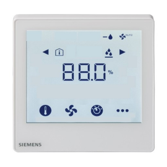
RDF880KN.. with % r.h. display
Touch Screen Flush-mount Room Thermostats
with KNX Communications
RDF880KN..
Under Floor Heating (UFH) control application
with an additional HMI for Variable Refrigerant Flow (VRF) commands via KNX S-Mode
Basic documentation
A6V12318532_en--_a
Smart Infrastructure
2021-03-22
Advertisement
Table of Contents

Related Manuals for Siemens RDF880KN Series


Summary of Contents for Siemens RDF880KN Series
- Page 1 RDF880KN.. with temperature display RDF880KN.. with % r.h. display Touch Screen Flush-mount Room Thermostats with KNX Communications RDF880KN.. Under Floor Heating (UFH) control application with an additional HMI for Variable Refrigerant Flow (VRF) commands via KNX S-Mode Basic documentation A6V12318532_en--_a Smart Infrastructure 2021-03-22...
-
Page 2: Table Of Contents
Setting parameters using the local HMI ..........39 3.13.2 Setting and downloading parameters using the tools ......40 3.13.3 Service level parameters ................. 41 3.13.4 Expert level parameters with diagnostics and test ........42 2 / 60 Siemens RDF880KN.. Basic documentation A6V12318532_en--_a Smart Infrastructure Contents 2021-03-22... - Page 3 Parameter settings in ETS ..............50 Connection .................... 51 Connection terminals ................51 Connection diagrams ................52 Mechanical design ................53 General ....................53 Dimensions ..................... 54 Technical data ..................57 3 / 60 Siemens RDF880KN.. Basic documentation A6V12318532_en--_a Smart Infrastructure Table of contents 2021-03-22...
-
Page 4: About This Document
(EN: https://my.knx.org/shop/product?language=en&product_type_category=book s&product_type=handbook https://my.knx.org/shop/product?language=de&product_type_category=book s&product_type=handbook) Synco and KNX (see CE1N3127 KNX bus, Data Sheet www.siemens.com/synco) CE1P3127 Communication via the KNX bus for Synco 700, 900 and RXB/RXL, Basic Documentation XLS template in Planning and commissioning protocol, communication Synco 700 CE1N3121... -
Page 5: Before You Start
Before you start 1.3.1 Copyright This document may be duplicated and distributed only with the express permission of Siemens, and may be passed only to authorized persons or companies with the required technical knowledge. 1.3.2 Quality assurance This document was prepared with great care. -
Page 6: Target Audience, Prerequisites
They are called communication objects (CO). The communication objects of the RDF880KN… room thermostats work in S-Mode mainly. These objects are described accordingly. A list of the parameters is shown in section 3.13. 6 / 60 Siemens RDF880KN.. Basic documentation A6V12318532_en--_a Smart Infrastructure 2021-03-22... -
Page 7: Summary
VRF HMI Room unit to send commands to a VRF indoor unit via a KNX/VRF • gateway Under Floor Heating unit with a VRF HMI function • Download via ETS (All in OFF positions) UFH only VRF HMI only VRF HMI and UFH 7 / 60 Siemens RDF880KN.. Basic documentation A6V12318532_en--_a Smart Infrastructure 2021-03-22... - Page 8 60.3 mm fixing centers, minimum 40 mm suitable conduit boxes depth • RDF880KN/NF: Recessed square conduit boxes with 60.3 mm fixing centers, minimum 40 mm depth 8 / 60 Siemens RDF880KN.. Basic documentation A6V12318532_en--_a Smart Infrastructure 2021-03-22...
-
Page 9: User Interface
/ icon to select different alarms for viewing. to select programming mode (KNX). Touch for 5 seconds to select parameter mode (Service/Expert level). Touch for 5 seconds 9 / 60 Siemens RDF880KN.. Basic documentation A6V12318532_en--_a Smart Infrastructure 2021-03-22... -
Page 10: Integration With Knx Bus
• local DIP switches/HMI • ETS Desigo and third-party The KNX communicating devices can be integrated into the Siemens building systems automation and control systems (BACS) Desigo or third-party systems. For integration, you can use either S-Mode (group addressing) or individual addressing. -
Page 11: Equipment Combinations
QAP1030/UFH has a special head and 4 m long that is more suitable for such application. Refer to data sheets of the actuators for the maximum number of parallel operation. 11 / 60 Siemens RDF880KN.. Basic documentation A6V12318532_en--_a Smart Infrastructure... -
Page 12: Accessories
Product no. / SSN Data sheet Single mounting frame , Ivory White ARG800.1 / S55770-T370 KNX Power supply 160 mA (Siemens BT LV) 5WG1 125-1AB02 KNX Power supply 320 mA (Siemens BT LV) 5WG1 125-1AB12 KNX Power supply 640 mA (Siemens BT LV) 5WG1 125-1AB22 See the dimensions of mounting frame on page 56. -
Page 13: Functions
The temperature value is a display-only information. Outdoor temperature using the bus In S-Mode, the corresponding communication object needs to be bound with a KNX sensor device for obtaining outdoor temperature. 13 / 60 Siemens RDF880KN.. Basic documentation A6V12318532_en--_a Smart Infrastructure 2021-03-22... -
Page 14: Operating Modes
VRF operating mode. Use +/– to change the VRF operating mode. If P02 = 2, the following operating mode for UFH can be selected via or : Comfort (ON), Economy (ECO) 14 / 60 Siemens RDF880KN.. Basic documentation A6V12318532_en--_a Smart Infrastructure 2021-03-22... - Page 15 • In Protection mode, both the icons do not display since both setpoint and fan speed are not adjustable. 15 / 60 Siemens RDF880KN.. Basic documentation A6V12318532_en--_a Smart Infrastructure 2021-03-22...
- Page 16 Due to the complexity of ECO mode, it is not recommended to enable ECO mode (i.e. P02 = 2) when both VRF and UFH applications run at the same time in one RDF880KN.. unit. (see Dip switch settings in Functions) 16 / 60 Siemens RDF880KN.. Basic documentation A6V12318532_en--_a Smart Infrastructure...
- Page 17 (i.e. x h) to confirm the required time and return to the normal display mode. The Delay Off Timer mode icon is displayed when the count-down starts. To cancel, set the delay-off timer to 0 h. 17 / 60 Siemens RDF880KN.. Basic documentation A6V12318532_en--_a Smart Infrastructure...
-
Page 18: Influencing The Operating Mode
Behavior when bus If Protection mode is set by the time scheduler, no intervention is possible neither sends Protection by users, window contact or presence detector. The screen displays OFF. 18 / 60 Siemens RDF880KN.. Basic documentation A6V12318532_en--_a Smart Infrastructure 2021-03-22... - Page 19 If P68 (extend Comfort period) = 0, extended Comfort cannot be activated. Note: Auto Timer mode and Pre-comfort mode are not recommended for VRF applications. It is only suitable for UFH applications with KNX bus. 19 / 60 Siemens RDF880KN.. Basic documentation A6V12318532_en--_a Smart Infrastructure...
-
Page 20: Room Temperature Setpoints
The Economy setpoints are accessible at the Service level (P11) or via tools (ACS or ETS). The Protection setpoints are accessible at the Expert level (P65). 20 / 60 Siemens RDF880KN.. Basic documentation A6V12318532_en--_a Smart Infrastructure 2021-03-22... -
Page 21: Setting And Adjusting Setpoints
Only required for heating applications (see section 3.4.3. LTE-Mode: shift is added to the local shift. S-Mode: the last option selected is always used, either S-Mode input or local operation. 21 / 60 Siemens RDF880KN.. Basic documentation A6V12318532_en--_a Smart Infrastructure... -
Page 22: Applications Overview
UFH only VRF only VRF + UFH 3. The display depends on the selected application. → Go to the setting mode and configure the basic control parameters 22 / 60 Siemens RDF880KN.. Basic documentation A6V12318532_en--_a Smart Infrastructure 2021-03-22... - Page 23 All in OFF positions Press to turn ON 3. Touch & hold this 4. Ready for downloading icon > 5 s to enter address & application Programming mode Touch “ON“ to exit 23 / 60 Siemens RDF880KN.. Basic documentation A6V12318532_en--_a Smart Infrastructure 2021-03-22...
-
Page 24: Application: Under Floor Heating & Vrf Hmi
KNX bus to a third party KNX/VRF gateway (as a protocol converter) and then communicate indirectly with the VRF indoor or outdoor units. Effectively, it works similarly like a RCU of a VRF system. 24 / 60 Siemens RDF880KN.. Basic documentation A6V12318532_en--_a... -
Page 25: Application: Under Floor Heating & Vrf Hmi
- select auto or manual speed up to 7 levels - select auto swing or fixed swing positions • Operation - set to AUTO, HEAT, COOL, FAN and Dehumidification 25 / 60 Siemens RDF880KN.. Basic documentation A6V12318532_en--_a Smart Infrastructure 2021-03-22... -
Page 26: Applications For Heating
(pre-controlled by manual mixing valve) heating system Thermal reset limit thermostat Room thermostat Safety limit thermostat 2-port valve Circulating pump Mixing 3-port valve with manual adjustment Magnetic valve 26 / 60 Siemens RDF880KN.. Basic documentation A6V12318532_en--_a Smart Infrastructure 2021-03-22... -
Page 27: Additional Functions
"Condensation in room" is sent using the bus. Fault state The input must be configured accordingly (P38, P40). See section 3.9. Fault information 27 / 60 Siemens RDF880KN.. Basic documentation A6V12318532_en--_a Smart Infrastructure 2021-03-22... - Page 28 Setpoint (note: only setpoint adjustment is not locked) Buzzer The "Buzzer" function provides audio feedback when you touch the operating icons on the thermostat (see section 2.4). Enable or disable the “Buzzer” function via P16. 28 / 60 Siemens RDF880KN.. Basic documentation A6V12318532_en--_a Smart Infrastructure 2021-03-22...
-
Page 29: Control Sequences (Ufh Only)
The main control sequence is heating application with a SPDT relay output. The room thermostat controls the 2-position outputs in heating mode: T[°C] Room temperature Room temperature setpoint SDH Switching differential "Heating" (P30) Output signal for heating 29 / 60 Siemens RDF880KN.. Basic documentation A6V12318532_en--_a Smart Infrastructure 2021-03-22... -
Page 30: Control Outputs (Ufh Only)
Output Q14 (NO) will be closed or output Q12 (NC) will be opened when the acquired room temperature is below its setpoint. Q11 and Q14, or Q11 and Q12 can be used as a relay contact for switching the boiler on and off. 30 / 60 Siemens RDF880KN.. Basic documentation A6V12318532_en--_a Smart Infrastructure 2021-03-22... -
Page 31: Fan Control Via Vrf Hmi Only
If A (Auto) is selected, the VRF indoor unit swings up to the maximum position set via P54. Otherwise, use + or – to select a fixed position. e.g. if P54 = 5, the available positions are 1, 2, 3, 4 and 5. 31 / 60 Siemens RDF880KN.. Basic documentation A6V12318532_en--_a... - Page 32 For this purpose, the fan command value must be enabled. Enable fan command value Fan speed and mode can be monitored using the bus. Fan operation Fan stage 1/2/3 Fan output 32 / 60 Siemens RDF880KN.. Basic documentation A6V12318532_en--_a Smart Infrastructure 2021-03-22...
-
Page 33: Multifunctional Input, Digital Input
Exception: 1 or 2 inputs can be configured as fault (6) or monitor input (7, 8). • X1 is factory-set to "Window contact" (3), X2 to "External sensor" (1). For more detailed information, refer to section 3.4. 33 / 60 Siemens RDF880KN.. Basic documentation A6V12318532_en--_a Smart Infrastructure... -
Page 34: Handling Faults
When power returns, the thermostat reloads this data and continues to work in the same conditions as before. 34 / 60 Siemens RDF880KN.. Basic documentation A6V12318532_en--_a Smart Infrastructure 2021-03-22... -
Page 35: Knx Communications
) is determined by the WaitDevice thermostat's device address. This avoids overloading the mains power supply and reduces loads of KNX bus. i.e. not all thermostats transmit data at the same time. 35 / 60 Siemens RDF880KN.. Basic documentation A6V12318532_en--_a Smart Infrastructure... -
Page 36: Fault Function On Knx
Fault transmission (disable/enable). This has no impact on the local display of faults. After a timeout of 48 hours, the forwarding of fault signals will automatically be enabled again. 36 / 60 Siemens RDF880KN.. Basic documentation A6V12318532_en--_a Smart Infrastructure 2021-03-22... -
Page 37: Communication Objects (S-Mode)
CONTROL/STATUS: use for DIP switch Setting → 2: VRF Fan operation 1.001 1 bit CRWTU switch It is a command to set the current fan mode to the VRF: Auto (0); Manual (1). 37 / 60 Siemens RDF880KN.. Basic documentation A6V12318532_en--_a Smart Infrastructure 2021-03-22... - Page 38 *) If object Fan operation (33) is used together with object Fan speed (36), the value “0 – Auto” of object Fan speed (36) cannot be used. If these two objects are not used together, the value “0 – Auto“ can be used. 38 / 60 Siemens RDF880KN.. Basic documentation A6V12318532_en--_a...
-
Page 39: Control Parameters
The “User level password” (P29) for entering the Service level and the “Installer level Passwords setting password” (P99) for entering the Expert level are not visible in the parameter list and cannot be modified by using the local HMI. 39 / 60 Siemens RDF880KN.. Basic documentation A6V12318532_en--_a Smart Infrastructure... -
Page 40: Setting And Downloading Parameters Using The Tools
Parameter settings on the RDF880.. KNX room thermostats are only supported by ETS4 or higher. Connecting a KNX tool The connection of a KNX commissioning or operating tool to the RDF880KN.. KNX room thermostats is described in section 4.2. 40 / 60 Siemens RDF880KN.. Basic documentation A6V12318532_en--_a Smart Infrastructure 2021-03-22... -
Page 41: Service Level Parameters
Delay Timer Mode symbol) ON = Enable (display Delay Timer Mode symbol) User level password 0000 0000 - 9999 Note: Parameter display depends on the selected application and function. 41 / 60 Siemens RDF880KN.. Basic documentation A6V12318532_en--_a Smart Infrastructure 2021-03-22... -
Page 42: Expert Level Parameters With Diagnostics And Test
9 = Maximum 9 Positions 10 = Maximum 10 Positions Protection heating setpoint OFF, 5…40 °C 0.5 K 8 °C Prolong Comfort period 0: OFF 0: OFF 1 min 1…360 min 42 / 60 Siemens RDF880KN.. Basic documentation A6V12318532_en--_a Smart Infrastructure 2021-03-22... - Page 43 Software version Show Ux.xx Floor Heating NC Output OPE = OPEN Diagnose Status (Q12) CLO = CLOSE Floor Heating NO Output Diagnose OPE = OPEN Status (Q14) CLO = CLOSE 43 / 60 Siemens RDF880KN.. Basic documentation A6V12318532_en--_a Smart Infrastructure 2021-03-22...
-
Page 44: Handling
• When KNX bus power supply is connected on the line with communicating thermostats and Synco controllers, the internal KNX power supply of the Synco controllers must be switched off. • Disconnect from power supply before opening the thermostat’s cover. 44 / 60 Siemens RDF880KN.. Basic documentation A6V12318532_en--_a Smart Infrastructure 2021-03-22... -
Page 45: Commissioning
8: Monitor input (temp) Operating action of X1 Normally open (NO) Normally Normally closed (NC) open (NO) Operating action of X2 End of wizard For more information about parameters, see section 3.13. 45 / 60 Siemens RDF880KN.. Basic documentation A6V12318532_en--_a Smart Infrastructure 2021-03-22... - Page 46 • Typical residential solutions for VRF & UFH via 3 Party KNX gateway: Note that a KNX power supply is required for the KNX bus. Expansion via KNX integration 46 / 60 Siemens RDF880KN.. Basic documentation A6V12318532_en--_a Smart Infrastructure 2021-03-22...
- Page 47 ETS require one of the following interfaces: • Ethernet/LAN KNX interface (e.g. Siemens N148, N146 or N152) Note that an external KNX bus power supply is required if an RDF8800KN..KNX room thermostat is connected directly to a tool (ETS) using KNX interface.
-
Page 48: Operation
European Directive and may not be disposed of as domestic garbage. • Dispose of the device through channels provided for this purpose. • Comply with all local and currently applicable laws and regulations. 48 / 60 Siemens RDF880KN.. Basic documentation A6V12318532_en--_a Smart Infrastructure 2021-03-22... -
Page 49: Supported Knx Tools
Note: Each time the application is changed, the Touch ON to exit. thermostat reloads the factory settings for all control parameters, except for KNX device and zone addresses. 49 / 60 Siemens RDF880KN.. Basic documentation A6V12318532_en--_a Smart Infrastructure 2021-03-22... -
Page 50: Parameter Settings In Ets
ETS4 or higher versions is used to download the application and parameters • New password values (P29 and P99) for entering into the Service and Expert level can be downloaded. 50 / 60 Siemens RDF880KN.. Basic documentation A6V12318532_en--_a Smart Infrastructure 2021-03-22... -
Page 51: Connection
– X1 = window contact – X2 = external sensor (function can be selected via P38 or P40) Measuring neutral for sensor and switch KNX data + KNX data - 51 / 60 Siemens RDF880KN.. Basic documentation A6V12318532_en--_a Smart Infrastructure 2021-03-22... -
Page 52: Connection Diagrams
B1, B2 Temperature sensor (return air temperature, external M X2 CE+ CE- room temperature, changeover sensor, etc.) KNX data + KNX data – 10 A 5(2)A Max . 52 / 60 Siemens RDF880KN.. Basic documentation A6V12318532_en--_a Smart Infrastructure 2021-03-22... -
Page 53: Mechanical Design
Universal inputs 1 and 2 Input reference ground CE+, CE- KNX bus + and - terminals The front panel of the thermostat can be plugged into the mounting base directly. RDF880KN... front panel 53 / 60 Siemens RDF880KN.. Basic documentation A6V12318532_en--_a Smart Infrastructure 2021-03-22... -
Page 54: Dimensions
Dimensions Dimensions in mm RDF880KN/NF for square conduit boxes only 54 / 60 Siemens RDF880KN.. Basic documentation A6V12318532_en--_a Smart Infrastructure 2021-03-22... - Page 55 RDF880KN for round conduit boxes 55 / 60 Siemens RDF880KN.. Basic documentation A6V12318532_en--_a Smart Infrastructure 2021-03-22...
- Page 56 ARG800.1 single mounting frame for RDF880KN/NF 56 / 60 Siemens RDF880KN.. Basic documentation A6V12318532_en--_a Smart Infrastructure 2021-03-22...
-
Page 57: Technical Data
Input X2 default value (P40) 0 (no function) Built-in room temperature sensor Measuring range 0…49 °C Accuracy at 25 °C < ± 0.5 K Temperature calibration range ± 5.0 K 57 / 60 Siemens RDF880KN.. Basic documentation A6V12318532_en--_a Smart Infrastructure 2021-03-22... - Page 58 Housing front color Ivory White RAL 9004 black Weight without/with packaging RDF880KN 0.155/0.255 kg RDF880KN/NF 0.145/0.245 kg The documents can be downloaded from http://siemens.com/bt/download. No condensation is allowed. Handbook for Home and Building Control - Basic Principles Reference (EN: documentation https://my.knx.org/shop/product?language=en&product_type_category=books&produ ct_type=handbook https://my.knx.org/shop/product?language=de&product_type_category=books&produ...
- Page 59 Temperature out of range ........33 Temporary setpoint ..........19 KNX addressing ............ 47 Test ................ 39 KNX parameters ........... 50 Time scheduler change mode ....... 17 Minimum output ............ 26 59 / 60 Siemens RDF880KN.. Basic documentation A6V12318532_en--_a Smart Infrastructure Index 2021-03-22...
- Page 60 Issued by Siemens Switzerland Ltd Smart Infrastructure Global Headquarters Theilerstrasse 1a CH-6300 Zug © 2021 Siemens Switzerland Ltd. Tel. +41 58 724 2424 Technical specifications and availability subject to change without notice. www.siemens.com/buildingtechnologies 60 / 60 Siemens RDF880KN.. Basic documentation...
Need help?
Do you have a question about the RDF880KN Series and is the answer not in the manual?
Questions and answers