Table of Contents
Advertisement
Quick Links
Advertisement
Table of Contents

Related Manuals for Eco Engineering Easypell


Summary of Contents for Eco Engineering Easypell
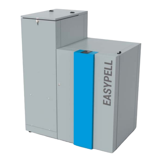
- Page 1 Installation Manual Easypell 16 - 32 kW ENGLISH 200014EN www.easypell.com...
- Page 2 Title: Installation Manual Easypell 16 - 32 kW Article number: 200014EN 2.0 Version valid from: 07/2022 Approved: Christian Wohlinger Author Eco Engineering 2050 GmbH A-4133 Niederkappel, Gewerbepark 1 E-Mail: office@easypell.com © by Eco Engineering 2050 GmbH www.easypell.com Subject to modifcations...
-
Page 3: Table Of Contents
Operation of a pellet boiler with an existing boiler Warnings and safety instructions Basic safety instructions Warning signs What to do in an emergency 6 The Easypell Bringing the pellet boiler into the central heating room Transport Notes on bringing the unit into the building Casing parts Removing the casing, the hopper and the burner 7.4.1... -
Page 4: Dear Customer
1 Dear Customer Dear Customer This manual is intended to help you operate the product safely, properly and eco- • nomically. Please read this manual right through and take note of the safety warnings. • Keep all documentation supplied with this unit in a safe place for future reference. •... -
Page 5: Intended Use
Reasonable foreseeable inadvertent uses for the heating system are not known. The Easypell complies with all directives, regulations and standards relevant for this type of equipment within the scope of the declaration of conformity of the CE marking. - Page 6 2 Intended use Installation Manual...
-
Page 7: Types Of Safety Warning Sign
3 Types of safety warning sign Types of safety warning sign The warning signs use the following symbols and texts. Types of safety warning sign Risk of injury Consequences of risk Avoiding risk DANGER Danger - indicates a situation that could lead to death or lifethreatening injury. ▶... -
Page 8: Prerequisites For Installing A Pellet Boiler
4 Prerequisites for installing a pellet boiler Prerequisites for installing a pellet boiler You must fulfill the following conditions before operating a fully automatic pellet boiler. Guidelines and standards for installing a pellet boiler Overview of standards and guidelines applying to the installation of a pellet boiler. Check whether you need to obtain planning permission or approval from the authori- ties for installing a new heating system or changing your existing system. -
Page 9: Central Heating Room
4 Prerequisites for installing a pellet boiler Central heating room The pellet boiler is installed in the central heating room. Safety instructions for the heating room DANGER Risk of fire Do not store flammable materials or liquids in the vicinity of the pellet boiler. Do not permit unauthorised persons to enter the central heating room - children are to be kept out. -
Page 10: Flue Gas System
The flue system must be designed in accordance with local regulations or ÖNORM EN 13384-1. The flue pipe must be insulated and must rise to the chimney and be as short as possible. Boiler size Easypell 16 Easypell 20 Easypell 25 Easypell 32 Flue gas tube diameter (at boiler) –... -
Page 11: Safety Systems
4 Prerequisites for installing a pellet boiler Safety systems The following safety measures are the prerequisite for safe operation of your sys- tem. Emergency stop switch Every heating system must be able to be switched off with an Emergency Stop switch. -
Page 12: Warnings And Safety Instructions
5 Warnings and safety instructions Warnings and safety instructions Observing safety instructions ensures that the heating system is operated safely. Basic safety instructions Never get yourself into danger; give own safety the utmost priority. • Keep children away from the central heating room and storage room. •... - Page 13 5 Warnings and safety instructions WARNING Risk of burns Do not touch the flue spigot or the flue gas tube. Do not reach into the ash chamber. Use gloves to empty the ash box. Do not clean the boiler until it has been allowed to cool down.
-
Page 14: What To Do In An Emergency
5 Warnings and safety instructions What to do in an emergency What to do in the event of a fire Switch off the heating system. • Call the fire brigade • Use approved fire extinguishers (fire protection class ABC). • What to do if you smell smoke Switch off the heating system. -
Page 15: The Easypell
Eco Engineering offers the Easypell with the following power ratings: 16, 20, 25 and 32kW. Refer to the data plate for the power rating of your Easypell. The data plate is located on the rear side of the boiler. Here you find the type designation, manufacturer's serial number and year of build. - Page 16 6 The Easypell Burner plate Suction fan Flame tube Anti-blowback system Heat exchanger Burner auger Boiler water Electronic ignition Boiler insulation Combustion chamber sensor Combustion chamber cover Ash box Installation Manual...
-
Page 17: Bringing The Pellet Boiler Into The Central Heating Room
Make sure that the pellet boiler is located under a roof if it needs to be stored outside before it is transported/brought into the building. Minimum door width — max. unit dimension Easypell 16 / 20 16 – 20 kW 677 mm Easypell 25 / 32 25 –... - Page 18 7 Bringing the pellet boiler into the central heating room Boiler dimensions 90 mm Dimensions in mm Easypell 16 Easypell 20 Easypell 25 Easypell 32 A: flow & return 1120 1310 B: overall width of pellet boiler 1145 1145 C: Width of boiler casing...
-
Page 19: Casing Parts
Legislation in your country must be observed! The indicated values must not fall below by piping or other. Casing parts Die Verkleidungsteile umgeben den Kessel. Sie verhindern den Kontakt zu heißen, beweglichen und stromführenden Bauteilen. Sie geben dem Pelletkessel Easypell das unverwechselbare Aussehen. Installation Manual... -
Page 20: Removing The Casing, The Hopper And The Burner
7 Bringing the pellet boiler into the central heating room Pellet hopper casing cover Boiler door Boiler casing cover Pellet hopper casing Boiler side panel Cover pellet hopper casing Front of boiler Boiler rear panel Removing the casing, the hopper and the burner Dismantle the pellet boiler as far as necessary if site conditions require, so that the unit can be brought safely into the building. -
Page 21: Dismantling The Burner Casing And Burner
7 Bringing the pellet boiler into the central heating room 7.4.1 Dismantling the burner casing and burner Installation Manual... -
Page 22: Dismantling The Boiler Door
7 Bringing the pellet boiler into the central heating room 7.4.2 Dismantling the boiler door Installation Manual... -
Page 23: Dismantling The Boiler Casing
7 Bringing the pellet boiler into the central heating room 7.4.3 Dismantling the boiler casing Installation Manual... -
Page 24: Change Position Of Flue Gas Fan
7 Bringing the pellet boiler into the central heating room Change position of flue gas fan Installation Manual... -
Page 25: Performance Adjustment
Heat transfer takes place in the heat exchanger tubes. The heat exchanger tubes are fitted with cleaning springs that also act as turbolators. On the Easypell 16 and Easypell 25 boilers, some of these heat exchangers are sealed off with sealing caps. - Page 26 32 kW 25 kW Insert another 4 turbulators Only the adjustment of the system by an authorized Eco Engineering service techni- cian can guarantee an optimal level of efficiency and with that a low-emission opera- tion. Starting up for the first time has to be performed only by an authorized Eco Engi- neering service technician.
-
Page 27: Connecting Up The Hydraulics
The flow and return pipes must be insulated according to the state of the art. Hydraulic schematics Always refer to the Eco Engineering hydraulic schematics when connecting up the pellet boiler. The Eco Engineering hydraulic schematics are available from your Eco Engineering sales partner or from the Eco Engineering website. - Page 28 9 Connecting up the hydraulics Feed Return Drain connection Safety valve Expansion tank Two T-pieces are located in the ash pan and must be mounted directly on the hydraulic connection during installation. Installation Manual...
-
Page 29: Fuses - Boiler Controller
10 Fuses - boiler controller Fuses - boiler controller The boiler controller is located behind the front cover of the boiler. It is used to con- trol the combustion procedere and the fuel-feeding system. The boiler controller is connected to the operating device by a bus-connection. The operating device is located in the boiler door. -
Page 30: Plugs On The Boiler Control Unit
10 Fuses - boiler controller Fuse type secured terminals F1: Fuse T 3,15A LUFT, ES, ZUEND 2 F2: Fuse T 3,15A UW, RM, SZ 3 F3: Fuse T 315mA internal supply 4 F5: Fuse T 1A Z28, Z30 NOTICE Damage of property If you change microfuses, ensure correct current rating 10.1 Plugs on the boiler control unit... -
Page 31: Cable Routing
10 Fuses - boiler controller Designation of plug-in posi- Voltage Name of sensors, motors and pumps tion Z25 (BSK) 1 2 3 4 5 6 24 Volt Flame return gate (Belimo) Z16 (UW) 13 PE N 230 Volt DHW pump/ Accumulator pump Z17 (HK) N PE 14 230 Volt... -
Page 32: Wiring Diagrams
10 Fuses - boiler controller DANGER Risk of electric shock Switch off the system before performing work on the boiler. Note the following points to ensure the cables are routed securely: Cables must not be routed: • over moving parts over hot parts •... - Page 33 10 Fuses - boiler controller DANGER Risk of electric shock Only a qualified person may connect the pellet boiler to the power supply. Always disconnect / de-energize the power supply before working on the boiler. Installation Manual...
- Page 34 10 Fuses - boiler controller Installation Manual...
-
Page 35: Starting Up For The First Time
Density of the combustion chamber To ensure a trouble-free operation, the density of the combustion chamber must be given. The unit must be started up for the first time by an authorised Eco Engineering serv- ice technician. NOTICE Material Damage The allowed operation temperature of the boiler controller is between 5 and 40°... -
Page 36: Starting The Pellet Boiler
12 Starting the pellet boiler Starting the pellet boiler Navigation-icons Icon view Description Use the up arrow to return to the previous menu screen. Use the down arrow to arrive at the next menu screen. When this symbol is displayed, the set value can be changed. - Page 37 12 Starting the pellet boiler Icons System status Icon view Description Run down time Negative draft input open Accumulator Sensor break accumulator sensor Boiler Sensor break DHW sensor Boiler cleaning Note: This message appears when the container cover has been open for longer than 20 sec- onds.
- Page 38 12 Starting the pellet boiler Icon view Description Burner contact closed Pump active Temperarure too low Outertemperature control Installation Manual...
-
Page 39: Controller For Heating Circuits And Dhw
13 Controller for heating circuits and DHW Controller for heating circuits and DHW In principle, 5 versions are available: Version A: Burner demand via contact Z26, Pump on the output Z16, no DHW. Version B: Heating circuit direct via thermostat, DHW regulation. Version C: Heating circuit and DHW regulation. -
Page 40: Version A
13 Controller for heating circuits and DHW 13.2 Version A The boiler is started via the burner contact. The pumps at output Z16 (UW) are active from a boiler temperature of 60° C. The mode of the pumps can be selected. External heating controller For an external heating controller, input Z26 is determined as burner demand. - Page 41 13 Controller for heating circuits and DHW optional optional outdoor-sensor external heating burner- contact- Z26 controller boiler- sensor Heat consumers are shown symbolically and can be substituted by others! NOTICE It must be ensured that the heating circuit pump only switches on from 60°C boiler temperature.
- Page 42 13 Controller for heating circuits and DHW Wiring diagram version A: The total line length of the heating circuit pumps must not exceed 100 m! Installation Manual...
-
Page 43: Commissioning Controller Version A
13 Controller for heating circuits and DHW 13.2.1 Commissioning controller version A After code input: Display of the current boiler temperature Setting the boiler set temperature. The boiler set temperature can be set in the range of 70 ° C to 90 ° C if a higher boiler temperature requirement or a larger modulation range is required. - Page 44 13 Controller for heating circuits and DHW Adjusting the time programme of the boiler. By pressing the start and stoptime appear. Activate the times with In the activated time, the boiler always runs up to the switch-off temperature without considering the contact Z26.
- Page 45 13 Controller for heating circuits and DHW Setting temperature unit. ° Celsius • ° Fahrenheit • Setting mode burner request. Conversion from constant ON / OFF to pulse mode. In pulse mode, the boiler runs according to the start pulse until it reaches the shut off temper- ature.
- Page 46 13 Controller for heating circuits and DHW Display of the current values KT: Boiler temperature • FRT: Combustion chamber temperature • • UP: Negative draft STB: Safety temperature sensor • EP: Supply/Pause time • FRT S: Set combustion chamber temp •...
- Page 47 13 Controller for heating circuits and DHW Extended insertion When this action is activated, the pellets are pushed in for a maximum of 3 ignition cycles lon- ger than standard during the next ignition. This function is automatically reset after being acti- vated once and is used for faster ignition when the burner screw is empty.
- Page 48 13 Controller for heating circuits and DHW Display of current boiler status. Current boiler temperature Boiler set temperature Installation Manual...
-
Page 49: Version B
13 Controller for heating circuits and DHW 13.3 Version B Heating circuits can switch on the burner demand via room thermostats directly in the pump line. When the boiler reaches 60° C, a signal is output to Z17 (HK After the thermostat interrupts the pump supply, the boiler switches off when the end temper- ature is reached. - Page 50 13 Controller for heating circuits and DHW Wiring diagram version B: The total line length of the heating circuit pumps must not exceed 100 m! Installation Manual...
-
Page 51: Commissioning Controller Version B
13 Controller for heating circuits and DHW 13.3.1 Commissioning controller version B After code input: Anzeige der aktuellen Kesseltemperatur Setting the boiler set temperature. The boiler set temperature can be set in the range of 70° C to 90° C if a higher boiler temperature requirement or a larger modulation range is required. - Page 52 13 Controller for heating circuits and DHW Display of the current DHW temperature. Setting the DHW set temperature. The DHW set temperature can be set in the range of 30° C to 75° C. Setting DHW priority. During the hot water times, the heating circuits are only switched on when no hot water is demanded.
- Page 53 13 Controller for heating circuits and DHW Setting the time programm of the DHW. By pressing the start and stoptime appear. Activate the times with During the activated time, the boiler regulates to the values indicated by the hot water sensor. The hot water control is not activated outside the set times! Setting Outertemperature control.
- Page 54 13 Controller for heating circuits and DHW Settings pumptype: Z16/38 • Heating efficient with or without PWM1 - PWM signal heating Asynchronus pump – direct output 230VAC • on/off • Heating efficient PWM 2 – PWM signal solar Setting temperature unit. °...
- Page 55 13 Controller for heating circuits and DHW Display of the current values KT: Boiler temperature • FRT: Combustion chamber temperature • • UP: Negative draft STB: Safety temperature sensor • EP: Supply/Pause time • FRT S: Set combustion chamber temp •...
- Page 56 13 Controller for heating circuits and DHW Extended insertion When this action is activated, the pellets are pushed in for a maximum of 3 ignition cycles lon- ger than standard during the next ignition. This function is automatically reset after being acti- vated once and is used for faster ignition when the burner screw is empty.
- Page 57 13 Controller for heating circuits and DHW Anzeige aktueller Kesselstatus. Current boiler temperature Boiler set temperature Current DHW temperature 4. DHW set temperature Installation Manual...
-
Page 58: Version C
13 Controller for heating circuits and DHW 13.4 Version C Up to 3 heating circuits can be demanded via room thermostats or time program. A room thermostat (ON / OFF) can be connected via the inputs X26, X27 and X28. The 230V supply of the pumps is provided via output Z17 (HK) (boiler temperature>... - Page 59 13 Controller for heating circuits and DHW Wiring diagram version C: The total line length of the heating circuit pumps must not exceed 100 m! Installation Manual...
-
Page 60: Commissioning Controller Version C
13 Controller for heating circuits and DHW 13.4.1 Commissioning controller version C After code input: Display of the current boiler temperature Setting the boiler set temperature. The boiler set temperature can be set in the range of 70 ° C to 90 ° C if a higher boiler temperature requirement or a larger modulation range is required. - Page 61 13 Controller for heating circuits and DHW Setting the time programm of heating circuit 1. By pressing the start and stoptime appear. Activate the times with During the activated time, the boiler always runs up to the switch-off temperature without consider- ing the Z26 contact.
- Page 62 13 Controller for heating circuits and DHW Setting the power of heating circuit pump 2. The power range can be set between 30 - 100%. For normal use, a setting of 30 - 70% should be selected. When adjusting too excessive noises can appear. Setting the time programm of heating circuit 3.
- Page 63 13 Controller for heating circuits and DHW Display of the current DHW temperature. Setting the DHW set temperature. The DHW set temperature can be set in the range of 30° C to 75° C. Setting DHW priority. During the hot water times, the heating circuits are only switched on when no hot water is demanded.
- Page 64 13 Controller for heating circuits and DHW Setting the time programm of the DHW. By pressing the start and stoptime appear. Activate the times with During the activated time, the boiler regulates to the values indicated by the hot water sensor. The hot water control is not activated outside the set times! Setting Outertemperature control.
- Page 65 13 Controller for heating circuits and DHW Setting temperature unit. ° Celsius • • ° Fahrenheit Setting operation mode. Changing the operation mode. Installation Manual...
- Page 66 13 Controller for heating circuits and DHW Display of the current values KT: Boiler temperature • FRT: Combustion chamber temperature • • UP: Negative draft STB: Safety temperature sensor • EP: Supply/Pause time • FRT S: Set combustion chamber temp •...
- Page 67 13 Controller for heating circuits and DHW Extended insertion When this action is activated, the pellets are pushed in for a maximum of 3 ignition cycles lon- ger than standard during the next ignition. This function is automatically reset after being acti- vated once and is used for faster ignition when the burner screw is empty.
- Page 68 13 Controller for heating circuits and DHW Display of current boiler status. Heating circuit 1 Heating circuit 2 Heating circuit 3 4. Current boiler temperature Boiler set temperature Current DHW temperature DHW set temperature Installation Manual...
-
Page 69: Version D
13 Controller for heating circuits and DHW 13.5 Version D The accumulator sensor is connected to terminal Z37. The burner demand regulates the accumulator temperature. The pump output X16 (UW) and X38 (PWM) are used for the boiler controlled pump, which is not active below 60°... - Page 70 13 Controller for heating circuits and DHW Wiring diagram version D: The total line length of the heating circuit pumps must not exceed 100 m! Installation Manual...
-
Page 71: Commissioning Controller Version D
13 Controller for heating circuits and DHW 13.5.1 Commissioning controller version D After code input: Display of the current boiler temperature Setting the boiler set temperature. The boiler set temperature can be set in the range of 70 ° C to 90 ° C if a higher boiler temperature requirement or a larger modulation range is required. - Page 72 13 Controller for heating circuits and DHW Setting the time programm of heating circuit 1. By pressing the start and stoptime appear. Activate the times with During the activated time, the boiler always runs up to the switch-off temperature without consider- ing the Z27 contact.
- Page 73 13 Controller for heating circuits and DHW Setting the power of heating circuit pump 2. The power range can be set between 30 - 100%. For normal use, a setting of 30 - 70% should be selected. When adjusting too excessive noises can appear. Display of the current DHW temperature.
- Page 74 13 Controller for heating circuits and DHW Setting DHW priority. During the hot water times, the heating circuits are only switched on when no hot water is demanded. Setting DHW hysteresis. The DHW hysteresis can be set between 5K and 20 Setting the time programm of the DHW.
- Page 75 13 Controller for heating circuits and DHW Setting the accumulator set temperature. Note: The accumulator set temperature can be set in the range of 30° C to 75° C. Setting hysteresis Accumulator set temperature The accumulator hysteresis can bet set between 5 K and 20 K.
- Page 76 13 Controller for heating circuits and DHW Setting Outertemperature control. Here you can set the temperature values for the maximum and minimum boiler rating. Adjustment range max. rated power -10° C bis +6° Adjustment range min. power +7° C bis +25° C Setting boiler rated power.
- Page 77 13 Controller for heating circuits and DHW Setting operation mode. Changing the operation mode. Installation Manual...
- Page 78 13 Controller for heating circuits and DHW Display of the current values KT: Boiler temperature • FRT: Combustion chamber temperature • • UP: Negative draft STB: Safety temperature sensor • EP: Supply/Pause time • FRT S: Set combustion chamber temp •...
- Page 79 13 Controller for heating circuits and DHW Extended insertion When this action is activated, the pellets are pushed in for a maximum of 3 ignition cycles lon- ger than standard during the next ignition. This function is automatically reset after being acti- vated once and is used for faster ignition when the burner screw is empty.
- Page 80 13 Controller for heating circuits and DHW Display of current boiler status. Heating circuit 1 Heating circuit 2 4. Current accumulator temperature currently demanded accumulator set tempera- ture from the boiler (depending on current demand) Accumulator set temperature eating circuit-Pump on temperature Current boiler temperature Boiler set temperature 10.
-
Page 81: Version E
13 Controller for heating circuits and DHW 13.6 Version E The accumulator sensor is connected to terminal Z37. The set accumulator temperature regulates the burner demand. The pump output X16 (UW) and X38 (PWM) are used for the boiler controlled pump, which is not active below 60°... - Page 82 13 Controller for heating circuits and DHW Wiring diagram version E: The total line length of the heating circuit pumps must not exceed 100 m! Installation Manual...
-
Page 83: Commissioning Controller Version E
13 Controller for heating circuits and DHW 13.6.1 Commissioning controller version E After code input: Display of the current boiler temperature Setting the boiler set temperature. The boiler set temperature can be set in the range of 70 ° C to 90 ° C if a higher boiler temperature requirement or a larger modulation range is required. - Page 84 13 Controller for heating circuits and DHW Setting the time programm of heating circuit 1. By pressing the start and stoptime appear. Activate the times with During the activated time, the boiler always runs up to the switch-off temperature without consider- ing the Z26 contact.
- Page 85 13 Controller for heating circuits and DHW Setting DHW priority. During the hot water times, the heating circuits are only switched on when no hot water is demanded. Setting DHW hysteresis. The DHW hysteresis can be set between 5K and 20 Setting the time programm of the DHW.
- Page 86 13 Controller for heating circuits and DHW Display current accumulator temperature. Setting the accumulator set temperature. Note: The accumulator set temperature can be set in the range of 30° C to 75° C. Setting hysteresis Accumulator set temperature The accumulator hysteresis can bet set between 5 K and 20 K.
- Page 87 13 Controller for heating circuits and DHW Setting Outertemperature control. Here you can set the temperature values for the maximum and minimum boiler rating. Adjustment range max. rated power -10° C bis +6° Adjustment range min. power +7° C bis +25° C Setting boiler rated power.
- Page 88 13 Controller for heating circuits and DHW Setting temperature unit. ° Celsius • • ° Fahrenheit Setting operation mode. Changing the operation mode. Installation Manual...
- Page 89 13 Controller for heating circuits and DHW Display of the current values KT: Boiler temperature • FRT: Combustion chamber temperature • • UP: Negative draft STB: Safety temperature sensor • EP: Supply/Pause time • FRT S: Set combustion chamber temp •...
- Page 90 13 Controller for heating circuits and DHW Extended insertion When this action is activated, the pellets are pushed in for a maximum of 3 ignition cycles lon- ger than standard during the next ignition. This function is automatically reset after being acti- vated once and is used for faster ignition when the burner screw is empty.
- Page 91 13 Controller for heating circuits and DHW Display of current boiler status. Heating circuit 1 Current accumulator temperature 4. currently demanded accumulator set tempera- ture from the boiler (depending on current demand) Accumulator set temperature Heating circuit-Pump on temperature Current boiler temperature Boiler set temperature Current DHW temperature 10.
-
Page 92: Setting The Time Program
13 Controller for heating circuits and DHW 13.7 Setting the time program • Heating period 1 Heating period 2 • Press the confirm button to request a change, then use the arrow key to select the desired value and select it with the confirmation button. The value can be raised or lowered by pressing the keys Confirm with... -
Page 93: Default Values And Settings
14 Default values and settings Default values and settings Default Minimum Maximum Pump type – Boiler controlled pump Energy-efficient Boiler control temperature 70 °C 70 °C 90 °C Switch off temperature 76 °C 76 °C 95 °C Outdoor sensor min power 8 °C 7 °C 25 °C... -
Page 94: Spare Parts
15 Spare parts Spare parts PE243 307621 PE212 307444 PE289 PE174 PE684 PE429 PE473 307389 PE471 PE142 307419 E1204-1 200005 302707 307609 307800 PE103 200003 PE273 307608 PE129 307442 E1001A 307421 121250 309702 200048 PE215 307418 121253 24155 210127 041071 307561 E1073 121114... - Page 95 15 Spare parts PE243 309121 PE213 309066 PE290 PE174 PE430 PE684 PE474 PE472 309073 PE142 308895 308921 E1204-1 200005 PE103 308975 310614 200003 PE130 PE273 308976 308878 E1001A 308893 309702 121250 200048 PE2151 121253 308897 24155 210127 041071 E1073 308903 121114 B104 121122...
-
Page 96: Technical Data
16 Technical data Technical data Information according to EU regulation 2015/1187 and 2015/1189 Model designation Easypell Manufacturer and contact details Eco Engineering 2050 GmbH Mühlgasse 9, 4132 Lembach, Austria Heat-up mode Automatically Condensing boiler Solid fuel boiler with cogeneration system... - Page 97 16 Technical data Model designation Easypell Annual space heating emissions < 40 PM [mg/m < 20 OGC [mg/m < 500 CO [mg/m < 200 NOx [mg/m Auxiliary power consumption Auxiliary power consumption at nominal heat power Auxiliary power consumption at 30 % of nominal heat...
- Page 98 16 Technical data Model designation Easypell Flue gas area (Flue gas = F.g.) Combustion chamber temperature [°C] 500 - 870 Need of draught rated power [mBar] 0,08 Flue gas temperature partial load [mBar] 0,03 Flue gas temp. rated power [°C] Flue gas temp.
- Page 99 16 Technical data Model designation Easypell Chimney calculation Rated heating power [kW] Firing thermal capacity nominal load [kW] 17,13 21,28 26,71 33,51 CO2 volume concentration nominal load [%] 14,1 13,6 13,2 13,0 Flue gas iniertia current for chimney calculation nominal...
- Page 100 16 Technical data Model designation Easypell Electrical Components Connection value 230 VAC, 50Hz Main Drive [W] Combustion Air Blower [W] Flue gas fan [W] Electrical Ignition – [W] Cleaning Motor [W] Flame Return Gate [W] Noise generation [dB] 43,7 ± 3,2...
Need help?
Do you have a question about the Easypell and is the answer not in the manual?
Questions and answers