Table of Contents
Advertisement
Quick Links
Advertisement
Table of Contents

Related Manuals for Eco Engineering Easypell


Summary of Contents for Eco Engineering Easypell
- Page 1 Operating Manual Easypell 16 - 32 kW ENGLISH 200013EN www.easypell.com...
- Page 2 Title: Operating Manual Easypell 16 - 32 kW Article number: 200013EN 2.0 Version valid from: 07/2022 Approved: Christian Wohlinger Author Eco Engineering 2050 GmbH A-4133 Niederkappel, Gewerbepark 1 E-Mail: office@easypell.com © by Eco Engineering 2050 GmbH www.easypell.com Subject to modifcations...
-
Page 3: Table Of Contents
Central heating room Safety systems Operation of a pellet boiler with an existing boiler 6 Fuel Specification for high quality pellets as per EN ISO 17225–2, class A1 The Easypell Maintenance and servicing Maintenance 8.1.1 Emptying of the ash box 8.1.2... -
Page 4: Dear Customer
1 Dear Customer Dear Customer This manual is intended to help you operate the product safely, properly and eco- • nomically. Please read this manual right through and take note of the safety warnings. • Keep all documentation supplied with this unit in a safe place for future reference. •... -
Page 5: Intended Use
2 Intended use Intended use The pellet heating system is designed to heat water for central or other indirect heat- ing systems and hot water supply for buildings. It is not permissible to use the pellet heating system for any other purpose. Reasonable foreseeable inadvertent uses for the heating system are not known. -
Page 6: Types Of Safety Warning Sign
3 Types of safety warning sign Types of safety warning sign The warning signs use the following symbols and texts. Types of safety warning sign Risk of injury Consequences of risk Avoiding risk DANGER Danger - indicates a situation that could lead to death or lifethreatening injury. ▶... -
Page 7: Warnings And Safety Instructions
4 Warnings and safety instructions Warnings and safety instructions Observing safety instructions ensures that the heating system is operated safely. Basic safety instructions Never get yourself into danger; give own safety the utmost priority. • Keep children away from the central heating room and storage room. •... - Page 8 4 Warnings and safety instructions WARNING Risk of burns Do not touch the flue spigot or the flue gas tube. Do not reach into the ash chamber. Use gloves to empty the ash box. Do not clean the boiler until it has been allowed to cool down.
-
Page 9: What To Do In An Emergency
4 Warnings and safety instructions What to do in an emergency What to do in the event of a fire Switch off the heating system. • Call the fire brigade • Use approved fire extinguishers (fire protection class ABC). • What to do if you smell smoke Switch off the heating system. -
Page 10: Prerequisites For Installing A Pellet Boiler
5 Prerequisites for installing a pellet boiler Prerequisites for installing a pellet boiler You must fulfill the following conditions before operating a fully automatic pellet boiler. Central heating room The pellet boiler is installed in the central heating room. Safety instructions for the heating room DANGER Risk of fire Do not store flammable materials or liquids in the vicinity of the pellet boiler. -
Page 11: Safety Systems
5 Prerequisites for installing a pellet boiler NOTICE Oxidation of chimney Do not use metal brushes to clean chimneys made of stainless steel. ▶ Legislation in your country must be observed. Safety systems The following safety measures are the prerequisite for safe operation of your sys- tem. -
Page 12: Fuel
6 Fuel Fuel Wood pellets are natural wood (dried sawdust or waste from machining) that has been formed into pellets under high pressure. They have a very low moisture content and very high calorific value. Manufacture of wood pellets is regulated by European standard EN ISO 17225–2. Specification for high quality pellets as per EN ISO 17225–2, class A1 Calorific value... -
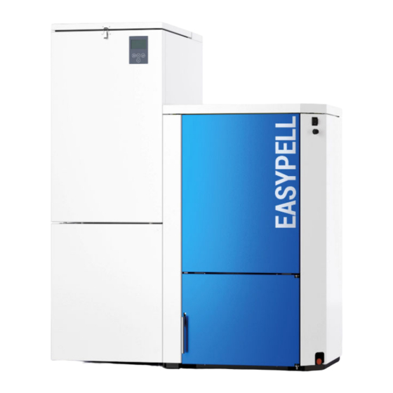
Page 13: The Easypell
Eco Engineering offers the Easypell with the following power ratings: 16, 20, 25 and 32kW. Refer to the data plate for the power rating of your Easypell. The data plate is located on the rear side of the boiler. Here you find the type designation, manufacturer's serial number and year of build. - Page 14 7 The Easypell Burner plate Suction fan Flame tube Anti-blowback system Heat exchanger Burner auger Boiler water Electronic ignition Boiler insulation Combustion chamber sensor Combustion chamber cover Ash box Operating Manual...
-
Page 15: Maintenance And Servicing
8 Maintenance and servicing Maintenance and servicing Regular checks of the pellet heating system are a prerequisite for reliable, efficient and environment-friendly operation. Maintenance Maintenance, boiler cleaning and cleaning of flue gas connection are necessary at least once a year. Pelletswhich produces tendentially more slagging (ash melting point <1300 °... - Page 16 8 Maintenance and servicing Operating Manual...
-
Page 17: Discharging The Hopper
8 Maintenance and servicing 8.1.2 Discharging the hopper Cleaning the boiler every year Boiler cleaning and inspection must be carried out once every heating season. WARNING Risk of burns Do not clean the boiler until it has been allowed to cool down. Switch off the heating system at least 6 hours before opening the boiler. - Page 18 8 Maintenance and servicing Procedure for cleaning the boiler Operating Manual...
- Page 19 8 Maintenance and servicing NOTICE Reduction in boiler performance and damage to pellet boiler due to blockages in the air inlet Clean the air intakes, the burner plate and the flame tube. Operating Manual...
- Page 20 8 Maintenance and servicing Cleaning the Induced draft blower: Operating Manual...
-
Page 21: Operating The Heating System
9 Operating the heating system Operating the heating system NOTICE Damage caused do to incorrect operation or incorrect settings. Only trained operators may use the heating system. Make sure no unauthorised persons enter the central heating room. Keep children away from the central heating room and storage room. DANGER Fire risk Keep the boiler door closed while the boiler is in operation. -
Page 22: User Controls And Their Function
10 User controls and their function User controls and their function Navigation-icons Icon view Description Use the up arrow to return to the previous menu screen. Use the down arrow to arrive at the next menu screen. When this symbol is displayed, the set value can be changed. - Page 23 10 User controls and their function Icons System status Icon view Description Run down time Negative draft input open Accumulator Sensor break accumulator sensor Boiler Sensor break DHW sensor Boiler cleaning Note: This message appears when the container cover has been open for longer than 20 sec- onds.
- Page 24 10 User controls and their function Icon view Description Burner contact closed Pump active Temperarure too low Outertemperature control Operating Manual...
-
Page 25: Version A
10 User controls and their function 10.1 Version A After switching on, the boiler starts (after approx. 10 seconds). The fire protection device is opened. This symbol appears on the display while the fire protection device is being opened (approx. 2 minutes). - Page 26 10 User controls and their function On completion of the ignition process (can last up to 15 minutes), the symbol for heating at full power appears. The boiler is now heating at full power. Display of the current boiler temperature Adjusting the time programme of the boiler.
- Page 27 10 User controls and their function Setting current time. Press to set the current time. Confirm with Display of current boiler status. Current boiler temperature Boiler set temperature Operating Manual...
-
Page 28: Version B
10 User controls and their function 10.2 Version B After switching on, the boiler starts (after approx. 10 seconds). The fire protection device is opened. This symbol appears on the display while the fire protection device is being opened (approx. 2 minutes). - Page 29 10 User controls and their function On completion of the ignition process (can last up to 15 minutes), the symbol for heating at full power appears. The boiler is now heating at full power. Display of the current boiler temperature Display of the current DHW temperature.
- Page 30 10 User controls and their function Setting the time programm of the DHW. By pressing the start and stoptime appear. Activate the times with During the activated time, the boiler regulates to the values indicated by the hot water sensor. The hot water control is not activated outside the set times! Setting Outertemperature control.
- Page 31 10 User controls and their function Display of current boiler status. Current boiler temperature Boiler set temperature Current DHW temperature 4. DHW set temperature Operating Manual...
-
Page 32: Version C
10 User controls and their function 10.3 Version C After switching on, the boiler starts (after approx. 10 seconds). The fire protection device is opened. This symbol appears on the display while the fire protection device is being opened (approx. 2 minutes). - Page 33 10 User controls and their function On completion of the ignition process (can last up to 15 minutes), the symbol for heating at full power appears. The boiler is now heating at full power. Display of the current boiler temperature Setting the time programm of heating circuit 1.
- Page 34 10 User controls and their function Setting the time programm of heating circuit 3. By pressing the start and stoptime appear. Activate the times with During the activated time, the boiler always runs up to the switch-off temperature without consider- ing the Z28 contact.
- Page 35 10 User controls and their function Setting the time programm of the DHW. By pressing the start and stoptime appear. Activate the times with During the activated time, the boiler regulates to the values indicated by the hot water sensor. The hot water control is not activated outside the set times! Setting Outertemperature control.
- Page 36 10 User controls and their function Display of current boiler status. Heating circuit 1 Heating circuit 2 Heating circuit 3 4. Current boiler temperature Boiler set temperature Current DHW temperature DHW set temperature Operating Manual...
-
Page 37: Version D
10 User controls and their function 10.4 Version D After switching on, the boiler starts (after approx. 10 seconds). The fire protection device is opened. This symbol appears on the display while the fire protection device is being opened (approx. 2 minutes). - Page 38 10 User controls and their function On completion of the ignition process (can last up to 15 minutes), the symbol for heating at full power appears. The boiler is now heating at full power. Display of the current boiler temperature Adjusting the time programme of the heating cir- cuit 1.
- Page 39 10 User controls and their function Display of the current DHW temperature. Setting the DHW set temperature. The DHW set temperature can be set in the range of 30° C to 75° C. Setting the time programm of the DHW. By pressing the start and stoptime appear.
- Page 40 10 User controls and their function Display current accumulator temperature. Setting the accumulator set temperature. The accumulator set temperature can be set in the range of 30° C to 75° C. Setting Outertemperature control. Here you can set the temperature values for the maximum and minimum boiler rating.
- Page 41 10 User controls and their function Display of current boiler status. Heating circuit 1 Heating circuit 2 4. Current accumulator temperature currently demanded accumulator set tempera- ture from the boiler (depending on current demand) Accumulator set temperature Heating circuit-Pump on temperature Current boiler temperature Boiler set temperature 10.
-
Page 42: Version E
10 User controls and their function 10.5 Version E After switching on, the boiler starts (after approx. 10 seconds). The fire protection device is opened. This symbol appears on the display while the fire protection device is being opened (approx. 2 minutes). - Page 43 10 User controls and their function On completion of the ignition process (can last up to 15 minutes), the symbol for heating at full power appears. The boiler is now heating at full power. Display of the current boiler temperature Adjusting the time programme of the heating cir- cuit 1.
- Page 44 10 User controls and their function Setting the DHW set temperature. The DHW set temperature can be set in the range of 30° C to 75° C. Setting the time programm of the DHW. By pressing the start and stoptime appear. Activate the times with During the activated time, the boiler regulates to the values indicated by the hot water sensor.
- Page 45 10 User controls and their function Setting the accumulator set temperature. The accumulator set temperature can be set in the range of 30° C to 75° C. Setting Outertemperature control. Here you can set the temperature values for the maximum and minimum boiler rating. Adjustment range max.
-
Page 46: Setting The Time Program
10 User controls and their function Display of current boiler status. Heating circuit 1 Current accumulator temperature 4. currently demanded accumulator set tempera- ture from the boiler (depending on current demand) Accumulator set temperature Heating circuit-Pump on temperature Current boiler temperature Boiler set temperature Current DHW temperature 10. -
Page 47: Setting The Time
10 User controls and their function 10.7 Setting the time The current time is displayed. The setting of the time is analog to the setting of the time programes! Operating Manual... -
Page 48: Malfunctions
11 Malfunctions Malfunctions 11.1 Malfunctions - what to do Follow the sequence described for handling malfunctions. • The heating system switches off automatically if a malfunction occurs. The control unit display shows a malfunction alarm text. • You have to rectify the cause of the malfunction. •... - Page 49 11 Malfunctions Overview of malfunction alarm texts: Display: Error code: Description: Boiler sensor fracture, measuring circuit from boiler sensor is open Cause and Remedy: sensor not connected connect sensor at input ► sensor defect measure sensor (approx. 2kΩ ► at 25°C) replace if required sensor cable defect replace sensor ►...
- Page 50 11 Malfunctions Display: Error code: Description: Negative draft input open, measuring circuit from negative draft meas- urement open Cause and Remedy: signal incorrect check polarity and signal ► (0-10V) signal cable defect replace sensor ► signal too low signal below 0V ►...
- Page 51 11 Malfunctions Display: Error code: Description: Safety temperature limiter has tripped Cause and Remedy: safety temperature limiter connect up safety temperature unplugged limiter and check cable con- ► nections safety temperature limiter has check boiler controller ► tripped safety temperature limiter allow boiler to cool and reset ►...
- Page 52 11 Malfunctions Display: Error code: Description: Flame return gate open fault. Cause and Remedy: flame return gate unplugged Connect up flame return gate ► and check cable connections Flame return gate does not check ball valve to see if it is ►...
- Page 53 11 Malfunctions Display: Error code: Description: Container cover open Cause and Remedy: Cover open close cover ► End-switch defect replace end-switch ► Display: Error code: Description: DHW sensor fracture, measuring circuit from DHW sensor is open Cause and Remedy: sensor not connected connect sensor at input ►...
- Page 54 11 Malfunctions Display: Error code: Description: Sensor break accumulator sensor, measuring circuit of acculmulator sensor is open Cause and Remedy: sensor not connected connect sensor at input ► sensor defect measure sensor (approx. 2kΩ ► at 25°C) if required sensor cable defect replace sensor ►...
-
Page 55: Maintenance Intervals
• Only authorised specialists may carry our repair work on this system. Use original Eco Engineering spare parts only. • Not using original Eco Engineering parts will cause the warranty to become void. • 11.5 Checking the central heating room Checking the pellet heating system regularly prevents malfunctions and unexpected failure of the heating system.
Need help?
Do you have a question about the Easypell and is the answer not in the manual?
Questions and answers