
Related Manuals for Agilent Technologies TS-5410


Summary of Contents for Agilent Technologies TS-5410
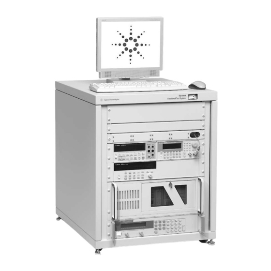
- Page 1 Agilent TS-5410 Compact Functional Test System Site Preparation and Installation Guide Agilent Technologies...
- Page 2 Notices © Agilent Technologies, Inc. 2003, 2004 Manual Part Number computer software” as defined in FAR 52.227-19 (June 1987) or any equivalent No part of this manual may be reproduced E2230-90010 agency regulation or contract clause. Use, in any form or by any means (including...
- Page 3 Safety Summary The following general safety precautions must be observed WARNING: DO NOT REMOVE during all phases of operation of ANY SYSTEM COVER this system. Failure to comply Operating personnel must not with these precautions or with remove system covers. Component specific warnings elsewhere in replacement and internal this manual violates safety...
- Page 4 Ground the System ASSURE THE EQUIPMENT UNDER TEST HAS To minimize shock hazard, the ADEQUATE INSULATION system chassis must have a BETWEEN THE CABLE hard-wired connection to an CONNECTIONS AND ANY electrical protective earth OPERATOR-ACCESSIBLE ground. The system must also be PARTS (DOORS, COVERS, connected to the ac power mains PANELS, SHIELDS, CASES,...
- Page 5 Table 1 Safety Symbols and Markings Safety symbols Warning: risk of electric shock. Caution: refer to accompanying documents. Alternating current. Both direct and alternating current. Earth (ground) terminal Protective earth (ground) terminal Frame or chassis terminal Terminal is at earth potential. Used for measurement and control circuits designed to be operated with one terminal at earth potential.
- Page 6 Measurement. Select your personnel. Contact your country from the drop-down customer engineer through your menus. The Web page that local Agilent Technologies appears next has contact Service Center. information specific for your country. Agilent on the Web...
- Page 7 Doc Placeholder Page...
-
Page 9: Table Of Contents
Contents Chapter 1 Site Preparation ......................11 System Intended Use ....................11 Rack Layout........................ 12 Ramp Requirements ..................13 Hallway and Door Width Requirements ............13 If the system cannot be moved in the crate ........... 13 System Requirements ....................14 Environmental Requirements .................. - Page 10 Contents...
-
Page 11: Site Preparation
Chapter 1 Site Preparation This chapter describes how to prepare your site for installation of the Agilent E22xxA Automotive Functional Test System. Site preparation information includes: • System Intended Use....... page 11 •... -
Page 12: Rack Layout
Rack Layout Figure 1-1 shows the system rack layout and rack dimensions. DC Fan Assy Load Box, Other PC Interconnect 33220A ARB/FG 33220A Arb & Other 34401A DVM 53131A 34401A DMM & 53131A Counter 3499A/B Switch/ Control Mainframe 3499A Switch Unit Serial Industrial PC 66XXA PS... -
Page 13: Ramp Requirements
Table 1-1. E22xxA Functional Test System Rack Specifications Size Dimension Height Width Depth 0.75m Exterior 740mm (29.1in) 600mm (23.6in) Outside of rack: 750mm (29.5in) 15 RU Including Express Connect, PC and Power Supply overhangs: 850mm (33.46in) *The approximate weight of a fully-loaded system is 112 kilograms (248 pounds) excluding the pallet and shipping crate. -
Page 14: System Requirements
System Requirements This section provides additional specifications for installing the Agilent E22xxA Test System. This information will be useful for initial site preparation, as well as for later reference if it becomes necessary to move the system to a different location. Anti-Static Static electricity is destructive to your production process and your Agilent E22xxA Test System. -
Page 15: Environmental Requirements
Environmental Requirements The air quality, temperature and humidity requirements for the system are described below. Air Quality As a rule, good air quality is as important for the reliability of your test system as it is for your production process. The presence of airborne contaminants at the site will contribute to system degradation, resulting in lower reliability and higher operating costs. -
Page 16: Cooling Requirements
Temperature The Agilent E22xxA Test System is designed to operate in the range from 5° C to 40° C (41° F to 104° F). Requirements Cooling Requirements As an option to the system, the system rack can be equipped with three extractor fans which draw air through the rack and exhaust it through the top rear of the rack. -
Page 17: The Site Plan Drawing
1 meter (3.3 feet) of space behind the system for service. The 0.75 meter rack is designed to fit under many production lines. Rack height is 740 mm (29.1 in.) Agilent Technologies Instrument and Service Automotive Functional Operator Area*... -
Page 18: Ac Power Requirements
AC Power Requirements Agilent E22xxA Automotive Functional Test Systems are equipped with a Filtered Power Strip that distributes AC Mains power to the various system equipment. Figure 2-3 shows the location of the Filtered Power Strip. The standard system is configured for 230-240 VAC, single-phase, 50/60 Hz. The system can be configured for other single-phase voltages by contacting Agilent service personnel. -
Page 19: Alternate Disconnect Recommendation
Alternate Disconnect Recommendation The ON/OFF switch on the front of the system DOES NOT remove power from the rack. Mains Disconnect A mains disconnect for emergency purposes can be as simple as unplugging the power cord from the power source receptacle. The receptacle and power cord plug must be easily accessible to use this method for emergency power shut-down. - Page 20 20 Site Preparation Chapter 1...
-
Page 21: Test System Installation
Chapter 2 Test System Installation This chapter describes how to ground the system, connect power to the system, make PC and peripheral connections and how to backup the system software. Chapter contents are: • Grounding and Connecting Power to the System ..page 22 •... -
Page 22: Grounding And Connecting Power To The System
Grounding and Connecting Power to the System Agilent E22xxA Automotive Functional Test Systems are equipped with a Filtered Power Strip that distributes AC Mains power to the various system equipment.The system is delivered with a mating power connector for the system appliance inlet. - Page 23 Protective Earth connection at the AC source where the system AC power cord is connected Earth (ground) terminal T oothed Toothed System Rack Washers Washers Wire Lug Wire Lug Bare Wire or Green Wire with Yellow Stripe Figure 2-1. Safety Ground Connections 3.
- Page 24 Strain Relief Power Cord Wire Colors: Blue = Neutral Brown - Line Green/Yellow = Ground Typical Power Plug (not supplied) Figure 2-3. Unterminated Power Cord (not supplied with all systems) Note The power cord and wall outlet connector selected must conform to the requirements of the country where the system will be installed.All electrical connections must be done by a qualified electrician 4.
-
Page 25: Pc And Peripheral Connections
lower rear of the test stand. DC Fan Assembly Mass Connect Engenious Engenious Connect Power Cord Here Power Strip REAR Figure 2-4. Filtered Power Strip/Cord Location 6. Plug-In the power cord to the power receptacle. Perform the following procedure “PC and Peripheral Connections” before turning on the system power switch. - Page 26 Cable Strain Cable Strain Relief Block Relief Block COM 1 KEYBOARD MOUSE MONITOR GPIB COM 2 Hole for External GPIB COM 1, Monitor Keyboard Mouse Routing Wires Connector Not Used Figure 2-5. PC and GPIB Connector Panel 2. Connect the monitor’s power cord to the receptacle on the Filtered Power Strip located in the bottom rear of the rack (Figure 2-6).
-
Page 27: Power Strip Breakers
Power Strip Breakers The Filtered Power Strip contains two 15A breakers, one on Line, one on Neutral (Figure 2-7). When a breaker opens (trips), a red mark can be seen on the breaker switch. Press the breaker button to reset. 15A Circuit Breakers Figure 2-7. -
Page 28: Getting Started
Getting Started The Agilent TestExec SL software is pre-installed on your PC controller’s hard drive. Agilent TestExec SL allows you to create testplans to control instruments and switching. Start TestExec SL from this icon in the PC desktop: You can also run TestExec SL by clicking: Start | Programs | Agilent TestExec SL 5.1 | TestExec SL 5.1 Getting Started The TS-5400 Online Help contains getting started examples for E22xxA... -
Page 29: Index
Index Access, for moving IEC320/C19 connector Air Quality Requirements If the system cannot be moved in the crate Alternate Disconnect Recommendation Altitude Anti-Static precautions Keyboard Backing Up the System Image Layout of the System Circuit breakers, Power Strip COM1, COM2 Mains Disconnect Connecting ground Monitor... - Page 30 Safety Ground Structure Side view, rack Site plan Static, precautions System Power Options System Weight Temperature Requirements Top view, rack Typical Power Plug Connections Typical test system layout (overhead view Viscid Contaminants Weight 30 Index...