Advertisement
Quick Links
PROPER USE GUIDELINES
Cumulative trauma disorders can result from the prolonged use of manually powered hand tools. Hand tools are intended for occasional
use and low-volume applications. A wide selection of powered application equipment is available for extended-use production operations.
© 2022 TE Connectivity Ltd. family of companies.
All Rights Reserved.
TE Connectivity, TE connectivity (logo), and TE (logo) are trademarks. Other logos, product, and/or company names may be trademarks of their respective owners.
PIDG™ PEEK STRATO-THERM™
Terminal Crimping Tools
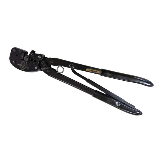
Figure 1: PIDG PEEK STRATO-THERM terminal crimping tool
Stationary crimping dies (anvils)
1
Locator
2
Movable crimping dies (indenters)
3
Insulation crimping adjustment pin
4
Ratchet control
5
304.8 mm [12.0 in.] (approximate)
6
76.2 mm [3.0 in.] (approximate)
7
PRODUCT INFORMATION 1-800-522-6752
408-10040
This controlled document is subject to change.
For latest revision and Regional Customer Service,
visit our website at www.te.com.
Instruction Sheet
9 SEP 2022 Rev G
1 of 12
Advertisement

Subscribe to Our Youtube Channel
Related Manuals for TE Connectivity PIDG PEEK STRATO-THERM


Summary of Contents for TE Connectivity PIDG PEEK STRATO-THERM
- Page 1 1 of 12 For latest revision and Regional Customer Service, All Rights Reserved. visit our website at www.te.com. TE Connectivity, TE connectivity (logo), and TE (logo) are trademarks. Other logos, product, and/or company names may be trademarks of their respective owners.
- Page 2 1. INTRODUCTION This instruction sheet covers hand crimping tools 576778, 576779, 576780, 576781, 576782, 576783, and 576784, which are used to crimp PIDG PEEK STRATO-THERM Terminals to the wire sizes listed in Table 1. Table 1: Crimping specifications Terminal color code...
- Page 3 408-10040 3. CRIMPING NOTE Refer to section 5 for information on insulation crimp adjustment. 1. Verify that the terminal insulation color code matches the tool handle color. 2. Select a wire of the correct size and insulation diameter for the terminal (see Table 1). Do not use wire with nicked or missing conductors.
- Page 4 408-10040 4. INSPECTING THE CRIMP Inspect crimped terminals by checking the features shown in Figure 3. Poor crimps (Figure 4) can be avoided by carefully following the procedures provided in section 3, and by following the tool maintenance procedures provided in section 6. Figure 3: Features of a good crimp Insulation barrel is in firm contact with wire insulation.
- Page 5 408-10040 5. ADJUSTING THE INSULATION CRIMP The insulation crimping section of the hand tool has an adjustment pin that controls the tightness of the crimp. This pin has three positions (Figure 5). Figure 5: Insulation crimp adjustment pin Tight Medium Loose To adjust the crimp tightness, complete the following steps.
-
Page 6: Maintenance And Inspection
408-10040 6. MAINTENANCE AND INSPECTION The hand tool is inspected before being shipped. Inspect it immediately upon arrival to ensure that it was not damaged during shipment. 6.1. Daily maintenance Make each operator of the power unit aware of, and responsible for, the following daily maintenance requirements: ... - Page 7 408-10040 6.4. Crimping die closure inspection Each tool is inspected for proper die closure before shipment. However, inspection of die closure for excessive wear is required periodically. This inspection requires the use of plug gages conforming to the dimensions shown in Table 3 and Table 4. Figure 6: Recommended plug gage design for wire barrel section of crimping chamber GO dimension NO GO dimension...
- Page 8 408-10040 Figure 7: Recommended plug gage design for insulation barrel section of crimping chamber Width GO dimension NO GO dimension 6.35 [.250] minimum (typical) Die closure configuration Table 4: Plug gage dimensions for insulation barrel crimping chamber Hand tool NO GO Width (W) 576778 0.813-0.820 [.0320-.0323]...
- Page 9 408-10040 To gage die closure, complete the following steps. 1. Remove traces of oil or dirt from the crimping chamber and plug gage. 2. Close the tool handles until the wire barrel dies are bottomed. Do not apply additional pressure to the tool handles.
-
Page 10: Replacement And Repair
408-10040 1. Insert the insulation crimping adjustment pin in position 1 (Figure 9). 2. With the crimping dies bottomed, check the insulation barrel section of the crimping chamber (Figure 9) as described in steps 4 and 5. If the crimping chamber conforms to the gage inspection, the tool is considered dimensionally correct. - Page 11 Shop TE link at the top of the page. Call 800-522-6752. Write to: CUSTOMER SERVICE (038-035) TE CONNECTIVITY CORPORATION PO BOX 3608 HARRISBURG PA 17105-3608 For customer repair services, call 800-522-6752. Figure 10: Replaceable parts Table 5: Part numbers...
-
Page 12: Revision Summary
408-10040 8. REVISION SUMMARY Revisions to this instruction sheet include: Reformatted to current standard for instruction sheets Updated handle colors in Table 1 12 of 12 Rev G...
Need help?
Do you have a question about the PIDG PEEK STRATO-THERM and is the answer not in the manual?
Questions and answers