Table of Contents
Advertisement
Quick Links
1. INTRODUCTION
The PDT-48-00 is a Pneumatic DEUTSCH Tool version of the
The PDT-48-00 is for production crimps.
The HDT-48-00 is for field repairs only.
NOTE
Dimensions in this instruction sheet are in millimeters with [inches in brackets]. Figures are for reference only and are not
drawn to scale.
Read these instructions thoroughly before crimping connectors.
© 2021 TE Connectivity Ltd. family of companies.
All Rights Reserved.
TE Connectivity, TE connectivity (logo), and TE (logo) are trademarks. Other logos, product, and/or company names may be trademarks of their respective owners.
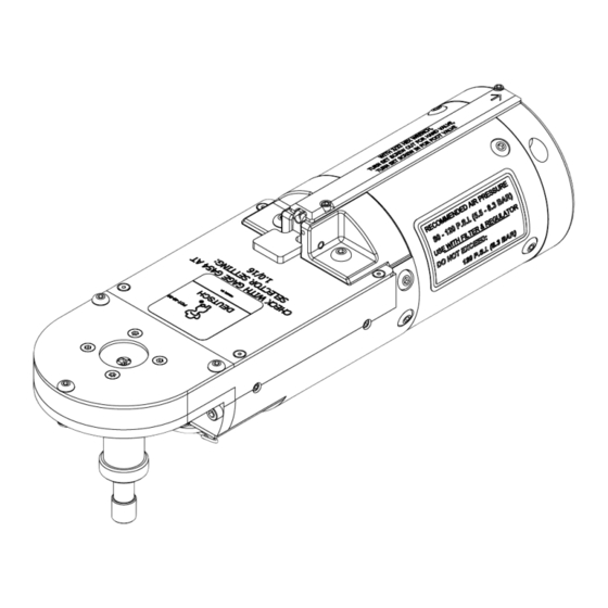
DEUTSCH Field Maintenance
Crimp Tool PDT-48-00
Figure 1: DEUTSCH Field Maintenance Crimp Tool PDT-48-00
PRODUCT INFORMATION 1-800-522-6752
HDT-48-00
(Hand DEUTSCH Tool).
This controlled document is subject to change.
For latest revision and Regional Customer Service,
visit our website at www.te.com.
Instruction Sheet
408-35208
Rev B
22 JUN 2021
1 of 7
Advertisement
Table of Contents

Related Manuals for TE Connectivity PDT-48-00


Summary of Contents for TE Connectivity PDT-48-00
- Page 1 1 of 7 For latest revision and Regional Customer Service, All Rights Reserved. visit our website at www.te.com. TE Connectivity, TE connectivity (logo), and TE (logo) are trademarks. Other logos, product, and/or company names may be trademarks of their respective owners.
- Page 2 408-35208 2. INSTALLATION 1. Use hardware to secure the base of the bench mount. This reduces the risk of damage from the tool falling onto the operator or the floor. 2. Adjust the bench mount for efficiency and ergonomics. a. Loosen by rotating the knob lever. b.
- Page 3 408-35208 3. CRIMPING WITH TOOL PDT-48-00 3.1. Wire selection Use Envelope Drawing PDT-48-00 for all wire/contact combinations. Table 1 simplifies popular sizes. NOTE The dial position is normally the same as the wire size (see Envelope Drawing for exceptions). Table 1: Wire sizes...
- Page 4 408-35208 3.3. Adjusting the tool 1. Cycle the tool to open the indenters. 2. Remove the locking clip (Figure 4). 3. Raise and rotate the dial (Figure 4) to select a wire size. Minimum 22 AWG [0.35 mm²] Maximum 12 AWG [3.00 mm²] NOTE The tool must be open prior to selecting a wire size.
- Page 5 408-35208 5. Loosen the locking ring (Figure 5). 6. Adjust the contact depth locator (Figure 5) to produce crimps as shown in Figure 3 by performing test crimps using the procedure described in section 1.4. 7. Tighten the locking ring. Figure 5: Locator and locking ring Locking ring Contact depth locator...
- Page 6 408-35208 4. MAINTENANCE AND INSPECTION 4.1. Maintenance Clean tool and remove debris regularly. Check for missing or loose hardware. Do not immerse tool in cleaners. Vacuum or wipe clean. Do not spray oil into tool to lubricate. Use in-line lubricator. ...
- Page 7 Shop TE link at the top of the page. Call 800-522-6752. Write to: CUSTOMER SERVICE (038-035) TE CONNECTIVITY CORPORATION PO BOX 3608 HARRISBURG PA 17105-3608 For customer repair services, call 800-522-6752. 6. REVISION SUMMARY Revisions to this instruction sheet include: Replaced Figure 1 with a more accurate drawing.
Need help?
Do you have a question about the PDT-48-00 and is the answer not in the manual?
Questions and answers