Table of Contents
Advertisement
Quick Links
Advertisement
Table of Contents

Related Manuals for Ametek 3330


Summary of Contents for Ametek 3330
- Page 1 OPERATION MANUAL Model 3330 Inline Viscometer Rev B – August 2022 P/N: 3330-OM S/N: ____________ 2001 N. Indianwood Ave. Broken Arrow, Oklahoma 74012 U.S.A. Telephone: 918-250-7200 Fax: 918-459-0165 E-mail: chandler@chandlereng.com Website: http://www.chandlereng.com...
- Page 2 This publication contains the following trademarks and/or registered trademarks for AMETEK and CHANDLER ENGINEERING. These trademarks or registered trademarks and stylized logos are all owned by AMETEK, Inc. All other company, product and service names and logos are trademarks or...
-
Page 3: Table Of Contents
TABLE OF CONTENTS Table of Contents General Information ............... P-1 Description ..........................P-1 Features and Benefits ......................P-1 Specifications ......................... P-2 Safety Requirements ......................P-3 Where to Find Help ........................ P-3 Section 1 – Installation ............1-1 Unpacking the Instrument ...................... 1-1 Utilities Required ........................ -
Page 5: General Information
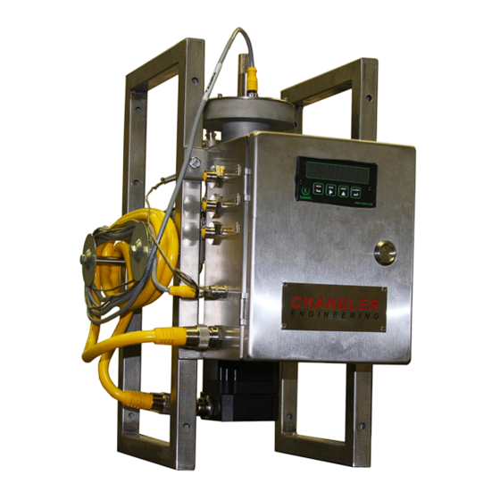
PREFACE General Information Description The Chandler Engineering Inline (Flow-Thru) Viscometer is a low pressure couette (cup/bob) viscometer for real time measurement of oilfield fluids during treatments. The instrument is connected in a sample line from the clean fluid delivery line. The viscometer measures viscosity at the standard 511 sec using the API standard R1 rotor, B1 bob, and F1 spring. -
Page 6: Specifications
PREFACE Specifications Pressure Range: 100 PSIG 32°F – 160°F Temperature Range: Flowrate: 1-5 gpm Viscosity Range: 0-160 cP Input Voltage: 12VDC Power: 6 A @ 12VDC 13.5” x 17” x 20” Dimensions: Net Weight: 56 lbs. (36 kg) Operating Speed: 300 RPM (511 sec ½”... -
Page 7: Safety Requirements
PREFACE Safety Requirements READ BEFORE ATTEMPTING OPERATION OF INSTRUMENT The Chandler Engineering Flow-Thru Viscometer is designed for operator safety. However, the instrument should be handled by personnel that have the appropriate safety training. To ensure safety: • Use appropriate Personal Protective Equipment such as safety glasses, latex gloves, etc. •... - Page 8 PREFACE This page is intentionally left blank.
-
Page 9: Section 1 - Installation
SECTION 1 – INSTALLATION Section 1 – Installation Unpacking the Instrument Remove the instrument from the packing crate carefully. The unit comes fully equipped with all the necessary components and ordered spare parts. Make sure that no parts are lost when discarding the packing materials. -
Page 10: Instrument Preparation
SECTION 1 – INSTALLATION Instrument Preparation 1. The viscometer is configured for portable or permanent installation. 2. The electronics enclosure is provided with 6 feet of instrument cable for remote mounting the operator interface in a more convenient location. 3. The instrument is provided with 2, ½” NPT threads for fluid connections. Connect the fluid delivery line from a clean fluid pressure source (such as the clean side blender centrifugal) to the lower viscometer port (or the filter system if equipped). -
Page 11: Section 2 - Operating Instructions
SECTION 2 – OPERATING INSTRUCTIONS Section 2 – Operating Instructions Test Preparation 1. Locate the Instrument on a level surface and make all fluid and power connections. 2. Turn the instrument ON (Green LED will be on). Note: Turning ON the instrument power will automatically zero the encoder. Therefore, the fluid input valve should be closed and no fluid should be flowing through the instrument. - Page 12 SECTION 2 – OPERATING INSTRUCTIONS 5. Carefully wipe dry the inside of the viscometer and the bob. 6. Reinstall measurement head onto viscometer.
-
Page 13: Section 3 - Maintenance
SECTION 3 – MAINTENANCE Section 3 - Maintenance Cleaning 1. Drain all fluid from the viscometer. 2. For good measurement practice, the viscometer should be hand cleaned periodically to remove fluid contamination. First, disconnect the encoder cable and unthread the large coupling nut to remove the measurement head. - Page 14 SECTION 3 – MAINTENANCE 5. Unthread the retaining nut and pull bob assembly out of measurement head. The bob assembly is held magnetically. Caution: Do not place the bob assembly near magnetic materials because of the strong magnets. 6. Clean and wipe any residue from the bob assembly. Be careful not to scratch the bob or shaft as this will cause measurement error.
-
Page 15: Calibration
SECTION 3 – MAINTENANCE 9. After cleaning rotor assembly, reinstall into viscometer using threaded nut. 10. Reinstall measurement head onto viscometer and connect encoder cable. Calibration Checking Calibration 1. Calibration should be checked prior to every use with a known clean calibration fluid, preferably, use a 100cP calibration oil. - Page 16 SECTION 3 – MAINTENANCE 9. Loosen the set screws holding the spring mandrel. 10. Turn the mandrel clockwise to decrease viscosity and counterclockwise to increase viscosity. 11. Tighten set screws (Note the spring assembly may need to be turned counterclockwise by hand to position the encoder against the zero stop prior to tightening.
-
Page 17: Torsion Spring Assembly
SECTION 3 – MAINTENANCE Torsion Spring Assembly The Flow-Thru Viscometer uses a standard F1 spring assembly. Replacement of Spring Assembly 1. Unthread top cap and loosen set screws at the top of the brass spring clamp. 2. Remove screws from spring housing and remove spring housing. 3. -
Page 18: Encoder Assembly
SECTION 3 – MAINTENANCE Encoder Assembly Replacement of the Encoder/Bearings 1. Remove screws at the top of the measurement head. Carefully, remove the encoder/spring assembly from the measurement head. The encoder/spring assembly is sealed with an O-ring. 2. With the encoder mechanism exposed, the assembly must be handled carefully to avoid damage to the components. - Page 19 SECTION 3 – MAINTENANCE 4. Unthread top cap and loosen set screws at top of spring assembly. 5. Remove screws from spring housing and remove spring housing. 6. Loosen set screws along the bottom of the spring holder and remove from shaft. 7.
- Page 20 SECTION 3 – MAINTENANCE 9. The encoder can be removed from the mag drive shaft by loosening the 2 screws. 10. Reassemble and recalibrate.
-
Page 21: Rotor Assembly
SECTION 3 – MAINTENANCE Rotor Assembly Replacement of Rotor Seal/Bearings 1. First unthread the large coupling nut for the motor. 2. Remove two screws which attach the rotor to the shaft. 3. Remove screws holder motor flange to the bearing housing. - Page 22 SECTION 3 – MAINTENANCE 3-10 4. Unthread bearing retainer and remove shaft and bearing assembly. Remove shaft seal. 5. Inspect bearings and seal and replace, if required. Reassemble.
-
Page 23: Bob Assembly
SECTION 3 – MAINTENANCE 3-11 Bob Assembly Replacement of Bob Shaft Bearings 1. The bob shaft runs in two glass journal bearings. One is located at each end of the bob shaft. Carefully remove the measurement head. Note: The measurement head has an O-ring seal and will be tight during removal. 2. -
Page 24: Maintenance Schedule
SECTION 3 – MAINTENANCE 3-12 6. Remove screws at the top of the measurement head. Carefully, remove the encoder/spring assembly from the measurement head. The encoder/spring assembly is sealed with an O-ring. 7. Remove the threaded retaining nut in the top of the measurement head housing. 8. -
Page 25: Section 4 - Troubleshooting Guide
SECTION 4 – TROUBLESHOOTING GUIDE Section 4 – Troubleshooting Guide Problem Solution • Check utility circuit. Instrument does not operate when • Check the fuses. power switch is ON. • Bad 12/24VDC converter. • Check the O-ring at the rotor housing. Fluid leak at rotor nut. - Page 26 SECTION 4 – TROUBLESHOOTING GUIDE This page is intentionally left blank.
-
Page 27: Section 5 - Replacement Parts
Part Number Description 103823 Filter Assembly, Field Viscometer 104167 PH Probe Assy, Signet Inline 104213 Hose Kit,3/4",Inline Viscometer 188-07566 Screw,Set,6-32 X 0.5,Dog 3330-0010 Viscometer Assembly 3330-0011 Rotor Assy, Visc, Flow-Thru 3330-0012 Head Assembly 3330-0013 Encoder/Spring Mechanism 3330-0017 Mag Drive, Outer... - Page 28 SECTION 5 – REPLACEMENT PARTS This page is intentionally left blank.
-
Page 29: Section 6 - Drawings And Schematics
SECTION 6 – DRAWINGS AND SCHEMATICS Section 6 - Drawings and Schematics Drawing Number Description 3330 Viscometer System 3330-0010 Viscometer Assembly 3330-0011 Rotor Assembly 3330-0012 Head Assembly 3330-0013 Encoder/Spring Assembly 3330-0030 Electronics Assembly 3330-0031 Wiring Diagram... - Page 30 SECTION 6 – DRAWINGS AND SCHEMATICS This page is intentionally left blank.
- Page 31 APPROVED NOTES: 10/30/2013 ECN T5582; PRODUCT LAUNCH APPLY TEFLON TAPE TO PIPE THREADS. ECN T6887; ADD REF DOCS, ITEM 13,14,15 10/15/2015 COMPLETE WIRING PER DRAWING 3330-0031. ECN T9286; VAVE 7/28/2021 ECN T9419; VAVE 4/18/2022 ECN T9464; REMOVE CABLE C15893 7/25/2022...
- Page 32 FORM EXCEPT AS EXPRESSLY AUTHORIZED BY THE 3 PLC 0.005 ANGL OWNER IS FORBIDDEN. THE HOLDER AGREES TO TYPE: PN: 3330-0010 REV A SIZE D RETURN THE DOCUMENT TO THE OWNER ON SURFACE FINISH 63 RMS DEMAND. COPYRIGHT BY CHANDLER ENGINEERING...
- Page 33 FORM EXCEPT AS EXPRESSLY AUTHORIZED BY THE 3 PLC 0.005 ANGL OWNER IS FORBIDDEN. THE HOLDER AGREES TO TYPE: PN: 3330-0011 REV A SIZE B SURFACE FINISH 63 RMS RETURN THE DOCUMENT TO THE OWNER ON DEMAND. COPYRIGHT BY CHANDLER ENGINEERING...
- Page 34 FORM EXCEPT AS EXPRESSLY AUTHORIZED BY THE 3 PLC 0.005 ANGL OWNER IS FORBIDDEN. THE HOLDER AGREES TO TYPE: PN: 3330-0012 REV A SIZE B SURFACE FINISH 63 RMS RETURN THE DOCUMENT TO THE OWNER ON DEMAND. COPYRIGHT BY CHANDLER ENGINEERING...
- Page 35 ASSEMBLE SPRING HOLDER TO SPRING ASSEMBLY AND MAG DRIVE SHAFT USING SET SCREWS. INSTALL SPRING HOUSING AND SPRING CLAMP. INSTALL OPTICAL ENCODER. INSTALL CONNECTOR AND ROUTE WIRES AS SHOWN. FOLLOW CALIBRATION PROCEDURE 3330-TP TO SET FINAL POSITION OF SPRING. INSTALL O-RING AND SPRING HOUSING CAP. CABLE DETAIL...
- Page 36 ATTACH TO PANEL WITH RIVETS 10,43,44 ADD NOTES 4-8, DEL ITEM 32,36,42 ADD ITEM 12/4/13 LEAVE 5 FT FREE CABLE LENGTH MINIMUM. REFERENCE 3330-0031 FOR WIRING DIAGRAM. ECN T5732; REPLACED ITEM 35, ADD ITEM 47-51 1/24/2014 ECN T9286; REMOVE TEMP CONNECTOR 7/28/2021 ECN T9463;...
- Page 38 cut out postcards on dotted lines Please Send Us Your Comments on This Manual Model Number ____________________________ Serial Number __________________________ Printing Date of this manual (from the Title Page) ______________ Please circle a response for each of the following statements. Use: (1)= Strongly agree (2) =Agree (3) =Neutral, no opinion (4) =Disagree (5) =Strongly disagree a) The manual is well organized.
- Page 39 cut out postcards on dotted lines...
- Page 40 4903 W. Sam Houston Parkway, N., Suite A-400, Houston, TX 77041 2001 North Indianwood Avenue, Broken Arrow, OK 74012 Tel: +1 713-466-4900 Fax: +1 713-849-1924 Tel: +1 918-250-7200 Fax: +1 918-459-0165 e-mail: chandler.sales@ametek.com www.chandlereng.com Printed in the U.S.A. © 2008, by AMETEK, Inc. All rights reserved. XM808PDF (360000)
- Page 41 APPROVED NOTES: 10/30/2013 ECN T5582; PRODUCT LAUNCH APPLY TEFLON TAPE TO PIPE THREADS. ECN T6887; ADD REF DOCS, ITEM 13,14,15 10/15/2015 COMPLETE WIRING PER DRAWING 3330-0031. ECN T9286; VAVE 7/28/2021 ECN T9419; VAVE 4/18/2022 ECN T9464; REMOVE CABLE C15893 7/25/2022...
- Page 42 FORM EXCEPT AS EXPRESSLY AUTHORIZED BY THE 3 PLC 0.005 ANGL OWNER IS FORBIDDEN. THE HOLDER AGREES TO TYPE: PN: 3330-0010 REV A SIZE D RETURN THE DOCUMENT TO THE OWNER ON SURFACE FINISH 63 RMS DEMAND. COPYRIGHT BY CHANDLER ENGINEERING...
- Page 43 FORM EXCEPT AS EXPRESSLY AUTHORIZED BY THE 3 PLC 0.005 ANGL OWNER IS FORBIDDEN. THE HOLDER AGREES TO TYPE: PN: 3330-0011 REV A SIZE B SURFACE FINISH 63 RMS RETURN THE DOCUMENT TO THE OWNER ON DEMAND. COPYRIGHT BY CHANDLER ENGINEERING...
- Page 44 FORM EXCEPT AS EXPRESSLY AUTHORIZED BY THE 3 PLC 0.005 ANGL OWNER IS FORBIDDEN. THE HOLDER AGREES TO TYPE: PN: 3330-0012 REV A SIZE B SURFACE FINISH 63 RMS RETURN THE DOCUMENT TO THE OWNER ON DEMAND. COPYRIGHT BY CHANDLER ENGINEERING...
- Page 45 ASSEMBLE SPRING HOLDER TO SPRING ASSEMBLY AND MAG DRIVE SHAFT USING SET SCREWS. INSTALL SPRING HOUSING AND SPRING CLAMP. INSTALL OPTICAL ENCODER. INSTALL CONNECTOR AND ROUTE WIRES AS SHOWN. FOLLOW CALIBRATION PROCEDURE 3330-TP TO SET FINAL POSITION OF SPRING. INSTALL O-RING AND SPRING HOUSING CAP. CABLE DETAIL...
- Page 46 ATTACH TO PANEL WITH RIVETS 10,43,44 ADD NOTES 4-8, DEL ITEM 32,36,42 ADD ITEM 12/4/13 LEAVE 5 FT FREE CABLE LENGTH MINIMUM. REFERENCE 3330-0031 FOR WIRING DIAGRAM. ECN T5732; REPLACED ITEM 35, ADD ITEM 47-51 1/24/2014 ECN T9286; REMOVE TEMP CONNECTOR 7/28/2021 ECN T9463;...
- Page 47 S.O. NO. DWG NO. REV. the property of Chandler Engineering Company LLC. Reproduction or 3330-0031 dissemination in any form except as expressly authorized by the owner is CHECKED: forbidden. The holder agrees to return this document to the owner on 1 /31/13 demand.
- Page 48 cut out postcards on dotted lines Please Send Us Your Comments on This Manual Model Number ____________________________ Serial Number __________________________ Printing Date of this manual (from the Title Page) ______________ Please circle a response for each of the following statements. Use: (1)= Strongly agree (2) =Agree (3) =Neutral, no opinion (4) =Disagree (5) =Strongly disagree a) The manual is well organized.
- Page 49 cut out postcards on dotted lines...
- Page 50 4903 W. Sam Houston Parkway, N., Suite A-400, Houston, TX 77041 2001 North Indianwood Avenue, Broken Arrow, OK 74012 Tel: +1 713-466-4900 Fax: +1 713-849-1924 Tel: +1 918-250-7200 Fax: +1 918-459-0165 e-mail: chandler.sales@ametek.com www.chandlereng.com Printed in the U.S.A. © 2008, by AMETEK, Inc. All rights reserved. XM808PDF (360000)
Need help?
Do you have a question about the 3330 and is the answer not in the manual?
Questions and answers