Table of Contents
Advertisement
Advertisement
Table of Contents

Related Manuals for Kamstrup flowIQ 3100 Series


Summary of Contents for Kamstrup flowIQ 3100 Series
- Page 1 Technical Description flowIQ® 3100 Water Meter...
- Page 2 TECHNICAL DESCRIPTION flowIQ® 3100 Kamstrup A/S • Technical Description • 5512-1242_N1_GB • 10.2019...
-
Page 3: Table Of Contents
12.1 Ultrasound with piezo ceramics ......................25 12.2 Principles ............................. 25 12.3 Transit time method ..........................26 12.4 Calculation of flow volume ........................28 12.5 Flow limits ............................28 Pressure loss ..........................29 Kamstrup A/S • Technical Description • 5512-1242_N1_GB • 10.2019... - Page 4 17.10 Verification mode ..........................53 17.11 Legal changes outside seal ........................54 Pulse Adapter for flowIQ® 3100 ....................56 18.1 Function .............................. 56 18.2 Application – environment ........................56 18.3 Lifetime ............................... 57 Kamstrup A/S • Technical Description • 5512-1242_N1_GB • 10.2019...
- Page 5 Communication (KMP) ........................ 64 21.1 Optical eye activation .......................... 64 METERTOOL for Kamstrup Water Meters ..................64 Troubleshooting .......................... 65 Disposal ............................65 24.1 Instructions for disposal ........................66 Documents ..........................67 Kamstrup A/S • Technical Description • 5512-1242_N1_GB • 10.2019...
- Page 6 TECHNICAL DESCRIPTION flowIQ® 3100 Kamstrup A/S • Technical Description • 5512-1242_N1_GB • 10.2019...
-
Page 7: General Description
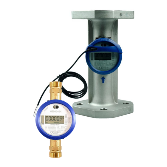
– a static cold water meter based on the ultrasonic principle. The cold water meter has been developed on the basis of Kamstrup's experience since 1991 with the development and production of static ultrasonic meters. -
Page 8: Front Plate
OIML R49 production year Meter size (Q Configuration (with Dynamic range information on display Software version resolution, encryption level etc.) Pressure stage and protection class Classifications Marking and approval Kamstrup A/S • Technical Description • 5512-1242_N1_GB • 10.2019... -
Page 9: Front Plate Dn 100
3100 TECHNICAL DESCRIPTION 1.2 Front plate DN 100 1.3 Front plate Wired M-Bus version Kamstrup A/S • Technical Description • 5512-1242_N1_GB • 10.2019... -
Page 10: Sealing
Directive (MID) based on OIML R49 with the with ‘FORCE Certification’ as notified body. OIML: ‘International Organization of Legal Metrology’) Please contact Kamstrup A/S for further details on national approvals and verification. Approval cert. no. DK-0200-MI001-017 (up to 63 m³/h) -
Page 11: Technical Data
(Mounted indoors in utility rooms and outdoors in meter pits) Avoid mounting in direct, prolonged sunlight. Storage temperature -25…60 °C (empty flow part) Weight see table in section ‘Meter size, connection, weight and dimensions’ Kamstrup A/S • Technical Description • 5512-1242_N1_GB • 10.2019... -
Page 12: Electrical Data
Reflectors Stainless steel, W.no. 1.4301, 1.4306, 1.4307, 1.4401, 1.4404 Strainer (filter) Polyarylethersulfone PES Meter Meter housing Polyphenylene sulphide – 40 % fibreglass Cover Glass Top ring (sealing) Polycarbonate (dyed – blue) Kamstrup A/S • Technical Description • 5512-1242_N1_GB • 10.2019... -
Page 13: Water Meter Sizes
Strainers can be ordered together with these types of threaded meters. According to OIML R49 maximum pressure loss at Q must not exceed 0.063 MPa (0.63 bar). At Q this results in a pressure loss of max. 0.1 MPa (1 bar). Kamstrup A/S • Technical Description • 5512-1242_N1_GB • 10.2019... -
Page 14: Type Overview
Then the configuration is completed. Finally, required accessories, if any, are selected, in the form of gaskets, non-return valve, strainer and standard couplings. Accessories are enclosed, separately, and to be mounted by the installer. Kamstrup A/S • Technical Description • 5512-1242_N1_GB • 10.2019... -
Page 15: Type Overview - Flowiq® 3100
Language on label etc. only for selected markets only for meters up to 63 m³/h(DN80) For DN100 only module 46 is available The type number of the meter cannot be changed after factory programming. Kamstrup A/S • Technical Description • 5512-1242_N1_GB • 10.2019... -
Page 16: Accessories
000000.001 m³ (only for DN100) Encryption level No encryption Utility encryption (only available for selected markets) Encryption with separately forwarded key Unless otherwise stated in the order, Kamstrup supplies the following: *Only for selected markets Kamstrup A/S • Technical Description • 5512-1242_N1_GB • 10.2019... -
Page 17: Communication
With the increased interval between the transmissions, the same high battery life is guaranteed. The table below summarizes and describes the data comprised by the Wireless M-Bus data package: Kamstrup A/S • Technical Description • 5512-1242_N1_GB • 10.2019... - Page 18 1.6 - 63 m³/h – Sigfox always in l/h Module 46: If encryption has been selected, when submitting the order, all variable data will be encrypted with ‘128 bits AES counter mode’ encryption. Kamstrup A/S recommends encryption. Kamstrup A/S • Technical Description • 5512-1242_N1_GB • 10.2019...
-
Page 19: Wired M-Bus Version Of Flowiq® 3100
Enhanced secondary addressing is supported by adding the meter’s serial number as M-Bus Fabrication Number to the secondary address. 7.2.10 Installation The meter is delivered with a 1.5 meter long standard polarity independent connection. Kamstrup A/S • Technical Description • 5512-1242_N1_GB • 10.2019... - Page 20 The daily flow and temperatures are the actual daily minimum, average or maximum values, logged from midnight until the present reading time. By ‘last month’ means the last fully calendar month. Kamstrup A/S • Technical Description • 5512-1242_N1_GB • 10.2019...
- Page 21 Rin / Cin 422 Ω/0.5 nF Max cable resistance 29 Ω/180 nF per pair Operational temperature 5 - 55°C Markings/approvals - EN 13757CE approval - MID Ordering See section ‘Type overview’ ‘Configuration’ Kamstrup A/S • Technical Description • 5512-1242_N1_GB • 10.2019...
-
Page 22: Optional Data Packages - Sigfox Installations
(C1, T1), and various reading intervals, by choosing a specific module. For each module there is an option of choosing between up to 10 different data packages. You must choose one data package. Choise of datapackages – see document no.: 5512-2336 Kamstrup A/S • Technical Description • 5512-1242_N1_GB • 10.2019... -
Page 23: Sigfox Modules
✓ ✓ Info codes ✓ ✓ Target volume V1 ✓ Max flow target* ✓ Min. flow target* the value is sent daily at target time. 10.2 Sequences R-package ✓ ✓ Sequence Kamstrup A/S • Technical Description • 5512-1242_N1_GB • 10.2019... -
Page 24: Measurements
(1.25 x Q OIML R49 requirements to water meters MPE (maximum permissible error range – according to OIML R49) Kamstrup water meter flowIQ® 3100 measuring accuracy R100 1.000 10.000 Flow l/h Kamstrup A/S • Technical Description • 5512-1242_N1_GB • 10.2019... -
Page 25: Temperature Measurement
Flow sensor manufacturers have been working on alternative techniques to replace the mechanical principle. Research and development at Kamstrup has proven that ultrasonic measuring is the most viable solution. Based on microprocessor technology and piezo ceramics, ultrasonic measuring is not only accurate but also reliable. -
Page 26: Transit Time Method
The area and the length which the signal travels in the sensor are well-known factors. The length which the signal travels can be expressed by , which can also be written as: where: is the measuring distance is the sound propagation velocity is the time Kamstrup A/S • Technical Description • 5512-1242_N1_GB • 10.2019... - Page 27 To minimize the influence from variations of the velocity of sound in water, the latter is measured via absolute time measurements between the two transducers. These measurements are subsequently in the built-in ASIC converted into the current velocity of sound, which is used in connection with flow calculations. Kamstrup A/S • Technical Description • 5512-1242_N1_GB • 10.2019...
-
Page 28: Calculation Of Flow Volume
(Q Please note, however, that high flow velocities > Q (Max flow) involve the risk of cavitation, especially at low static pressures below 0.2 MPa (2 bar) after the meter. Kamstrup A/S • Technical Description • 5512-1242_N1_GB • 10.2019... -
Page 29: Pressure Loss
G5/4B[R1] G5/4[R1] G5/4[R1] G5/4[R1] G11/2[R5/4] G5/4[R1] G11/2[R5/4] 10 & 16 G2B[R1½] 16 & 25 DN50 36.6 25 & 40 DN65 40 & 63 DN80 DN100 (2E) DN100 (3E) Pressure loss diagram Kamstrup A/S • Technical Description • 5512-1242_N1_GB • 10.2019... -
Page 30: Dimensioned Sketches
10 m³/h – G5/4B(R1) x 260 mm 6.3 m³/h – G1½B x 260 mm 10 m³/h – G1½B x 260 mm 10 m³/h – G2B(R1½) x 300 mm 16 m³/h – G2B(R1½) x 300 mm Kamstrup A/S • Technical Description • 5512-1242_N1_GB • 10.2019... - Page 31 40 m³/h – DN65 x 300 mm 40 m³/h – DN80 x 300 mm 63 m³/h – DN80 x 300 mm 2E + 3E 100 m³/h – DN100 x 360 mm Kamstrup A/S • Technical Description • 5512-1242_N1_GB • 10.2019...
-
Page 32: Dimensions
For M16 bolts (also see table) Water meter, Type L & W – 16 & 25 m 62.5 62.5 Water meter, Type M & Q – 25 & 40 m 27.7 27.7 Kamstrup A/S • Technical Description • 5512-1242_N1_GB • 10.2019... - Page 33 3100 TECHNICAL DESCRIPTION Water meter, Type N & X – 40 & 63 m 30.6 30.6 73.9 73.9 Water meter, Type 2E+ 3E – 100 m 83.2 83.2 Kamstrup A/S • Technical Description • 5512-1242_N1_GB • 10.2019...
-
Page 34: Meter Size, Connection, Weight And Dimensions
1.05 G1B (R¾)* 91.6 G5/4B (R1) 91.6 G5/4B (R1) 91.6 G5/4B(R1)* 91.6 G5/4B(R1)* 91.6 G1½B(R5/4)* 91.6 G2B(R1½)* 104.5 91.6 Flange DN50 DN65 12.0 DN80 14.2 DN100 16.2 DN100 19.7 Hot forged Kamstrup A/S • Technical Description • 5512-1242_N1_GB • 10.2019... -
Page 35: Installation
PN10 or PN16 connections are used. Kamstrup A/S recommends drinking water approved fibre gaskets for cold water installations. If a non-return valve is installed, it will usually be necessary to use 4 mm PE gaskets instead, to prevent the collar of the coupling from damaging the valve. - Page 36 In order to facilitate replacement of the meter, closing valves should be mounted on both sides of the meter. Under normal operating conditions no pipe strainer is required in front of the meter. Kamstrup A/S • Technical Description • 5512-1242_N1_GB • 10.2019...
-
Page 37: Installation Angle
In order to avoid formation of air bubbles or vapor dents in the meter (cavitation) – and to ensure correct measurement under all circumstances – the operating pressure in the pipe installation, immediately after the meter (the downstream), must always be minimum 0.2 MPa (2 bar). Kamstrup A/S • Technical Description • 5512-1242_N1_GB • 10.2019... -
Page 38: Reading And Data
Receiving the Wireless M-bus signal, which is emitted at intervals of 16 or 96 seconds, depending on the meter configuration, alternatively receiving the wired M-Bus datagram • Reading via the optical eye, e.g. by means of Kamstrup A/S’ wireless optical reading head, or optical reading head with USB connector. 16.2 Volume measurement The meter calculates water flow currently according to a fixed measuring cycle. -
Page 39: Data Function: Target Date
Logging the minimum flow is a valuable information when tracing excessive consumption from temporary leaks. Kamstrup A/S • Technical Description • 5512-1242_N1_GB • 10.2019... -
Page 40: Temperature Monitoring
During periods without water flow the weighted average cannot be calculated and then a code 128 is stored, indicating that there is no consumption. Measuring the water temperature is only valid for meter sizes 1.6, 2.5 and 4.0 m Kamstrup A/S • Technical Description • 5512-1242_N1_GB • 10.2019... -
Page 41: Display Functions
99,999.999. The table below shows an overview of modes and readings: Normal mode Verification mode V1HighRes Data register Unit Number of digits Decimals after point 0-1-2 or 3 Kamstrup A/S • Technical Description • 5512-1242_N1_GB • 10.2019... - Page 42 In normal mode they flash once a second. In verification mode they flash twice a second. Below you see the shift between the two dots: Kamstrup A/S • Technical Description • 5512-1242_N1_GB • 10.2019...
- Page 43 The Wireless M-Bus signal includes the LEAK code. If the LEAK code is active, or has been active within the latest 30 days, a time indicator with 7 time intervals will indicate how long the info code has been active. Kamstrup A/S • Technical Description • 5512-1242_N1_GB • 10.2019...
- Page 44 In order to avoid false alarms due to short-term air build-up in the meter, the info code DRY is not added to the relevant registers until it has been continuously active for 30 minutes. Kamstrup A/S • Technical Description • 5512-1242_N1_GB • 10.2019...
- Page 45 Info code – RADIO OFF (transport mode) This info code is active and flashes in the display when the water meter leaves Kamstrup A/S, and indicates, that the meter is still in ‘transport mode’ and that the built-in Wireless M-Bus radio transmitter has not yet been activated.
- Page 46 +/- 10 %. As long as no adjustments have been made, both the ‘A’ and the digit are inactive, and Kamstrup A/S does not add further adjustment marking to the meter. After the first adjustment, the ‘A’ activates and the digit shows the number of adjustments (1 to 9).
-
Page 47: Optical Eye
The meter is fitted with an optical eye that gives access to the meter's external interface, with which all the meter's data registers can be read. For instance data can be read using Kamstrup's optical reading head. The reading head includes a permanent magnet which switches on the optical eye. -
Page 48: Data Loggers
The loggers are static ones. Thus, the register types cannot be changed. The same applies to the logging intervals. When there is no more space in logger (EEPROM), the newest logging will overwrite the oldest log. Kamstrup A/S • Technical Description • 5512-1242_N1_GB • 10.2019... -
Page 49: Yearly, Monthly And Daily Loggers
For the following modules: 60, 61, 62, 63, 64, 65 and 99 the daily, monthly and yearly loggers are not accessible from the optical eye, which is why the values in the loggers will be cero (showing a ‘0’). Kamstrup A/S • Technical Description • 5512-1242_N1_GB • 10.2019... -
Page 50: Optional Register In Data Logger
If the meter for example is purchased with module 40, it can be reconfigured to match one of the other modules. In addition to this, the radio can be turned off when needed. Already during the ordering process the desired setting is taken into account. DataTool can be obtained from Kamstrup by sending an e-mail to service@kamstrup.com... -
Page 51: Hour Counter
The register size is 2 bytes, apportioned with 4 bits for info codes and 12 bits for the info code hour counters. The distribution is shown below – the numbering shows the bit position. Kamstrup A/S • Technical Description • 5512-1242_N1_GB • 10.2019... - Page 52 14396 has been read. The value is converted to binary digits, and leading zeroes are added to reach a total of 16 characters. This makes: 001 110 000 011 1100 Entering these digits into the above table makes: Kamstrup A/S • Technical Description • 5512-1242_N1_GB • 10.2019...
-
Page 53: Meter Modes (Settings)
When the meter switches to ‘verification mode’, the wireless M-Bus radio transmitter will be turned off. At the same time a time-out starts. When the time-out period has expired the meter switches back to normal mode. The time-out period is 9 hours. Kamstrup A/S • Technical Description • 5512-1242_N1_GB • 10.2019... -
Page 54: Legal Changes Outside Seal
The meter is initially verified from the factory. A new factory adjustment requires disassembling of the meter and can only be carried out by Kamstrup A/S. When the meter has been locked it is only possible to make a percentage correction of the flow curve at three individual points. This is called re-adjustment. - Page 55 3100 TECHNICAL DESCRIPTION Below, samples of: Re-verification label Label used at control testing (at meters not approved for re-verification) Kamstrup A/S • Technical Description • 5512-1242_N1_GB • 10.2019...
-
Page 56: Pulse Adapter For Flowiq® 3100
The Pulse Adapter can be used for flowIQ® 3100 – SW revision H1 and forward. *Not for wired version of flowIQ® 3100 18.2 Application – environment • Ambient temperature: 2 °C…55 °C • Storage temperature: -25 °C…60 °C • Protection class: IP65 Kamstrup A/S • Technical Description • 5512-1242_N1_GB • 10.2019... -
Page 57: Lifetime
3. Push the button on the PCB, which is placed under the cover (see figure below). As soon as the button is pushed, serial optical communication between Pulse Adapter and meter starts. Kamstrup A/S • Technical Description • 5512-1242_N1_GB • 10.2019... -
Page 58: Pull-Up
The acquisition unit must have built-in ’pull-up’ – shown in figure below – to ensure correct voltage level of the pulse. The pulse output is two-wired and must be connected as follows: Sketch for connection of Pulse Adapter Kamstrup A/S • Technical Description • 5512-1242_N1_GB • 10.2019... - Page 59 The connection marked ’-‘ must be connected to the receiver's GND level. The connection marked ‘+’ should be connected to a pull-up resistor of an appropriate size, so that the maximum limits, shown in the table above, are met. Kamstrup A/S • Technical Description • 5512-1242_N1_GB • 10.2019...
-
Page 60: Pulse Interface For Flowiq® 3100
[pulses/liter] 1.6 & 2.5 12.5 12.5 6.25 Pulse Supply: 3.5-30 VDC < 15 mA 3.125 Standby: < 0.2 mA 1.563 Pulse width: = 3.9ms 1.563 Frequency: Max frequency of 128 Hz Kamstrup A/S • Technical Description • 5512-1242_N1_GB • 10.2019... -
Page 61: Connection Pulse Interface
The connection of the 8-pole plug ‘J1’ is indicated in figures below/next page. 19.1.1 Connection with pulse receiver without supply. Here external supply for Pull-up is required Power supply Pulse receiver Kamstrup A/S • Technical Description • 5512-1242_N1_GB • 10.2019... - Page 62 TECHNICAL DESCRIPTION flowIQ® 3100 19.1.2 Connection of pulse receiver with supply Here the supply from the receiver can be used. Power supply Pulse receiver Kamstrup A/S • Technical Description • 5512-1242_N1_GB • 10.2019...
-
Page 63: Data Communication
Radio transmission has been interrupted if ‘RADIO OFF’ is displayed. RADIO OFF is activated at the end of the production process at Kamstrup A/S. The meter removes RADIO OFF automatically, when the volume register has counted water consumption for approx. 5 seconds. -
Page 64: Radio Disabled
Get further information and technical details on METERTOOL/LogView in document: 5512-1653_GB – ’Technical Description for METERTOOL & LogView’ Kamstrup A/S • Technical Description • 5512-1242_N1_GB • 10.2019... -
Page 65: Troubleshooting
24 Disposal Kamstrup A/S holds an environmental certification according to ISO 14001, and as part of our environment policy we use materials which can be recovered environmentally correct to the greatest possible extent. • Disposal by Kamstrup A/S Kamstrup A/S accepts worn-out meters for environmentally correct disposal according to previous agreement. -
Page 66: Instructions For Disposal
EPS-recovery Terephthalate) also used for food Please send any questions you may have regarding environmental matters to: Kamstrup A/S Att.: Quality and environmental dept. Fax: +45 89 93 10 01 info@kamstrup.com Kamstrup A/S • Technical Description • 5512-1242_N1_GB • 10.2019... -
Page 67: Documents
Data Sheet 5810-1168 5810-1169 5810-1170 5810-1171 Installation Guide 5512-1181 5512-1182 5512-1184 Accessories list 5810-1269 5810-1270 Technical description 5512-1700 Wireless M-Bus Technical Description for 5512-1680 5512-1653 5512-1679 5512-1681 METERTOOL/LogView 5512-2336 Communication Module Overview Kamstrup A/S • Technical Description • 5512-1242_N1_GB • 10.2019... - Page 68 TECHNICAL DESCRIPTION flowIQ® 3100 Kamstrup A/S Industrivej 28, Stilling DK-8660 Skanderborg TEL: +45 89 93 10 00 FAX: +45 89 93 10 01 info@kamstrup.com kamstrup.com Kamstrup A/S • Technical Description • 5512-1242_N1_GB • 10.2019...
Need help?
Do you have a question about the flowIQ 3100 Series and is the answer not in the manual?
Questions and answers