
Related Manuals for Kamstrup flowIQ 4200


Summary of Contents for Kamstrup flowIQ 4200
- Page 1 Installation guide flowIQ® 4200 - US Kamstrup Water Metering, LLC · 245 Hembree Park Drive, Ste. 110 · Roswell, GA 30076, USA · info-us@kamstrup.com...
-
Page 2: Table Of Contents
4.3.3 Installing the split flanges on the meter first 4.3.4 Installing the flange on the pipeline first 4.4 Installation angle 4.5 Straight inlet 4.6 Flow disturbance and flow cavitation 4.6.1 Service connection FCC Cautions ICES/ISED cautions Kamstrup A/S • 55123307_A1_EN-US_06.2022... -
Page 3: In General
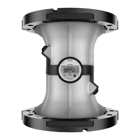
Installation guide flowIQ® 4200 1 In general Please read this guide carefully before installing Kamstrup water meters. flowIQ® 4200 meters are used for measuring potable water and all variants are built for submerged conditions. All meters have an arrow on the side of the meter body, indicating the correct flow direction through the meter. -
Page 4: Lids
- Lid: type no: 66-99-645 Kamstrup requires the installation of a lid if the meter – installed in the intended application – is: • Installed in public places where unauthorized persons may have access to the meter •... -
Page 5: Installation Requirements
– the operating pressure in the pipe installation must always be minimum: • 275 PSI – split flange meters – flowIQ® 4200 Note: Avoid installation where there is no option for back pressure Kamstrup A/S • 55123307_A1_EN-US_06.2022... -
Page 6: Flow Direction
A flowIQ® 4200 meter is delivered with separate coated split flanges in cast iron. Furthermore the 6” and 8” variants of the meter are delivered with spool pieces. Use only the original split flanges and spool pieces from Kamstrup combined with original fiber gaskets. Gaskets can be ordered separately. -
Page 7: Sediments In The Water
Installation guide flowIQ® 4200 4.1 Sediments in the water If the water contains sediments Kamstrup suggests to install the meter with the cup facing upwards. 4.2 ‘Spool piece installation (only applies to 6” and 8” meters) Spool pieces should be mounted on the pipeline flanges first to ensure flexible options in regards to split flange installation on either pipeline or meter. -
Page 8: Split Flange Installation
Tighten all flange bolts according to the described criss-cross pattern with the correct tightening torque. Repeat this procedure three times in total to ensure correct meter installation. Note! Criss-cross pattern to be repeated three times. Kamstrup A/S • 55123307_A1_EN-US_06.2022... -
Page 9: General Flange Features And Specifications
7/16” bolt from the opposite side to press and enlarge the gap between the flanges, thus creating space for the gasket. Lifting lugs The lifting lugs have two purposes: • Supporting safe conduct regarding meter installation when lifting • Fixating the split flanges on the meter Kamstrup A/S • 55123307_A1_EN-US_06.2022... -
Page 10: Criss-Cross Pattern
• Fixate the two split flanges together by using a ¼” bolt • Place the flange around the meter and close the flange by fixing a second ¼” bolt in the opposite side • Turn the meter upside down and install the other split flange Kamstrup A/S • 55123307_A1_EN-US_06.2022... -
Page 11: Installing The Flange On The Pipeline First
• Place the below part of the split flange on the below part of the pipeline flange by fixating the two lowest bolts first as shown in the figure below • Insert the gasket between the flange and the pipeline flange Kamstrup A/S • 55123307_A1_EN-US_06.2022... -
Page 12: Installation Angle
In order to facilitate replacement of the meter, closing valves should be mounted on both sides of the meter. Under normal operating conditions, a strainer is not required in front of the meter. Kamstrup A/S • 55123307_A1_EN-US_06.2022... -
Page 13: Fcc Cautions
- Increase the separation between the equipment and receiver. - Connect the equipment into an outlet on a circuit different from that to which the receiver is connected. - Consult the dealer or an experienced radio/TV technician for help. Kamstrup A/S • 55123307_A1_EN-US_06.2022... -
Page 14: Ices/Ised Cautions
25 cm spacing be provided between antenna(s) and all person’s body (excluding extremities of hands, wrist and feet) during wireless modes of operation. Must be installed to provide a separation distance of at least 25 cm from all persons. Kamstrup A/S • 55123307_A1_EN-US_06.2022... - Page 15 (à l’exclusion des extrémités des mains, des poignets et des pieds) pendant les modes de fonctionnement sans fil. Doit être installé de façon à respecter une distance de minimum 25 cm à toute personne. Kamstrup A/S • 55123307_A1_EN-US_06.2022...
- Page 16 Installation guide flowIQ® 4200 Kamstrup A/S • 55123307_A1_EN-US_06.2022...
Need help?
Do you have a question about the flowIQ 4200 and is the answer not in the manual?
Questions and answers