Table of Contents
Advertisement
Quick Links
SISTP1040-551-LRT Quick Start Guide
SISTP1040-551-LRT
Unmanaged Hardened Gigabit Ethernet PoE++ Switch
Quick Start Guide
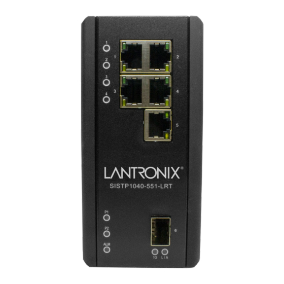
This switch is an unmanaged full Gigabit Ethernet hardened PoE++ switch that complies with IEEE
802.3bt, IEEE 802.3at and IEEE 802.3af. The switch has four 10/100/1000Base-T PoE++ ports, one
10/100/1000Base-T port and one 100/1000 dual speed SFP slot. It can deliver up to 90 Watts on
each PoE++ port simultaneously. The SISTP1040-551-LRT can be used to power PoE lighting, high
powered IP cameras and digital signage. It has redundant input power connections to ensure safe,
reliable operation in temperatures of -40°C to +75°C.
Note: If this equipment is used in a manner not specified by the manufacturer, the protection provided by the
equipment may be impaired. Note: See the full Install Guide for important Safety Warnings and Cautions,
Overview, Ordering Information, Features, Technical Specifications, Package Checklist, Safety Instructions,
Cautions and Warnings, Mounting, Front Panel and Top Panel, Ground Connection, Ethernet Interface
Connections, Power Connection, Alarm Relay Connection, DIP Switch Settings, LED Status Indicators, Power
Supply Information, Troubleshooting, Regulatory Agency Information, Warranty, and Contact information.
Package Checklist
Verify that the box contains one SISTP1040-551-LRT switch, two Wall-mount brackets, one
DIN-Rail Clip, four M4 Screws, one terminal block, this document, and a support postcard.
Note that a Power Supply is not included with the switch (sold separately).
An optional
second Power Supply can be ordered separately to provide dual power capability.
DIN-Rail Mounting
1. Screw the DIN-Rail bracket onto the switch with the bracket and screws provided. 2. Hook the unit over the
DIN rail. 3. Push the bottom of the unit towards the DIN Rail until it snaps into place. See the Install Guide.
Wall Mounting
1. Mark and prep holes in the wall surface for mounting. 2. Screw the wall-mount brackets onto the switch with
the M4 screws provided. 3. Screw the switch and wall mount brackets onto the wall (screws not provided).
See the Install Guide.
Front Panel and Top Panel
The front panel provides the LEDs and Ethernet interface connections (RJ45, Fiber/SFP).
The top panel contains the Power and Alarm connections, Ground screw, and DIP switch.
Ground Connection
The switch must be properly grounded for best system performance. This equipment
must be grounded with screw and wire (18 AWG min, green and yellow wires).
Ethernet Interface Connection (RJ45 Ethernet)
The switch provides two types of interfaces: electrical (RJ45) and optical (SFP). To connect
the Ethernet interface via RJ45: 1. Connect to a PC using a straight-through or crossover
Ethernet cable. 2. Connect the switch to an Ethernet device using UTP or STP Ethernet
cables. See the Install Guide for RJ-45 connector pin assignments and for PoE Deployment
in Environments A and B.
33840 Rev. A
https://www.lantronix.com/
Page 1 of 2
Advertisement
Table of Contents

Subscribe to Our Youtube Channel
Related Manuals for Lantronix SISTP1040-551-LRT


Summary of Contents for Lantronix SISTP1040-551-LRT
- Page 1 10/100/1000Base-T port and one 100/1000 dual speed SFP slot. It can deliver up to 90 Watts on each PoE++ port simultaneously. The SISTP1040-551-LRT can be used to power PoE lighting, high powered IP cameras and digital signage. It has redundant input power connections to ensure safe, reliable operation in temperatures of -40°C to +75°C.
- Page 2 Property: © 2021 Lantronix, Inc. All rights reserved. No part of the contents of this publication may be transmitted or reproduced in any form or by any means without the written permission of Lantronix. All other trademarks and trade names are the property of their respective holders.
Need help?
Do you have a question about the SISTP1040-551-LRT and is the answer not in the manual?
Questions and answers