Table of Contents
Advertisement
Quick Links
Advertisement
Table of Contents

Related Manuals for Lumel N20ZPLUS


Summary of Contents for Lumel N20ZPLUS
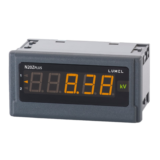
- Page 1 digital panel meter N20Z PLUS user’s manual...
-
Page 2: Table Of Contents
APPLICATION and DESIGN of the METER ..............2 METER SET ........................3 Basic requirements, operational safety ................3 Fitting ..........................3 4.1. Connection diagrams ....................4 Operation ..........................5 5.1. Display description ...................... 5 5.2. Messages after Switching the Supply on ..............5 5.3. -
Page 3: Application And Design Of The Meter
LED display which enables the presentation of measurements results in red, green or orange color The N20ZPLUS meter has a built-in RS-485 interface and the MODBUS RTU protocol provided, by means of which it is possible to configure the meter or read the measured values. -
Page 4: Meter Set
User’s Manual N20ZPLUS-09A METER SET Complete set of the Analyzer includes: - N20ZPLUS meter 1 pc. - clamps to fix the meter in the panel 4 pcs. Basic requirements, operational safety Meaning of the symbols used in this manual: Warning! Warning of potentially dangerous situations. -
Page 5: Connection Diagrams
(Fig. 2) Fig. 2: Meter fitting Fig. 3: Meter overall dimensions 4.1. Connection diagrams supply Fig. 4: Electrical connections of the N20ZPLUS meter for voltage and frequency measurements supply Fig. 5: Electrical connections of the N20ZPLUS meter for current measurements... -
Page 6: Operation
5.3. Configuration of the meter To configure the N20ZPLUS meter the user can use free eCon software available for download on the manufacturer's website (www.lumel.com.pl). The meter should be connected to a PC via a USB to RS-485 converter, e.g. PD10, and then in the E-Con program, the transmission parameters in accordance with those set in the meter should be selected. -
Page 7: Parameter Description
User’s Manual N20ZPLUS-09A 5.4. Parameter description 5.4.1. Display The display can be configured by changing the settings of the following parameters: display colors of the measured value. The display range is divided into three areas separated by threshold values KpL and KpH (respectively lower threshold KpL and upper threshold KpH of the change of the display color - Fig. - Page 8 User’s Manual N20ZPLUS-09A principle of "rolling window", i.e. the earliest measurement is discarded and the most recently measured one is put in its place. Measuring values outside the measurement range results in displaying the exceeding and starting to count correct measurements from the beginning.
-
Page 9: Alarm Parameters
Coefficients A and B are individual characteristics parameters. 5.4.3. Alarm parameters Two alarms are available in the N20ZPLUS meter. Both work independently and each of them has 6 operating modes: n-on, n-off, on, off, hon and hoff, which are shown in Figure 9. The alarm thresholds Aoff and Aon are set in the values of the measured value, taking into account the individual characteristics. -
Page 10: Communication Parameters
Other alarm types: hon - always enabled; hoff - always disabled. 5.4.4. Communication parameters The N20ZPLUS meter is equipped with an isolated RS-485 interface and the communication takes place via the Modbus RTU protocol. The following parameters are available to configure the correct communication: - address on the Modbus, can take values from the range 1 ... -
Page 11: Map Of Modbus Registers
8N2, 8E1, 8O1, 8N1 MAP OF MODBUS REGISTERS In N20ZPLUS meter the data is placed in 16- and 32-bit registers. Parameters and measured values of the meter are located in the address space of registers in a manner dependent on the type of the variable. Bits in 16-bit registers are numbered from the youngest to the oldest (b0-b15). - Page 12 User’s Manual N20ZPLUS-09A Table 3. Address Value type Description range 4000 - Integer Configuration of meter operation parameters (fixed-point 4023 (16 bits) parameters). Value placed in one 16-bit register. 7600 - Float Configuration of meter operation parameters (floating point 7609 (32 bits) parameters).
- Page 13 User’s Manual N20ZPLUS-09A 3 – off 4 – hon 5 – hoff 4008 Alarm 2 switching delay 0...120 4009 Enabling the individual characteristics. 0 – characteristics off Characteristics parameters placed in registers 7600 1 – characteristics on and 7601 4010 Measurement results averaging time (pt.
- Page 14 User’s Manual N20ZPLUS-09A 2 – 8O1 3 - 8N1 4023 Application of transmission parameters. 0 – do nothing 1 - apply changes Table 5. Addre Address Address Register Description Scope of type changes (2x16bit (2x16bit „3210”) „1032”) 7600 7000 6000 Parameter A of individual -19999…99999...
-
Page 15: Error Codes
User’s Manual N20ZPLUS-09A ERROR CODES After switching the meter on, error messages may appear. The causes of the errors are listed below. Exceeding the upper value of the programmed indication range. Exceeding the lower value of the programmed indication range. - Page 16 User’s Manual N20ZPLUS-09A Additional errors in rated operating conditions: - due to changes in ambient temperature (50 % of intrinsic error/10 K) Averaging time: voltage, current (programmable) min 0.5 s (default 1 s) frequency (non-programmable) Alarm outputs : OC output type (30 V, 20 mA), passive acc. to EN 62053-31 Serial interface RS-485, address 1..247...
- Page 17 User’s Manual N20ZPLUS-09A Safety requirements according to EN 61010-1: – insulation between circuits: basic, – installation category III (for 400 V version – category II), – degree of pollution 2, – maximum operating voltage relative to earth: - for supply circuit 300 V,...
-
Page 18: Ordering Codes
User’s Manual N20ZPLUS-09A ORDERING CODES Ordering code for N20ZPLUS panel meter Table 6 N20ZPLUS X X XX XX X X PANEL METER Input 100 V 250 V 400 V frequency 20...500 Hz Supply voltage 85...253 V a.c./d.c. 20..40 V a.c./20..60 V d.c. - Page 19 N20ZPLUS-09A rev. m km/h on request – After consultation with the manufacturer SAMPLE ORDER: N20ZPLUS-310100P0 means N20ZPlus meter with voltage input for the 400 V range, power supply 85..253 V a.c., Polish language version, version without additional requirements. Unit: "V".
- Page 20 LUMEL S.A. ul. słubicka 4, 65-127 Zielona góra, poland tel.: +48 68 45 75 100, fax +48 68 45 75 508 www.lumel.com.pl Technical support: tel.: (+48 68) 45 75 143, 45 75 141, 45 75 144, 45 75 140 e-mail: export@lumel.com.pl Export department: tel.: (+48 68) 45 75 130, 45 75 132...
Need help?
Do you have a question about the N20ZPLUS and is the answer not in the manual?
Questions and answers