Table of Contents
Advertisement
Quick Links
Advertisement
Table of Contents

Related Manuals for Lumel N21


Summary of Contents for Lumel N21
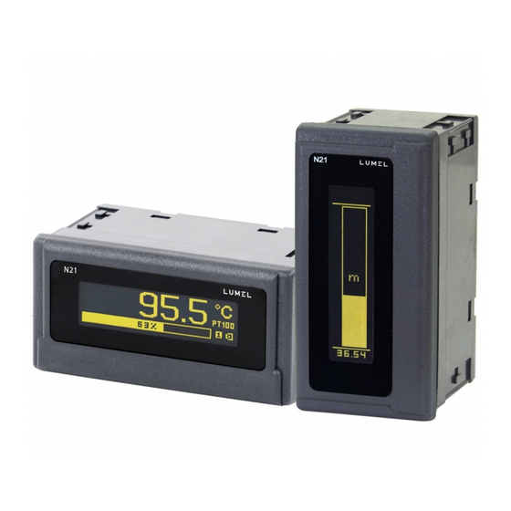
- Page 1 PANEL MOUNTED METER USER’S MANUAL...
-
Page 3: Table Of Contents
5.3.6 Editor of the measuring unit ..........23 6. CONFIGURATION INTERFACE ............ 25 6.1 USB Interface – list of parameters ......... 25 6.2 Map of N21 meter registers ..........25 7. ERROR CODES ..............32 8. SOFTWARE UPDATE .............. 34 9. -
Page 5: Application And Meter Design
Pt100 resistance thermometers. The readout field is an OLED graphic display with a resolution of 32x128 points. The eCon program is designed for the configuration of the N21 meter. The meter should be connected to a PC via a miniUSB connector located on the rear of the meter. -
Page 6: Meter Set
- seal ............1 pc - user’s manual ..........1 pc - guarantee card .......... 1 pc Accessories: For the N21 meter you can order: – USB CABLE A/miniUSB-B - 1m BLACK; Order code 20-069-00- 00150. 3. BASIC REQUIREMENTS, OPERATIONAL SAFETY... - Page 7 In terms of operational safety the meter meets the requirements of the EN 61010-1 standard. Comments concerning safety: • Assembly and installation of the electrical connections should be made only by people authorized to perform assembly of electric devices. • The person installing the meter is responsible for ensuring the safety of the implemented system.
-
Page 8: Installation
4. INSTALLATION 4.1. Mounting The N21 meter has separable strips with the screw terminals which enable the connection of external supply wires of 2.5 mm and signal wires of 1.5 mm You must prepare a 92 x 45 mm cut-out in the panel. The thi-... -
Page 9: External Connection Diagrams
30 mA max (supply of object transducers) Figure 4. Electrical connections of the N21 meter Comment concerning safety: The meter is provided with a universal power supply that allows operation in a wide range of input voltages 22..253V a.c / 20..300V d.c. - Page 10 voltage input ±75mV thermocouple J,K Resistance thermometer Resistance thermometer in a 3-wire system in a 2-wire system current input ±20mA voltage input ±10V Figure 5. Connections of measuring signals...
-
Page 11: Service
5. OPERATION 5.1.Display description alarm USB cable indicator connection indicator user-defined unit measuring value bargraph bargraph indicator of alarm thresholds zero marker alarm user-defined indicator unit USB cable measuring connection value indicator a) horizontal version b) vertical version Figure 6. Front panel 5.2 Power-on status indication The display shows information about the manufacturer, device type and software version after switching the supply on. -
Page 12: Device Configuration Using E-Con Program
5.3. Device configuration using e-Con program Figure 7. e-Con program window... - Page 13 The eCon program designed for configuration of the N21 meter is available at the manufacturer’s website (www.lumel.com.pl). The meter should be connected to a PC via USB cable. The drivers are also available on the manufacturer’s website. After drivers installation a new serial port appear.
-
Page 14: Configuration Parameters
Connect/ disconnect Figure 9. Establishing connection to N21 meter 5.3.1 Configuration parameters After establishing a connection, there are configuration parameters of the meter on the right side of the program window. Table 1 Range Parameter Range of parameter Parameter description... - Page 15 TDesigning a pictogram representing the symbol of measuring Defining value unit using the Figure 14 units graphical editor. Designed pictogram can be uploaded to the meter or saved to a file. Figure 14. Choice of precision of the displayed Precision values.
- Page 16 Enabling the value of the input signal Without individual Without Enabling conversion characteristic individual individual to the displayed value characte- characteristic according to the linear Characteristic enabled ristic characteristic of user- defined coefficients. User-defined first Individual point of the individual X1 = 0, characteristic -99999.9..99999.9...
- Page 17 N O T E : T h e b u t t o n S a v e s e n d s t h e c u r r e n t c o n f i g u r a t i o n to the device N21 and save default settings to non-volatile memory.
-
Page 18: Alarm Output Operating Modes
5.3.2 Alarm output operating modes a) n-on Alarm state Alarm state Alarm state Alarm state Measured value Alarm state Alarm state Measured value b) n-off Alarm state Alarm state Measured value Alarm state Measured value Measured value c) on Alarm state Measured value... - Page 19 d) off Alarm state Measured value Alarm state e) H-on always on Measured value f) H-off always off Figure 10. Relay output operating modes...
-
Page 20: Individual Characteristic
± 10 V. Set the individual characteristic as follows: X1 – 0 (lower value of the measuring range of the N21 meter) X2 – 10 (upper value of the measuring range of the N21 meter) X1 –... -
Page 21: Bargraph Configuration
5.3.4 Bargraph configuration The configuration allows for the adjustment of the bargraph indications to the user’s preferences. The bargraph is configured by setting the measured values representing 0% of bargraph indications and the measured values representing 100% of bargraph indications. Both of these values can be positive and negative. - Page 22 - Vertical bargraph For the vertical bar graph, its indication ranges should be defined for the required values. The lower and upper values can be both positive and negative, and the bar graph stays linear throughout its entire range of indications. When the indication area contains a zero point, the zero- position indicator is placed on the bar graph Examples of settings: c) temperature input PT100, the value measured for 0% - 0, for 100%...
-
Page 23: Preview Of The Measuring Values
5.3.5 Preview of the measuring values Figure 13. Preview of the measuring values 5.3.6 Editor of the measuring value unit The unit of the measured value can be edited and stored in the non- volatile memory of the meter. The edition takes place in the eCon program, available free of charge on the manufacturer's website. - Page 24 b) vertical bargraph Figure 14. Editor of the measuring value unit...
-
Page 25: Configuration Interface
Broadcast address: 253 6.2 Map of N21 meter registers In the N21 meter, data are placed in 16 and 32-bit registers. Process variables and meter parameters are placed in the address area of registers in a way depended on the variable value type. Bits in 16- bit registers are numbered from the least significant to the most signifi- cant bit (b0-b15). - Page 26 Table 2 Address Value type Description range 4000 - 4020 Integer Meter configuration. Value set in the 16-bit (16 bits) register. 4500 - 4526 Integer User-defined graphical icon representing (16 bits) the unit of the measuring value. 6000 - 6018 Float Value is set in the two following 16-bit (2x16 bits,...
- Page 27 4001 0..5 Relay output operating mode 0 – H-OFF (disabled permanently) 1- H-ON (enabled permanently) 2 – N-OFF 3 – N-ON 4 – OFF 5 – ON 4002 reserved 4003 reserved 4004 0..3600 Relay activation delay 4005 0..3600 Relay deactivation delay 4006 0..3 Precision of the displayed values...
- Page 28 4014 -6000..6000 The value of manual temperature compensation of the thermocouple cold junction or correction for the resistance thermometer sensor. Temperature range -60.00 C...60.00 NOTE: The registry value contains a temperature x100. 4015 2, 5, 10, 30, Averaging time of the 50, 100, 150, measurement results: NOTE: The registry value contains...
- Page 29 6010/7010 7505 Averaged value from AD converter 6012/7012 7506 reserved 6014/7014 7507 reserved 6016/7016 7508 reserved 6018/7018 7509 reserved When lower limit is exceeded, the value -99999 is set. Conversely, when upper limit is exceeded, the value 99999 is set. Table 5 32-bit Register...
- Page 30 Table 6 32-bit Register register Description type address 4500 Bit data of an image of the symbol representing the unit of the measuring value, as shown in Figure 14 and 15. Lines 1, 0. 4501 Lines 3, 2 4526 Lines 53, 52 Caution: In the case of the vertical bargraph, the image area ends on register 4508, defining lines 17 and 16 (line 17 is empty = 0).
- Page 31 b) vertical bargraph Figure 15. Designing an image of measuring value unit The image of measured value unit takes a display area of 18x24 points for the horizontal bargraph, or 17x8 for the vertical bar graph. The area is divided into 3 or 1 row respectively, and each row in the 18 vertical lines of 8 points each.
-
Page 32: Error Codes
7. ERROR CODES After switching the meter on the error messages may be displayed. For the horizontal bargraph the list of messages is shortened and looks as follows: Overflow of the upper value range maximum number of digits in the display field (too high dis- play precision). - Page 33 For the vertical bargraph the list of messages is shortened and looks as follows: Overflow of the upper value range maximum number of digits in the display field (too high display precision). Overflow of the lower value range maximum number of digits in the display field (too high display precision).
-
Page 34: Software Update
8. SOFTWARE UPDATE The features implemented in the N21 meter enable to upgrade its soft- ware using a PC with e-Con software installed. Free eCon software and the update files are available at the website www.lumel.com.pl. Upda- ting is done via the USB interface of the N21 meter. - Page 35 Next select Update firmware from the menu at the top. The window of the LUMEL UPDATER (LU) program will open (Figure 17). Using this program, select the correct port on which the N21 meter was installed, select the device type from the drop-down list, select the correct update file and press the Connect button.
-
Page 36: Technical Data
9. TECHNICAL DATA Measuring ranges: Measuring ranges of Un voltage: -90 mV…-75 mV…75 mV…90 mV input resistance > 200 k -12 V…-10 V…10 V…12 V input resistance > 1 M Measuring ranges of In current: input resistance < 50 1 % -24 mA …... - Page 37 Additional errors in rated operating conditions: – compensation of cold junction temperature changes ≤ 1 °C – compensation of wire resistance changes • when changing wire resistance,< 10 ≤ 0,5 °C • when changing wire resistance,< 20 ≤ 1,0 °C – from ambient temperature changes ≤ (0.1 % of the range /10 K) Averaging time: ≤ 0.5 s (default)
- Page 38 Protection grade IP: from frontal side IP 65 for terminals IP 20 Protection grade IK IK 06 Power input in the supply circuit: ≤ 3 VA Weight < 0.2 kg Overall dimensions 96 x 48 x 64 mm Rated operating conditions: - supply voltage 22..60 V a.c.
- Page 39 Readout field: OLED display, 32x128 points, amber Electromagnetic compatibility: – noise immunity acc. to EN 61000-6-2 – noise emission acc. to EN 61000-6-4 Safety requirements: according to EN 61010-1 standard • isolation between circuits: basic • installation category III, • pollution grade 2, • maximum phase-to-earth operating voltage: - for supply circuit 300 V - for measuring input 50 V...
-
Page 40: Ordering Code
10. ORDERING CODE The N21 meter comes standard with: – universal input – relay output – power output 24 V d.c. – supply voltage 24 V a.c./d.c., 230 V a.c./d.c. – miniUSB port for programming N21 - X Version (display):... - Page 44 LUMEL S.A. ul. Sulechowska 1, 65-022 Zielona Góra, POLAND tel.: +48 68 45 75 100 www.lumel.com.pl Export department: tel.: (+48 68) 45 75 139, 45 75 233, 45 75 321, 45 75 386 e-mail: export@lumel.com.pl...
Need help?
Do you have a question about the N21 and is the answer not in the manual?
Questions and answers