Advertisement
Quick Links
Advertisement

Subscribe to Our Youtube Channel
Related Manuals for Walker Edison BR6DREBDR


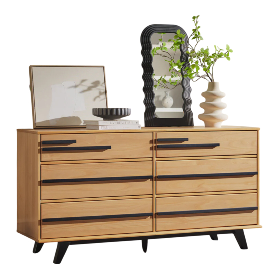
Summary of Contents for Walker Edison BR6DREBDR
- Page 1 Item # : BR6DREBDR Assembly Instructions V1 Revised 07/2022 2018...
- Page 2 and hammmer...
-
Page 3: Parts List
Parts List Part# Description Part# Description Top panel Right drawer side Right side panel Drawer bottom Left side panel Drawer back Bottom panel Small drawer front Crossbeam foot Small drawer handle Left foot Drawer handle Back panel Large drawer handle Right foot Leg crossbeam foot Drawer runner... -
Page 4: Hardware List
Hardware List Ø8*30mm Wood dowel Ø8*20mm Wood dowel Screw Ø3,5*25mm Ø3,5*30mm Screw Ø4,0*40mm Screw Ø10*10 Nail Ø7*60mm Screw Hex Key Glue 1486mm “H” Profile Wall anchor Washer Ø6mm Screw Ø4,5*25mm Tape measure and hammer recommended for assembly (not included) - Page 5 Step 1 Please assemble on a clean soft surface to avoid damage. Ø8*30mm Insert wood dowel (A) and glue (I) Ø8*20mm into parts (2, 3, 5, 12, 13, 16, 17, 19, 20, 21). Insert wood dowel (B) and glue (I) into part (9).
- Page 6 Step 2 Attach part (20) to parts (3,21)using screw (D) Ø3,5*30mm Step 3 Attach part (20) to parts (21,2)using screw (D) Ø3,5*30mm...
- Page 7 Step 4 Attach part (4) to boby with screws (E) Ø4,0*40mm Step 5 Use screw (D) to attach part (5) to part (6,8) Ø3,5*30mm...
- Page 8 Step 6 Ø4,0*40mm Use screw (E) to attach legs to body with screws (E) Ø7*60mm and use screw (G) and hex key (H) to attach the feet to the body. Step 7 Ø3,5*30mm Attach cross beam (19) to body using screw (D, E) Ø4,0*40mm...
- Page 9 Step 8 Use screw (D) to attach part (1) to body Ø3,5*30mm Step 9 Ø10*10 Secure back panel (7) with part (J) to body with nails (F) 1486mm...
- Page 10 Step 10 FRONT Use screw (C) attach parts (9) to BOTH sides of part (2,3,21) NOTE: The extra holes in part (9) should face the top of Ø3,5*25mm part (21) Step 11 FRONT Insert wood dowel (A) into the front hole in the drawer rails (9) Ø8*30mm P.10...
- Page 11 Step 12 Attach parts (11,12) to part (15) , insert panel (13) into groves and secure part (14) with screws(D). Attach parts (16,17) to part (15) , with screws(N), using the predrilled holes. The side drawer with WARNING Ø3,5*30mm LABEL, should be mouted in highest drawer.
- Page 12 Step 13 Attach parts (11,12) to part (10) , insert panel (13) into groves and secure part (14) with screws(D). Attach parts (18) to part (10) , with screws(N) using predrilled holes. Ø3,5*30mm Ø4,5*25mm P.12...
- Page 13 Step 14 Insert wood dowel (A) on the inside of all drawers while drawers is inside the unit. Make sure dowel is flush Ø8*30mm with panel. Assembly Complete! Maximum 24 LBS per drawer. P.13...
- Page 14 Wall anchor and hardware are included with this product. Please make sure hardware is suitable for your walls before types of anchors. 1 st Attach part (K) Back panel in the frame of superior panel unit. Insert part (M) in the hole. 2 nd Wall Ø6mm...
Need help?
Do you have a question about the BR6DREBDR and is the answer not in the manual?
Questions and answers