Advertisement
Quick Links
Advertisement

Related Manuals for Walker Edison BR6DLYDDR


Summary of Contents for Walker Edison BR6DLYDDR
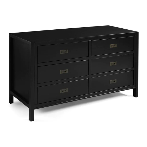
- Page 1 Item # : BR6DLYDDR Assembly Instructions Please visit our website for the most current instructions, assembly tips, to report damage or request parts. www.walkeredson.com Revised 10/2019 Copyright © 2018, by Walker Edson Furniture Co., LLC, All rights reserved.
-
Page 3: Parts List
Parts List This drawer side needs to be assembled in the highest drawer WARNING Serious or fatal crushing injuries can occur from furniture tip-over. To help prevent tip-over: ·Install tipover restraint provided. ·Place heaviest items in the lowest drawers. ·Do not set Tv’s or other heavy objects on top of this product,unless the product is specifically designed to accommodate them. -
Page 4: Hardware List
Hardware List 8,0 x 30mm 4,0 x 40mm Screw 4,0 x 30mm Screw 14 x 14mm Cam Lock 3,0 x 12mm Screw 96 x 40mm Puller 8,0 x 40mm 10 x 10mm 5,5 x 28mm Screw Ribbon Washer 3,5 x 14mm Screw Philips head screwdriver required for assembly (not included) - Page 5 Step 1 Insert wood dowel A (x66) into parts (1),(4),(5),(6),(7),(9),(12),(13), (15),(16). (6x) (2x) (2x) (4x) (4x) Step 2 Insert Cam Lock I (x6) into parts (2),(3).
- Page 6 Step 3 Insert screw B (x8) C (12) into parts (2),(3),(9),(6),(8). Step 4 Insert screw C (x3) into parts (9).
- Page 7 Step 5 Insert screw B (x2) C (x3) into parts (4),(1). Step 6 Insert screw B (x3) Cam lock D (x3) into parts (2),(1).
- Page 8 Step 7 Insert screw B (x4), C (x2) into parts (5),(7). Step 8 Insert screw B (x3), C (X2) Cam lock D (x3) into parts (3).
- Page 9 Step 9 Insert screw B (x4) into parts (6). 3,5 x 14mm Attach part (J) with Screw (L) and Washer (K) inside of superior panel unit. Step 10 Let the Ribbon (J) to outside and Insert Nail H (x40) into parts (17).
- Page 10 Step 11 Insert screw C (x16) into parts (12),(13),(14). (2x) Step 12 Insert screw C (x32) into parts (15),(16),(14). (4x) P.10...
- Page 11 Step 13 Wall anchor and hardware are included with this product. Please make sure hardware is suitable for your walls before types of anchors. Insert part (M) in the hole. Wall Ø6mm CHECK FOR HIDDEN PIPES AND CABLES BEFORE DRILLING P.11...
-
Page 12: Final Assembly
Step 15 Use screw E (x12) to attach Puller F (x6) to the drawers. (12x) (6x) Final Assembly...
Need help?
Do you have a question about the BR6DLYDDR and is the answer not in the manual?
Questions and answers